EP0596664A1 - Linsenanordnung und Engkontakt-Bildsensor mit solcher - Google Patents
Linsenanordnung und Engkontakt-Bildsensor mit solcher Download PDFInfo
- Publication number
- EP0596664A1 EP0596664A1 EP93308640A EP93308640A EP0596664A1 EP 0596664 A1 EP0596664 A1 EP 0596664A1 EP 93308640 A EP93308640 A EP 93308640A EP 93308640 A EP93308640 A EP 93308640A EP 0596664 A1 EP0596664 A1 EP 0596664A1
- Authority
- EP
- European Patent Office
- Prior art keywords
- lens
- overlap
- array
- lens elements
- image sensor
- Prior art date
- Legal status (The legal status is an assumption and is not a legal conclusion. Google has not performed a legal analysis and makes no representation as to the accuracy of the status listed.)
- Granted
Links
Images


Classifications
-
- G—PHYSICS
- G02—OPTICS
- G02B—OPTICAL ELEMENTS, SYSTEMS OR APPARATUS
- G02B3/00—Simple or compound lenses
- G02B3/0006—Arrays
- G02B3/0037—Arrays characterized by the distribution or form of lenses
- G02B3/005—Arrays characterized by the distribution or form of lenses arranged along a single direction only, e.g. lenticular sheets
-
- G—PHYSICS
- G02—OPTICS
- G02B—OPTICAL ELEMENTS, SYSTEMS OR APPARATUS
- G02B3/00—Simple or compound lenses
- G02B3/0087—Simple or compound lenses with index gradient
-
- H—ELECTRICITY
- H04—ELECTRIC COMMUNICATION TECHNIQUE
- H04N—PICTORIAL COMMUNICATION, e.g. TELEVISION
- H04N1/00—Scanning, transmission or reproduction of documents or the like, e.g. facsimile transmission; Details thereof
- H04N1/024—Details of scanning heads ; Means for illuminating the original
- H04N1/028—Details of scanning heads ; Means for illuminating the original for picture information pick-up
- H04N1/03—Details of scanning heads ; Means for illuminating the original for picture information pick-up with photodetectors arranged in a substantially linear array
- H04N1/031—Details of scanning heads ; Means for illuminating the original for picture information pick-up with photodetectors arranged in a substantially linear array the photodetectors having a one-to-one and optically positive correspondence with the scanned picture elements, e.g. linear contact sensors
- H04N1/0311—Details of scanning heads ; Means for illuminating the original for picture information pick-up with photodetectors arranged in a substantially linear array the photodetectors having a one-to-one and optically positive correspondence with the scanned picture elements, e.g. linear contact sensors using an array of elements to project the scanned image elements onto the photodetectors
- H04N1/0312—Details of scanning heads ; Means for illuminating the original for picture information pick-up with photodetectors arranged in a substantially linear array the photodetectors having a one-to-one and optically positive correspondence with the scanned picture elements, e.g. linear contact sensors using an array of elements to project the scanned image elements onto the photodetectors using an array of optical fibres or rod-lenses
-
- H—ELECTRICITY
- H04—ELECTRIC COMMUNICATION TECHNIQUE
- H04N—PICTORIAL COMMUNICATION, e.g. TELEVISION
- H04N1/00—Scanning, transmission or reproduction of documents or the like, e.g. facsimile transmission; Details thereof
- H04N1/024—Details of scanning heads ; Means for illuminating the original
- H04N1/028—Details of scanning heads ; Means for illuminating the original for picture information pick-up
- H04N1/03—Details of scanning heads ; Means for illuminating the original for picture information pick-up with photodetectors arranged in a substantially linear array
- H04N1/031—Details of scanning heads ; Means for illuminating the original for picture information pick-up with photodetectors arranged in a substantially linear array the photodetectors having a one-to-one and optically positive correspondence with the scanned picture elements, e.g. linear contact sensors
- H04N1/0315—Details of scanning heads ; Means for illuminating the original for picture information pick-up with photodetectors arranged in a substantially linear array the photodetectors having a one-to-one and optically positive correspondence with the scanned picture elements, e.g. linear contact sensors using photodetectors and illumination means mounted on separate supports or substrates or mounted in different planes
-
- H—ELECTRICITY
- H04—ELECTRIC COMMUNICATION TECHNIQUE
- H04N—PICTORIAL COMMUNICATION, e.g. TELEVISION
- H04N1/00—Scanning, transmission or reproduction of documents or the like, e.g. facsimile transmission; Details thereof
- H04N1/024—Details of scanning heads ; Means for illuminating the original
- H04N1/028—Details of scanning heads ; Means for illuminating the original for picture information pick-up
- H04N1/03—Details of scanning heads ; Means for illuminating the original for picture information pick-up with photodetectors arranged in a substantially linear array
- H04N1/031—Details of scanning heads ; Means for illuminating the original for picture information pick-up with photodetectors arranged in a substantially linear array the photodetectors having a one-to-one and optically positive correspondence with the scanned picture elements, e.g. linear contact sensors
- H04N1/0318—Integral pick-up heads, i.e. self-contained heads whose basic elements are a light-source, a lens array and a photodetector array which are supported by a single-piece frame
-
- H—ELECTRICITY
- H04—ELECTRIC COMMUNICATION TECHNIQUE
- H04N—PICTORIAL COMMUNICATION, e.g. TELEVISION
- H04N2201/00—Indexing scheme relating to scanning, transmission or reproduction of documents or the like, and to details thereof
- H04N2201/024—Indexing scheme relating to scanning, transmission or reproduction of documents or the like, and to details thereof deleted
- H04N2201/028—Indexing scheme relating to scanning, transmission or reproduction of documents or the like, and to details thereof deleted for picture information pick-up
- H04N2201/03—Indexing scheme relating to scanning, transmission or reproduction of documents or the like, and to details thereof deleted for picture information pick-up deleted
- H04N2201/031—Indexing scheme relating to scanning, transmission or reproduction of documents or the like, and to details thereof deleted for picture information pick-up deleted deleted
- H04N2201/03104—Integral pick-up heads, i.e. self-contained heads whose basic elements are a light source, a lens and a photodetector supported by a single-piece frame
- H04N2201/03108—Components of integral heads
- H04N2201/03112—Light source
-
- H—ELECTRICITY
- H04—ELECTRIC COMMUNICATION TECHNIQUE
- H04N—PICTORIAL COMMUNICATION, e.g. TELEVISION
- H04N2201/00—Indexing scheme relating to scanning, transmission or reproduction of documents or the like, and to details thereof
- H04N2201/024—Indexing scheme relating to scanning, transmission or reproduction of documents or the like, and to details thereof deleted
- H04N2201/028—Indexing scheme relating to scanning, transmission or reproduction of documents or the like, and to details thereof deleted for picture information pick-up
- H04N2201/03—Indexing scheme relating to scanning, transmission or reproduction of documents or the like, and to details thereof deleted for picture information pick-up deleted
- H04N2201/031—Indexing scheme relating to scanning, transmission or reproduction of documents or the like, and to details thereof deleted for picture information pick-up deleted deleted
- H04N2201/03104—Integral pick-up heads, i.e. self-contained heads whose basic elements are a light source, a lens and a photodetector supported by a single-piece frame
- H04N2201/03108—Components of integral heads
- H04N2201/03129—Transparent cover or transparent document support mounted on the head
-
- H—ELECTRICITY
- H04—ELECTRIC COMMUNICATION TECHNIQUE
- H04N—PICTORIAL COMMUNICATION, e.g. TELEVISION
- H04N2201/00—Indexing scheme relating to scanning, transmission or reproduction of documents or the like, and to details thereof
- H04N2201/024—Indexing scheme relating to scanning, transmission or reproduction of documents or the like, and to details thereof deleted
- H04N2201/028—Indexing scheme relating to scanning, transmission or reproduction of documents or the like, and to details thereof deleted for picture information pick-up
- H04N2201/03—Indexing scheme relating to scanning, transmission or reproduction of documents or the like, and to details thereof deleted for picture information pick-up deleted
- H04N2201/031—Indexing scheme relating to scanning, transmission or reproduction of documents or the like, and to details thereof deleted for picture information pick-up deleted deleted
- H04N2201/03104—Integral pick-up heads, i.e. self-contained heads whose basic elements are a light source, a lens and a photodetector supported by a single-piece frame
- H04N2201/03108—Components of integral heads
- H04N2201/03141—Photodetector lens
-
- H—ELECTRICITY
- H04—ELECTRIC COMMUNICATION TECHNIQUE
- H04N—PICTORIAL COMMUNICATION, e.g. TELEVISION
- H04N2201/00—Indexing scheme relating to scanning, transmission or reproduction of documents or the like, and to details thereof
- H04N2201/024—Indexing scheme relating to scanning, transmission or reproduction of documents or the like, and to details thereof deleted
- H04N2201/028—Indexing scheme relating to scanning, transmission or reproduction of documents or the like, and to details thereof deleted for picture information pick-up
- H04N2201/03—Indexing scheme relating to scanning, transmission or reproduction of documents or the like, and to details thereof deleted for picture information pick-up deleted
- H04N2201/031—Indexing scheme relating to scanning, transmission or reproduction of documents or the like, and to details thereof deleted for picture information pick-up deleted deleted
- H04N2201/03104—Integral pick-up heads, i.e. self-contained heads whose basic elements are a light source, a lens and a photodetector supported by a single-piece frame
- H04N2201/03108—Components of integral heads
- H04N2201/03145—Photodetector
-
- H—ELECTRICITY
- H04—ELECTRIC COMMUNICATION TECHNIQUE
- H04N—PICTORIAL COMMUNICATION, e.g. TELEVISION
- H04N2201/00—Indexing scheme relating to scanning, transmission or reproduction of documents or the like, and to details thereof
- H04N2201/024—Indexing scheme relating to scanning, transmission or reproduction of documents or the like, and to details thereof deleted
- H04N2201/028—Indexing scheme relating to scanning, transmission or reproduction of documents or the like, and to details thereof deleted for picture information pick-up
- H04N2201/03—Indexing scheme relating to scanning, transmission or reproduction of documents or the like, and to details thereof deleted for picture information pick-up deleted
- H04N2201/031—Indexing scheme relating to scanning, transmission or reproduction of documents or the like, and to details thereof deleted for picture information pick-up deleted deleted
- H04N2201/03104—Integral pick-up heads, i.e. self-contained heads whose basic elements are a light source, a lens and a photodetector supported by a single-piece frame
- H04N2201/0315—Details of integral heads not otherwise provided for
- H04N2201/03166—Additional light shielding member
Definitions
- This invention relates to a lens array and a close contact type image sensor using the same.
- the lens array of the present invention is particularly suitable for use in a close contact type image sensor adapted to be in close contact with an original and effect reading.
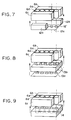
- FIG. 14 of the accompanying drawings is a cross-sectional view showing the structure of a close contact type image sensor according to the prior art.
- a sensor unit is comprised of a sensor module (constituting a sensor array) 4 comprising a sensor IC 1 having a plurality of pixels for effecting photoelectric conversion arranged, protective film 2 and a substrate 3 having these mounted thereon, an LED array 5 which is a light source for illuminating an original, a lens element body (constituting a lens array) 6 for forming the image of the original on the light receiving portion of the sensor, a transparent member 7 in close contact with the original 9 to support it, and a frame 8 supporting these members.
- the original 9 is illuminated by the light source (LED array 5), diffused reflected light on the read line of the original is imaged on the pixel array of the sensor by the lens element body 6, the light and shade information of the original had by the reflected light, i.e., the intensity of the light, is converted into an electrical signal by the individual sensor pixels and is delivered in the main scanning direction.
- the relative position of the original and the sensor pixel array is then moved in the sub-scanning direction and the data delivery in the main scanning direction is repeated to thereby convert two-dimensional image information into a time-serial electrical signal.
- lens element body use can be made, for example, of one comprising a plurality of lens elements each having a refractive index distribution in a direction orthogonal to the optical axis. More specifically, use can be made of one comprising a number of optical fibers each having a refractive index distribution in a direction orthogonal to the optical axis and arranged on a straight line, and since the individual optical fibers exhibit a lens action, the lens element body as a whole acts as a small and long imaging lens.
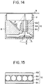
- Figure 15 of the accompanying drawings shows the opening portions of the lens element body, and is a view of the lens element body 6 as it is seen from the sensor module 4 side.
- the reference character 6a designates the opening portions of the lens element body
- the reference characters 6b and 6c denote support plates
- the reference character 6d designates a member of resin or the like holding the lens elements.
- FIG. 16A a grated index type optical fiber lens array as shown in Figures 16A and 16B of the accompanying drawings taken as an example of the lens element body.
- individual lens elements image erectly at one to one magnification an area of diameter Xo on the surface of an original on the surface of the sensor.
- a number of such lens elements are arranged on a straight line as shown in Figure 16B, whereby the images of the individual lens elements are overlapped to thereby form a long image surface.
- the depth of field when an image is formed by the combination of the images of a plurality of lens elements is considered as follows.
- the depth of field can be improved by making the angle of opening ⁇ of each individual lens element small, but in this case, the optical path length TC (P-q) becomes great, and when such lens element body is used in a close contact type image sensor as in the example of the prior art, the body becomes bulky. Also, the quantity of light reaching the image surface decreases remarkably and the burden applied to the light source becomes great. Further, such a lens element body having a great depth of field is expensive.
- An embodiment of the present invention provides a lens array and/or a close contact type image sensor having a great combined depth of field.
- a lens array according to an embodiment of the present invention is provided with a lens element body comprising a plurality of lens elements arranged, and an overlap limiting member provided between the lens elements of said lens element body for limiting the overlap of images.
- a close contact type image sensor is a close contact type image sensor provided with a transparent member for supporting an original, a light source for illuminating said original, an optical element array for directing reflected light from said original, and a sensor array for photoelectrically converting the directed image of the original, characterized in that the lens array of the above-described embodiment is used as said optical element array.
- a close contact type image sensor is characterized in that in the close contact type image sensor of the above-described first embodiment, an overlap limiting member having a plurality of opening portions corresponding to the respective lens elements is installed between the lens element body and the sensor array so that the optical axis of each lens element and the center of each of said opening portions may coincide with each other.
- a close contact type image sensor is characterized in that in the close contact type image sensor of the above-described first embodiment, said overlap limiting member has a plurality of light transmitting members corresponding to the lens elements, and the space between adjacent ones of said light transmitting members is shielded from light.
- the lens array is preferably such that in a lens element body comprising a plurality of lens elements arranged, there is provided an overlap limiting member for limiting the overlap of the images between the lens elements, to thereby decrease the number of lens elements concerned in imaging without increasing the optical path length, that is, for example, make the overlap degree m in Figure 18 small and improve the combined depth of field as the lens element body.
- the quantity of transmitted light decreases in accordance with a decrease in the number of lens elements concerned in imaging, but the rate of decrease is small as compared with a case where the angle of opening of each individual lens element is made small.
- the close contact type image sensor of the first embodiment of the present invention uses the above-described lens array of the present invention as an imaging optical system, whereby it becomes a compact and low-cost sensor having a great depth of field.
- the close contact type image sensor of the second embodiment of the present invention is such that in the close contact type image sensor of the above-described first embodiment of the present invention, an overlap limiting member having a plurality of opening portions corresponding to the respective lens elements is installed between the lens element body and the sensor array so that the optical axis of each lens element and the center of each of said opening portions may coincide with each other, to thereby suitably set the position of each of the opening portions of the overlap limiting member (the position between the lens element body and the sensor array) and the diameter of each opening portion, thereby controlling the overlap of images so as to become small and improving the depth of field.
- the close contact type image sensor of the third embodiment of the present invention is such that in the close contact type image sensor of the above-described first embodiment of the present invention, said overlap limiting member has a plurality of light transmitting members corresponding to the lens elements and the space between adjacent one of said light transmitting members is shielded from light to thereby control the overlap of images between the lens elements so as to become small and improve the depth of field, as in the close contact type image sensor of the above-described second embodiment of the present invention.
- Figure 1 is a cross-sectional view of a first embodiment of the close contact type image sensor of the present invention.
- Figures 2A and 2B are an enlarged view and a functional illustration, respectively, of an overlap limiting member in Figure 1.
- Figure 3 shows the external appearance of the overlap limiting member.
- Figure 4 shows the external appearance of an overlap limiting member of another construction.
- Figure 5 is a cross-sectional view of a second embodiment of the close contact type image sensor of the present invention.
- Figures 6A and 6B are an enlarged view and a functional illustration, respectively, of an overlap limiting member in Figure 5.
- Figure 7 is a pictorial perspective view of the overlap limiting member.
- Figure 8 is a pictorial perspective view of an overlap limiting member of another construction.
- Figure 9 is a pictorial perspective view of an overlap limiting member of still another construction.
- Figure 10 is a cross-sectional view of a third embodiment of the close contact type image sensor of the present invention.
- Figures 11A and 11B are an enlarged view and a functional illustration, respectively, of an overlap limiting member in Figure 10.
- Figure 12 is a pictorial perspective view of the overlap limiting member.
- Figure 13 is a pictorial perspective view of an overlap limiting member of another construction.
- Figure 14 is a cross-sectional view showing the structure of the close contact type image sensor of the present invention.
- Figure 15 shows the external appearance of a lens element array (grated index type optical fiber lens array).
- FIGS 16A and 16B are functional illustrations of the lens element body (grated index type optical fiber lens array).
- Figures 17A and 17B illustrate the depths of field of a lens element and a lens element body.
- Figure 18 is a graph showing the relation between the overlap degree m and the depth of field of the lens element body.
- Figure 19 shows an example of the use of a sensor having a great depth of field.
- Figure 1 is a cross-sectional view of a first embodiment of the close contact type image sensor of the present invention.
- Figure 2A is a sub-scanning cross-sectional view of the portion of the first embodiment of the present invention in which an overlap limiting member is provided, and
- Figure 2B is a main scanning cross-sectional view of the same portion.
- the same constituent members as the constituent members of Figure 14 are given the same reference characters and need not be described.
- an overlap limiting member 10 is provided in the sensor side opening portion of a lens element body 6 comprising a plurality of erect one-to-one magnification imaging type lens elements arranged (in the present embodiment, the lens element body 6 and the overlap limiting member 10 together constitute a lens array) to limit the overlap of images between the lens elements and make the imaging diameter small to thereby make the combined angle of opening as the lens array small and improve the combined depth of field.
- Figure 3 shows the external appearance of the overlap limiting member.
- the overlap limiting member is of a shape in which light transmitting windows 10' of a diameter ⁇ are formed in a film-like opaque member at a pitch equal to a lens pitch D, and the image diameter X is controlled by the size of the window diameter ⁇ .
- the overlap limiting member may be sticked on the lens element body or directly printed on the lens, or may be provided on a frame 8 side.
- the coefficient of thermal expansion of the frame 8 need be adjusted to that of the lens element body 6 so that the relative position of the lens element body 6 and the frame 8 may not be varied by temperature.
- the shape of the frame may be any shape effective to limit the overlap of images between the lens elements.
- the shape of the overlap limiting member may be any shape effective to limit the overlap of images between the lens elements.
- Figure 4 shows another shape of the overlap limiting member. In this case, the effect of an improvement in the depth of field is obtained only in the main scanning direction.
- Figure 5 is a cross-sectional view of a second embodiment of the close contact type image sensor of the present invention.
- the reference character 12a designates an overlap limiting member
- the reference character 12b denotes a spacer for prescribing the position thereof.
- the lens element body 6, the overlap limiting member 12a and the spacer 12b together constitutes a lens array.
- the overlap limiting member is provided with a predetermined distance t relative to the lens element body with the spacer interposed therebetween.
- the other members are the same as the constituent members of Figure 1 and therefore are given the same reference characters and need not be described.
- Figure 7 is a pictorial perspective view of the overlap limiting member.
- the limitation of the overlap of images is effected by the diameter ⁇ of windows 12' and the thickness t of the spacer, as shown in Figures 6A and 6B. If the overlap of images is limited by the diameter ⁇ of the windows, the combined angle of opening of the lens element body will become small and the quantity of light transmitted to the image surface will decrease and therefore, the limitation by the thickness t of the spacer is more effective, but in this case, if the thickness t of the spacer is made too great, the images of the adjacent lens elements will leak in and the effect of an improvement in the depth of field will be lost.
- a spacer 13b is made into a grating-like configuration, the leaking light will be intercepted, whereby the effect of an improvement in the depth of field will become great.
- the construction of Figure 9 in which the spacer and the overlap limiting member are made integral with each other is possible.
- the overlap limiting member may be directly made in the sensor frame.
- the coefficient of thermal expansion of the overlap limiting member need be adjusted to that of the lens element body so that the position thereof relative to the lens element body may not be varied by temperature.
- the shape of the windows of the overlap limiting member may be any shape effective to limit the overlap of images.
- Figure 10 is a cross-sectional view of a third embodiment of the close contact type image sensor of the present invention.
- Figure 12 is a perspective view showing the construction of a lens array.
- the reference numeral 15 designates an overlap limiting member.
- the same constituent members as those in Figure 14 are given the same reference characters and need not be described.
- the overlap limiting member 15 is of the same diameter as the lens element body 6 (grated index type optical fiber array comprising a number of optical fibers each having a refractive index distribution in a direction orthogonal to the optical axis and arranged on a straight line), and is comprised of outer frames 15b, 15c and a light transmitting member 15a having its outer peripheral portion shielded from light, and the light transmitting member is manufactured with the step of endowing it with a refractive index distribution omitted in the manufacturing process of an optical fiber lens array.
- the reference character 6a denotes lens elements, and the reference characters 6b and 6c designate outer frames.
- Such an overlap limiting member 15 is equal in its outside dimensions inclusive of the light transmitting member to the lens element body, and can be mounted on each lens element at 1 : 1 without any pitch deviation. Also, the materials of the members are the same and therefore, no pitch deviation is caused for any variation in temperature. Also, manufacture may be made with the light transmitting member 15a made coincident with the outer frames 6b, 6c of the lens element body.
- the overlap limiting member 15 has its thickness t varied as shown in Figures 11A and 11B to thereby control the radius X of images and also limit the overlap of images. Also, since the diameter of the light transmitting windows of the overlap limiting member is equal to the diameter of the lens elements, the decrease in the quantity of light transmitted to the image surface is small.
- FIG 13 is a perspective view showing another construction of the overlap limiting member.
- this overlap limiting member comprises a number of blocks of light transmitting members having a shorter side a equal to the diameter D of the lens elements and coupled together in a straight line form by a light intercepting adhesive agent, and the shorter side a is made coincident with the diameter D of the lens elements and the blocks are installed in the opening portions of the lens element body, whereby the overlap of images between the lens elements is controlled.
- an overlap limiting member is provided between lens elements, whereby the combined angle of opening as the lens array can be made small and the combined depth of field can be improved. Accordingly, the image sensor becomes difficult to be affected by the unevenness or floating of an original and the application thereof to a flat bed scanner or the like becomes possible, and the range of use of the sensor can be widened.
- the senor can be made lower in cost and more compact than when use is made of an expensive lens array having a great optical path length, and conventional parts can be employed and this leads to the standardization of parts which in turn leads to the possibility of reducing the manufacturing cost.
- an overlap limiting member having a plurality of opening portions corresponding to lens elements is installed between a lens element body and a sensor array so that the optical axis of the lens elements may coincide with the center of each of said opening portions, whereby the overlap of images between the lens elements can be limited and thus, as compared with a case where use is made of a lens array of the conventional long focus type, there can be realized a close contact type image sensor which is compact and low in cost as well as great in depth of field.
- the overlap limiting member has a plurality of light transmitting members corresponding to lens elements and the space between adjacent ones of the light transmitting members is shielded from light, whereby the overlap of images between the lens elements can be limited and thus, as compared with a case where use is made of a lens array of the conventional long focus type, there can be realized a close contact type image sensor which is compact and low in cost as well as great in depth of field.
Applications Claiming Priority (6)
| Application Number | Priority Date | Filing Date | Title |
|---|---|---|---|
| JP31801692 | 1992-11-04 | ||
| JP318016/92 | 1992-11-04 | ||
| JP105985/93 | 1993-04-09 | ||
| JP10598593 | 1993-04-09 | ||
| JP280718/93 | 1993-10-15 | ||
| JP5280718A JP2815130B2 (ja) | 1992-11-04 | 1993-10-15 | レンズアレイ及びそれを用いた密着型イメージセンサー |
Publications (2)
| Publication Number | Publication Date |
|---|---|
| EP0596664A1 true EP0596664A1 (de) | 1994-05-11 |
| EP0596664B1 EP0596664B1 (de) | 1999-05-06 |
Family
ID=27310625
Family Applications (1)
| Application Number | Title | Priority Date | Filing Date |
|---|---|---|---|
| EP93308640A Expired - Lifetime EP0596664B1 (de) | 1992-11-04 | 1993-10-29 | Linsenanordnung und Engkontakt-Bildsensor mit solcher Anordnung |
Country Status (4)
| Country | Link |
|---|---|
| US (1) | US5661540A (de) |
| EP (1) | EP0596664B1 (de) |
| JP (1) | JP2815130B2 (de) |
| DE (1) | DE69324762T2 (de) |
Cited By (6)
| Publication number | Priority date | Publication date | Assignee | Title |
|---|---|---|---|---|
| EP0887993A2 (de) * | 1997-06-24 | 1998-12-30 | Canon Kabushiki Kaisha | Stablinsenanordnung und Bildlesevorrichtung und System, dass diese verwendet |
| EP0898181A2 (de) * | 1997-08-18 | 1999-02-24 | Nippon Sheet Glass Co., Ltd. | Stablinsengitter und Lebensgrossesbilderzeugungssystem das dieselben verwendet |
| EP0917341A1 (de) * | 1996-07-30 | 1999-05-19 | Rohm Co., Ltd. | Bildlese/aufzeichnungskopf und dafür benutzter integrierter schaltkreis |
| EP0926513A2 (de) * | 1997-12-24 | 1999-06-30 | Nippon Sheet Glass Co., Ltd. | Stablinsen-Matrix für optisches Abbildungssystem |
| WO2002007427A1 (fr) * | 2000-07-18 | 2002-01-24 | Matsushita Electric Industrial Co., Ltd. | Processeur d'images, son lecteur d'images et objectif a fibres, et procede de fabrication de l'objectif a fibres |
| US7860352B2 (en) | 2005-06-17 | 2010-12-28 | Panasonic Corporation | Light-collecting apparatus and contact-type solid-state imaging apparatus using the same |
Families Citing this family (20)
| Publication number | Priority date | Publication date | Assignee | Title |
|---|---|---|---|---|
| US6177980B1 (en) * | 1997-02-20 | 2001-01-23 | Kenneth C. Johnson | High-throughput, maskless lithography system |
| JP2003121608A (ja) * | 2001-10-10 | 2003-04-23 | Nippon Sheet Glass Co Ltd | 等倍結像用レンズアレイ、同アレイを用いた画像読取り装置および同装置を用いた携帯電子機器 |
| US8013289B2 (en) | 2006-11-15 | 2011-09-06 | Ether Precision, Inc. | Lens array block for image capturing unit and methods of fabrication |
| US20080158698A1 (en) * | 2006-12-29 | 2008-07-03 | Chao-Chi Chang | Lens barrel array and lens array and the method of making the same |
| US7813043B2 (en) | 2008-08-15 | 2010-10-12 | Ether Precision, Inc. | Lens assembly and method of manufacture |
| US8090250B2 (en) * | 2009-06-23 | 2012-01-03 | Ether Precision, Inc. | Imaging device with focus offset compensation |
| EP2287639A3 (de) * | 2009-08-17 | 2012-05-30 | Sony Corporation | Linsenanordnungsbildoptik für ein Linientastermodul |
| CN103297653A (zh) * | 2012-02-23 | 2013-09-11 | 菱光科技股份有限公司 | 接触式影像感测装置 |
| JP2013186195A (ja) * | 2012-03-06 | 2013-09-19 | Toshiba Tec Corp | 画像形成装置、レンズアレイ及びその形成方法 |
| US9823115B2 (en) * | 2012-07-12 | 2017-11-21 | Pixart Imaging Inc. | Packaged optical device having a specular reflection configuration |
| WO2017150512A1 (ja) | 2016-03-01 | 2017-09-08 | 三菱電機株式会社 | 画像読取装置 |
| JP2019101244A (ja) * | 2017-12-04 | 2019-06-24 | 富士通株式会社 | 光モジュール |
| US10707195B2 (en) * | 2018-10-09 | 2020-07-07 | Waymo Llc | Multichannel monostatic rangefinder |
| CN113614583B (zh) * | 2019-03-25 | 2023-02-17 | 三菱电机株式会社 | 图像读取装置 |
| JP7211316B2 (ja) * | 2019-09-26 | 2023-01-24 | 三菱電機株式会社 | 画像読取装置及びその製造方法 |
| US11956398B2 (en) | 2020-09-25 | 2024-04-09 | Mitsubishi Electric Corporation | Image reading device having an overlap preventer with slit plates |
| US20230412748A1 (en) * | 2021-01-29 | 2023-12-21 | Mitsubishi Electric Corporation | Image reading device |
| DE112022002969T5 (de) * | 2021-06-09 | 2024-04-11 | Mitsubishi Electric Corporation | Optisches Element und Bildlesevorrichtung |
| CN117413509A (zh) * | 2021-06-09 | 2024-01-16 | 三菱电机株式会社 | 光学部件以及图像读取装置 |
| JP7216240B1 (ja) * | 2022-07-04 | 2023-01-31 | 日本板硝子株式会社 | 光学装置及びイメージセンサ |
Citations (7)
| Publication number | Priority date | Publication date | Assignee | Title |
|---|---|---|---|---|
| EP0002736A1 (de) * | 1977-12-22 | 1979-07-11 | Agfa-Gevaert AG | Belichtungsanordnung für Kopiergeräte |
| JPS56161772A (en) * | 1980-05-15 | 1981-12-12 | Canon Inc | Original reader |
| JPS57188010A (en) * | 1981-05-15 | 1982-11-18 | Ricoh Co Ltd | Plate type lens array |
| JPS5849903A (ja) * | 1981-09-21 | 1983-03-24 | Canon Inc | マイクロレンズの遮光装置 |
| JPS6271373A (ja) * | 1985-09-24 | 1987-04-02 | Matsushita Electric Ind Co Ltd | 固体撮像装置 |
| EP0257798A2 (de) * | 1986-07-28 | 1988-03-02 | Xerox Corporation | Abbildungssystem mit einer oszillierenden Anordnung von Gradientenlinsen |
| EP0508709A2 (de) * | 1991-04-08 | 1992-10-14 | Canon Kabushiki Kaisha | Bildsensor des Kontakttyps |
Family Cites Families (7)
| Publication number | Priority date | Publication date | Assignee | Title |
|---|---|---|---|---|
| GB1275094A (en) * | 1968-08-22 | 1972-05-24 | Nippon Selfoc Co Ltd | Optical device for transmitting an image |
| US3909109A (en) * | 1971-08-09 | 1975-09-30 | Jenaer Glaswerk Schott & Gen | Optical fiber image magnifying apparatus |
| US4373780A (en) * | 1980-06-16 | 1983-02-15 | Xerox Corporation | Image transmitting system utilizing a gradient index lens |
| US4462662A (en) * | 1981-06-15 | 1984-07-31 | Xerox Corporation | Imaging system utilizing a gradient index lens array compensated for non-uniform object illumination |
| US4590492A (en) * | 1983-06-07 | 1986-05-20 | The United States Of America As Represented By The Secretary Of The Air Force | High resolution optical fiber print head |
| JPS6030259A (ja) * | 1983-07-29 | 1985-02-15 | Toshiba Corp | 画像情報読取り装置 |
| US4999648A (en) * | 1989-12-19 | 1991-03-12 | Eastman Kodak Company | Non-contact optical print head for image writing apparatus |
-
1993
- 1993-10-15 JP JP5280718A patent/JP2815130B2/ja not_active Expired - Fee Related
- 1993-10-29 EP EP93308640A patent/EP0596664B1/de not_active Expired - Lifetime
- 1993-10-29 DE DE69324762T patent/DE69324762T2/de not_active Expired - Fee Related
-
1996
- 1996-01-22 US US08/589,311 patent/US5661540A/en not_active Expired - Lifetime
Patent Citations (7)
| Publication number | Priority date | Publication date | Assignee | Title |
|---|---|---|---|---|
| EP0002736A1 (de) * | 1977-12-22 | 1979-07-11 | Agfa-Gevaert AG | Belichtungsanordnung für Kopiergeräte |
| JPS56161772A (en) * | 1980-05-15 | 1981-12-12 | Canon Inc | Original reader |
| JPS57188010A (en) * | 1981-05-15 | 1982-11-18 | Ricoh Co Ltd | Plate type lens array |
| JPS5849903A (ja) * | 1981-09-21 | 1983-03-24 | Canon Inc | マイクロレンズの遮光装置 |
| JPS6271373A (ja) * | 1985-09-24 | 1987-04-02 | Matsushita Electric Ind Co Ltd | 固体撮像装置 |
| EP0257798A2 (de) * | 1986-07-28 | 1988-03-02 | Xerox Corporation | Abbildungssystem mit einer oszillierenden Anordnung von Gradientenlinsen |
| EP0508709A2 (de) * | 1991-04-08 | 1992-10-14 | Canon Kabushiki Kaisha | Bildsensor des Kontakttyps |
Non-Patent Citations (4)
| Title |
|---|
| PATENT ABSTRACTS OF JAPAN vol. 11, no. 271 (E - 536) 3 September 1987 (1987-09-03) * |
| PATENT ABSTRACTS OF JAPAN vol. 6, no. 47 (E - 99) 26 March 1982 (1982-03-26) * |
| PATENT ABSTRACTS OF JAPAN vol. 7, no. 134 (P - 203) 11 June 1983 (1983-06-11) * |
| PATENT ABSTRACTS OF JAPAN vol. 7, no. 35 (P - 175) 10 February 1983 (1983-02-10) * |
Cited By (15)
| Publication number | Priority date | Publication date | Assignee | Title |
|---|---|---|---|---|
| US6222581B1 (en) | 1996-07-30 | 2001-04-24 | Rohm Co., Ltd. | Picture reading/writing head and integrated circuit used for the same |
| EP0917341A1 (de) * | 1996-07-30 | 1999-05-19 | Rohm Co., Ltd. | Bildlese/aufzeichnungskopf und dafür benutzter integrierter schaltkreis |
| EP0917341A4 (de) * | 1996-07-30 | 1999-07-14 | Rohm Co Ltd | Bildlese/aufzeichnungskopf und dafür benutzter integrierter schaltkreis |
| EP0887993A2 (de) * | 1997-06-24 | 1998-12-30 | Canon Kabushiki Kaisha | Stablinsenanordnung und Bildlesevorrichtung und System, dass diese verwendet |
| US6239421B1 (en) | 1997-06-24 | 2001-05-29 | Canon Kabushiki Kaisha | Rod lens array and image read apparatus and system using the same |
| EP0887993A3 (de) * | 1997-06-24 | 1999-10-13 | Canon Kabushiki Kaisha | Stablinsenanordnung und Bildlesevorrichtung und System, dass diese verwendet |
| EP0898181A2 (de) * | 1997-08-18 | 1999-02-24 | Nippon Sheet Glass Co., Ltd. | Stablinsengitter und Lebensgrossesbilderzeugungssystem das dieselben verwendet |
| EP0898181A3 (de) * | 1997-08-18 | 1999-09-22 | Nippon Sheet Glass Co., Ltd. | Stablinsengitter und Lebensgrossesbilderzeugungssystem das dieselben verwendet |
| EP0926513A2 (de) * | 1997-12-24 | 1999-06-30 | Nippon Sheet Glass Co., Ltd. | Stablinsen-Matrix für optisches Abbildungssystem |
| US6031668A (en) * | 1997-12-24 | 2000-02-29 | Nippon Sheet Glass Co., Ltd. | Optical imaging system |
| EP0926513A3 (de) * | 1997-12-24 | 1999-10-06 | Nippon Sheet Glass Co., Ltd. | Stablinsen-Matrix für optisches Abbildungssystem |
| WO2002007427A1 (fr) * | 2000-07-18 | 2002-01-24 | Matsushita Electric Industrial Co., Ltd. | Processeur d'images, son lecteur d'images et objectif a fibres, et procede de fabrication de l'objectif a fibres |
| US6933487B2 (en) | 2000-07-18 | 2005-08-23 | Matsushita Electric Industrial Co., Ltd. | Image reader and image processor having a light source forming trapezoid-shaped illuminance distribution in sub-scanning direction |
| US7512301B2 (en) | 2000-07-18 | 2009-03-31 | Panasonic Corporation | Image reader and image processor having a light source forming trapezoid-shaped illuminance distribution in sub-scanning direction |
| US7860352B2 (en) | 2005-06-17 | 2010-12-28 | Panasonic Corporation | Light-collecting apparatus and contact-type solid-state imaging apparatus using the same |
Also Published As
| Publication number | Publication date |
|---|---|
| JP2815130B2 (ja) | 1998-10-27 |
| US5661540A (en) | 1997-08-26 |
| JPH06342131A (ja) | 1994-12-13 |
| DE69324762T2 (de) | 1999-10-21 |
| DE69324762D1 (de) | 1999-06-10 |
| EP0596664B1 (de) | 1999-05-06 |
Similar Documents
| Publication | Publication Date | Title |
|---|---|---|
| EP0596664B1 (de) | Linsenanordnung und Engkontakt-Bildsensor mit solcher Anordnung | |
| US6545811B1 (en) | Lens unit for image formation, and image reader having lens unit | |
| JPH0762865B2 (ja) | 指紋画像入力装置 | |
| JPH07203125A (ja) | 画像読み取り装置 | |
| US4863251A (en) | Double gauss lens for a raster input scanner | |
| JP4077101B2 (ja) | レンズアレイ、およびこれを複数備えたレンズアレイ組立品 | |
| EP0898181A2 (de) | Stablinsengitter und Lebensgrossesbilderzeugungssystem das dieselben verwendet | |
| US5163117A (en) | Image transmitting element comprising an array of photo-transmissible holes | |
| US5256868A (en) | Contact scanners for scanning images of an illuminated film onto a photosensor array | |
| US5959783A (en) | Rod lens array and life-size imaging optical apparatus using the same | |
| JP4125910B2 (ja) | レンズアレイユニットおよびこれを備えた光学装置 | |
| US4771338A (en) | Image reading device for facsimile system | |
| EP1246450B1 (de) | Bildlesegerät | |
| JPS63984B2 (de) | ||
| JP3682817B2 (ja) | 画像読み取り装置の線状光源ユニット | |
| JP2839108B2 (ja) | イメージ読取ユニット | |
| JP3129809B2 (ja) | 原稿読取装置における原稿照明装置 | |
| JP4585056B2 (ja) | 密着イメージスキャナ | |
| EP1223739B1 (de) | Bildformungsgerät | |
| JP2003054025A (ja) | 画像伝達装置 | |
| JPH04326655A (ja) | 等倍読取装置 | |
| JPS63310262A (ja) | 画像読取装置 | |
| JP2000050010A (ja) | 光導波路型イメージセンサ | |
| JP3018560B2 (ja) | イメージセンサ | |
| JPH0793460A (ja) | データシンボル読み取り装置 |
Legal Events
| Date | Code | Title | Description |
|---|---|---|---|
| PUAI | Public reference made under article 153(3) epc to a published international application that has entered the european phase |
Free format text: ORIGINAL CODE: 0009012 |
|
| AK | Designated contracting states |
Kind code of ref document: A1 Designated state(s): DE FR GB IT NL |
|
| 17P | Request for examination filed |
Effective date: 19940923 |
|
| 17Q | First examination report despatched |
Effective date: 19960205 |
|
| GRAG | Despatch of communication of intention to grant |
Free format text: ORIGINAL CODE: EPIDOS AGRA |
|
| GRAG | Despatch of communication of intention to grant |
Free format text: ORIGINAL CODE: EPIDOS AGRA |
|
| GRAG | Despatch of communication of intention to grant |
Free format text: ORIGINAL CODE: EPIDOS AGRA |
|
| GRAH | Despatch of communication of intention to grant a patent |
Free format text: ORIGINAL CODE: EPIDOS IGRA |
|
| GRAH | Despatch of communication of intention to grant a patent |
Free format text: ORIGINAL CODE: EPIDOS IGRA |
|
| GRAA | (expected) grant |
Free format text: ORIGINAL CODE: 0009210 |
|
| AK | Designated contracting states |
Kind code of ref document: B1 Designated state(s): DE FR GB IT NL |
|
| PG25 | Lapsed in a contracting state [announced via postgrant information from national office to epo] |
Ref country code: NL Free format text: LAPSE BECAUSE OF FAILURE TO SUBMIT A TRANSLATION OF THE DESCRIPTION OR TO PAY THE FEE WITHIN THE PRESCRIBED TIME-LIMIT Effective date: 19990506 Ref country code: IT Free format text: LAPSE BECAUSE OF FAILURE TO SUBMIT A TRANSLATION OF THE DESCRIPTION OR TO PAY THE FEE WITHIN THE PRESCRIBED TIME-LIMIT;WARNING: LAPSES OF ITALIAN PATENTS WITH EFFECTIVE DATE BEFORE 2007 MAY HAVE OCCURRED AT ANY TIME BEFORE 2007. THE CORRECT EFFECTIVE DATE MAY BE DIFFERENT FROM THE ONE RECORDED. Effective date: 19990506 |
|
| REF | Corresponds to: |
Ref document number: 69324762 Country of ref document: DE Date of ref document: 19990610 |
|
| ET | Fr: translation filed | ||
| PLBE | No opposition filed within time limit |
Free format text: ORIGINAL CODE: 0009261 |
|
| STAA | Information on the status of an ep patent application or granted ep patent |
Free format text: STATUS: NO OPPOSITION FILED WITHIN TIME LIMIT |
|
| 26N | No opposition filed | ||
| REG | Reference to a national code |
Ref country code: GB Ref legal event code: IF02 |
|
| PGFP | Annual fee paid to national office [announced via postgrant information from national office to epo] |
Ref country code: DE Payment date: 20081031 Year of fee payment: 16 |
|
| PGFP | Annual fee paid to national office [announced via postgrant information from national office to epo] |
Ref country code: FR Payment date: 20081024 Year of fee payment: 16 |
|
| PGFP | Annual fee paid to national office [announced via postgrant information from national office to epo] |
Ref country code: GB Payment date: 20081029 Year of fee payment: 16 |
|
| REG | Reference to a national code |
Ref country code: FR Ref legal event code: ST Effective date: 20100630 |
|
| PG25 | Lapsed in a contracting state [announced via postgrant information from national office to epo] |
Ref country code: FR Free format text: LAPSE BECAUSE OF NON-PAYMENT OF DUE FEES Effective date: 20091102 Ref country code: DE Free format text: LAPSE BECAUSE OF NON-PAYMENT OF DUE FEES Effective date: 20100501 |
|
| PG25 | Lapsed in a contracting state [announced via postgrant information from national office to epo] |
Ref country code: GB Free format text: LAPSE BECAUSE OF NON-PAYMENT OF DUE FEES Effective date: 20091029 |