EP0596554A1 - Wellplatte für eingetauchten elektrischen Transformatorkessel, Verfahren zu ihrer Herstellung und Verwendung zur Montage eines Kessels - Google Patents
Wellplatte für eingetauchten elektrischen Transformatorkessel, Verfahren zu ihrer Herstellung und Verwendung zur Montage eines Kessels Download PDFInfo
- Publication number
- EP0596554A1 EP0596554A1 EP93202965A EP93202965A EP0596554A1 EP 0596554 A1 EP0596554 A1 EP 0596554A1 EP 93202965 A EP93202965 A EP 93202965A EP 93202965 A EP93202965 A EP 93202965A EP 0596554 A1 EP0596554 A1 EP 0596554A1
- Authority
- EP
- European Patent Office
- Prior art keywords
- panel
- tank
- waves
- wavy
- wave
- Prior art date
- Legal status (The legal status is an assumption and is not a legal conclusion. Google has not performed a legal analysis and makes no representation as to the accuracy of the status listed.)
- Granted
Links
Images


Classifications
-
- H—ELECTRICITY
- H01—ELECTRIC ELEMENTS
- H01F—MAGNETS; INDUCTANCES; TRANSFORMERS; SELECTION OF MATERIALS FOR THEIR MAGNETIC PROPERTIES
- H01F27/00—Details of transformers or inductances, in general
- H01F27/02—Casings
- H01F27/025—Constructional details relating to cooling
Definitions
- the present invention relates to the production of tanks of submerged electric transformers. More specifically, the invention relates to the manufacture of corrugated panels which must form the mother waves of tanks provided with cooling waves around their entire periphery.
- a tank of this type is obtained by assembling, by sealed welding of the edges of their front ends, four corrugated panels each forming one side of the tank. During the assembly of this one, the mother waves come to take place in the angles, at the rate of one by angle, in the prolongation of a side, so as to offer a support of fixing to the wavy end of the panel adjacent wavy forming this side.
- the waveguide constitutes the common assembled part of the ends of two consecutive wavy panels forming two adjacent sides at right angles to the tank, as shown in Figure 1 attached.
- the mother wave is therefore characterized by the fact that it forms, by one of these faces, the plane terminal part of a wavy panel, and that on its other opposite face it door, assembly fittings, "daughter" waves which are formed by the end part of the adjacent wavy panel extending beyond the limits of the internal perimeter of the tank.
- Swelling may occur while using the transformer in discontinuous operation. However, it can already appear when filling a new tank under the effect on the walls of the internal pressure of the coolant that the tank and the waves contain.
- the swellings can be very significant.
- the bellies which form on the face opposite to that constituted by the daughter waves, can distend until causing deformations which go beyond the elastic limit of the sheet steel of which the panels are made.
- the object of the present invention is to avoid untimely swelling of 1 wave-meter.
- the subject of the invention is a corrugated panel constituting a submerged electric transformer tank provided with waves around its entire periphery, a corrugated panel of which at least one terminal part is intended to constitute one face of a wave-meter. bearing on the other opposite face of daughter waves, characterized in that the face constituting said end portion comprises secondary waves constituted by folds forming stiffeners.
- the invention therefore consists in providing folds in the end part of a corrugated panel, usually flat, which after folding at said right angle of said end will constitute stiffeners which will prevent the mother wave from swelling.
- a marked advantage of the invention is that these stiffening plies can be oriented parallel to the waves, so that they can be produced as waves, at the same time as the waves, during the manufacture of the panel. Simply, they are less high, (for example 2cm) so as not to come up against the other waves when bending the end at right angles. As a general rule, two or even three folds are sufficient for most tanks. However, their number is certainly not limited by the invention, and it is possible to provide as many as desired or as needed, depending on the size of the tank to be achieve.
- the invention also relates to a method for producing a corrugated panel of a submerged electric transformer tank, at least one terminal part of which is intended to constitute one face of a waveguide, the other face, opposite , being provided with daughter waves provided by the wavy end part of an adjacent wavy panel, method characterized in that folds are made in said end part by repeating the drawing operation which serves to form the waves on the panel.
- a particularly advantageous aspect of the invention resides in the fact that the volume of the waves available for the coolant is thus increased.
- This increase is certainly modest, since it corresponds to the sum of the elementary volumes of each fold of rigidity practiced on the terminal part of the corrugated panel, but nevertheless sufficient to be able to eliminate the spacer cord which is conventionally disposed between the edges of the faces of the waveguide before tight welding of the latter.
- This spacer which is used to separate the opposite faces more than the conventional pinching at the edge, makes it possible to increase the interior volume of the waveguide.
- this spacer can be avoided, since its function is now ensured by the stiffness folds, which simplifies the assembly process of the tank.
- the invention thus also relates to an application of the wave panel with terminal part provided with folds of rigidity forming secondary waves to the production of a submerged electric transformer tank, which is characterized by the fact that the tight assembly with the part wavy end of the adjacent wavy panel is made by direct contact of the edges, without spacer.
- FIG. 1 shows a tank 1 in which takes place a transformer 2.
- the tank of generally rectangular parallelepiped shape, is essentially constituted by four adjacent wavy panels 3a, 3b, 3c and 3d, each forming one side of the tank. These panels, assembled at right angles by sealed welding of their ends, constitute the side wall 4 of the tank.
- a bottom 5 is attached to the base of this wall, and an upper flange 6, better visible in the following figures, ensures the sealed connection with a tank cover not shown.
- Each panel is provided with waves 8, mutually parallel, regularly spaced, oriented vertically extending over the height of the tank and visible prominently on the outside thereof.
- the corrugated panels 3a and 3c forming the short sides have an end portion 9 which comes in line with the other two sides of the tank and which serves as an assembly support for fixing the wavy ends 10 of the corrugated panels adjacent 3b and 3d.
- the waveguide 11 is formed from this terminal part 9 which, once the tank is mounted, becomes the only wave carrying daughter waves, which come from the wavy ends 10 of the adjacent panels 3b and 3d.
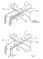
- FIGS. 2 and 3 showing a tank angle with more details.
- the wavy panels 3a and 3d provided with waves 8 and assembled at right angles in a sealed manner at their end by forming a wave-mother.
- the flange 6, which strengthens the mechanical strength of the assembly is formed by an angle iron, the upper flat iron of which is provided with orifices 7 for the passage of fastening means with the tank cover.
- a strip 13 the function of which will be explained below, forms a ribbon at the upper and lower edge of the corrugated panels, which is interposed between these and the angle iron 6 and the bottom of the tank respectively.
- Each corrugated panel such as 3a or 3d, is made up of a steel strip which carries the manufacturing of waves 8 formed by deep folds produced by stamping in a single pass.
- Each wave 8 thus has an internal volume which opens laterally in the enclosure of the tank. In this way a tank is produced, the side wall of which, formed by the apron of the wave panels, is provided with parallel slots extending over all the height and which put in direct communication the interior volume of the waves with the enclosure of the tank intended to receive the transformer.
- the tank After closing the waves at their upper and lower ends by pinching and sealing the edges, the tank can be filled with a coolant with dielectric properties, for example oil in which the transformer is bathed and which ensures the thermal maintenance of this at the desired level by evacuating the heat to the outside environment thanks to the large exchange surface offered by the radiator constituted by the corrugated panels.
- a coolant with dielectric properties for example oil in which the transformer is bathed and which ensures the thermal maintenance of this at the desired level by evacuating the heat to the outside environment thanks to the large exchange surface offered by the radiator constituted by the corrugated panels.
- the waveguide 11 is formed by assembling the flat end portion 9 of the wavy panel 3a with the wavy end 10 of the adjacent panel 3d.
- the end part 9 has been reinforced by folding the sheet back on itself. The assembly is carried out by welding the edges.
- a long wedge 12 has been interposed to further separate the faces of the waveguide than is possible only by pinching the edges. This increases the interior volume of the waveguide.
- This spacer 12 can be formed by a simple steel rod.
- the waveguide 11 is therefore formed during assembly of the tank and that its two opposite faces come, one from the planar end portion 9 of a panel (3a) and the other from the wavy end 10 of the adjacent panel (3d), the end of which the waves have the particularity of opening, not directly into the enclosure of the tank like the other waves, but into the interior volume of the waveguide, where their wave name "files".
- the terminal part of the corrugated panel is no longer planar but has secondary waves.
- These provisions are clearly visible in Figure 3, where we see that two stiffness plies 16 are raised on the end portion 9 'of the panel 3'a. forming the face of the mother wave 11 'turned opposite the waves 8 of this panel, constituting secondary waves therein.
- these stiffness folds are oriented vertically and extend over the height of the tank like the main waves 8. Their depth can however be significantly less than that of the waves 8.
- those - These conventionally have a depth ranging from 80 to 600 mm depending on the power of the transformer, while the depth of the stiffness folds can be limited to 15 or 20 mm.
- the face 9 ′ of the mother wave is no longer doubled in thickness by folding the sheet. Consequently, the sealed connection at the lateral edge can advantageously be produced, as shown in the figure, by a sliding assembly which facilitates the mounting of the tank thanks to the right-angled end flange 14 which engages in the corresponding slide 15 formed a this effect by rolling the sheet at the front end of the 3 'corrugated panel.
- FIG. 4 shows the panel 3 ′ a in the draft state during manufacture on a wave bender usually used for the production of wavy panels.
- stiffness folds can be freely oriented, it is understood that a choice of orientation parallel to the waves 8 has the advantage of being able to produce them with the existing punches, without modifications of the folder other than the different depth settings to provide for waves and stiffness folds.
- the folding of the terminal parts 9 ′ is done on a conventional press brake (flap folding machine) by rotation of 90 ° around the line 17 so as to find these end parts of the same side that the waves 8 relative to the apron 19. Then, by rotation in the opposite direction around the line 18, the front end is bent to form the rim 14 intended to take place, during assembly of the tank, in the slide 15 provided for this purpose at the end of the adjacent panel 3'd (fig. 3).
- the location of the fold lines 17 on the deck will generally be chosen so that the height of the terminal parts 9 ′ coincides with that of the waves 8.
- the invention extends to numerous variants, in particular for the production of stiffness waves 16, insofar as the characteristics of the claims below are respected.
Landscapes
- Engineering & Computer Science (AREA)
- Power Engineering (AREA)
- Housings And Mounting Of Transformers (AREA)
- Transformer Cooling (AREA)
- Laminated Bodies (AREA)
- Coils Of Transformers For General Uses (AREA)
Applications Claiming Priority (2)
| Application Number | Priority Date | Filing Date | Title |
|---|---|---|---|
| FR9213299A FR2697667B1 (fr) | 1992-11-03 | 1992-11-03 | Panneau ondé de cuve de transformateur électrique immergé, son procédé de réalisation, et son application au montage d'une cuve. |
| FR9213299 | 1992-11-03 |
Publications (2)
| Publication Number | Publication Date |
|---|---|
| EP0596554A1 true EP0596554A1 (de) | 1994-05-11 |
| EP0596554B1 EP0596554B1 (de) | 1997-09-10 |
Family
ID=9435242
Family Applications (1)
| Application Number | Title | Priority Date | Filing Date |
|---|---|---|---|
| EP93202965A Expired - Lifetime EP0596554B1 (de) | 1992-11-03 | 1993-10-22 | Wellplatte für Tauchtransformatortopf, Verfahren zu dessen Herstellung und Verwendung |
Country Status (5)
| Country | Link |
|---|---|
| EP (1) | EP0596554B1 (de) |
| AT (1) | ATE158101T1 (de) |
| DE (1) | DE69313779T2 (de) |
| ES (1) | ES2108210T3 (de) |
| FR (1) | FR2697667B1 (de) |
Cited By (2)
| Publication number | Priority date | Publication date | Assignee | Title |
|---|---|---|---|---|
| EP0671748A1 (de) * | 1994-03-10 | 1995-09-13 | France Transfo (S.A.) | Wärmetauscher für Gefäss eines eingetauchten elektrischen Transformator |
| FR2841880A1 (fr) * | 2002-07-08 | 2004-01-09 | Esac | Panneau alveolaire et cuve de transformateur immerge comprenant un tel panneau |
Families Citing this family (1)
| Publication number | Priority date | Publication date | Assignee | Title |
|---|---|---|---|---|
| FR2776822B1 (fr) * | 1998-03-25 | 2000-06-09 | France Transfo Sa | Ceinture ondee integrale pour cuve de transformateur electrique immerge |
Citations (5)
| Publication number | Priority date | Publication date | Assignee | Title |
|---|---|---|---|---|
| GB1256227A (en) * | 1968-04-03 | 1971-12-08 | Ass Eng Ltd | Improvements in or relating to heat exchangers |
| JPS55151313A (en) * | 1979-05-15 | 1980-11-25 | Toshiba Corp | Oil-filled electric apparatus tank |
| GB2068647A (en) * | 1980-01-30 | 1981-08-12 | Tokyo Shibaura Electric Co | Tanks for oil-cooled electrical induction apparatus |
| DE3627180A1 (de) * | 1986-08-11 | 1988-02-18 | Transformatoren Union Ag | Transformator mit fluessigkeitskuehlung |
| FR2629252A3 (fr) * | 1988-03-22 | 1989-09-29 | France Transfo Sa | Panneaux ondes, notamment pour transformateurs electriques ou analogues, leur procede et installation de fabrication |
-
1992
- 1992-11-03 FR FR9213299A patent/FR2697667B1/fr not_active Expired - Fee Related
-
1993
- 1993-10-22 EP EP93202965A patent/EP0596554B1/de not_active Expired - Lifetime
- 1993-10-22 AT AT93202965T patent/ATE158101T1/de not_active IP Right Cessation
- 1993-10-22 DE DE69313779T patent/DE69313779T2/de not_active Expired - Fee Related
- 1993-10-22 ES ES93202965T patent/ES2108210T3/es not_active Expired - Lifetime
Patent Citations (5)
| Publication number | Priority date | Publication date | Assignee | Title |
|---|---|---|---|---|
| GB1256227A (en) * | 1968-04-03 | 1971-12-08 | Ass Eng Ltd | Improvements in or relating to heat exchangers |
| JPS55151313A (en) * | 1979-05-15 | 1980-11-25 | Toshiba Corp | Oil-filled electric apparatus tank |
| GB2068647A (en) * | 1980-01-30 | 1981-08-12 | Tokyo Shibaura Electric Co | Tanks for oil-cooled electrical induction apparatus |
| DE3627180A1 (de) * | 1986-08-11 | 1988-02-18 | Transformatoren Union Ag | Transformator mit fluessigkeitskuehlung |
| FR2629252A3 (fr) * | 1988-03-22 | 1989-09-29 | France Transfo Sa | Panneaux ondes, notamment pour transformateurs electriques ou analogues, leur procede et installation de fabrication |
Non-Patent Citations (1)
| Title |
|---|
| PATENT ABSTRACTS OF JAPAN vol. 5, no. 23 (E - 45)<695> 12 February 1981 (1981-02-12) * |
Cited By (3)
| Publication number | Priority date | Publication date | Assignee | Title |
|---|---|---|---|---|
| EP0671748A1 (de) * | 1994-03-10 | 1995-09-13 | France Transfo (S.A.) | Wärmetauscher für Gefäss eines eingetauchten elektrischen Transformator |
| FR2717299A1 (fr) * | 1994-03-10 | 1995-09-15 | France Transfo Sa | Echangeur thermique de cuve de transformateur électrique immergé. |
| FR2841880A1 (fr) * | 2002-07-08 | 2004-01-09 | Esac | Panneau alveolaire et cuve de transformateur immerge comprenant un tel panneau |
Also Published As
| Publication number | Publication date |
|---|---|
| ATE158101T1 (de) | 1997-09-15 |
| EP0596554B1 (de) | 1997-09-10 |
| DE69313779T2 (de) | 1998-03-05 |
| FR2697667A1 (fr) | 1994-05-06 |
| ES2108210T3 (es) | 1997-12-16 |
| DE69313779D1 (de) | 1997-10-16 |
| FR2697667B1 (fr) | 1995-01-27 |
Similar Documents
| Publication | Publication Date | Title |
|---|---|---|
| EP2117963B1 (de) | Aus rechteckigen elementen zusammengesetze zylindrische struktur | |
| FR2554423A1 (fr) | Conteneur pour le transport de produits susceptibles de s'ecouler | |
| CH420974A (fr) | Emballage à extrémités ouvertes pour des boîtes | |
| EP0596554B1 (de) | Wellplatte für Tauchtransformatortopf, Verfahren zu dessen Herstellung und Verwendung | |
| EP2500115B1 (de) | Umformverfahren von mechanisch verschweißten Blechen starker Dicke, und durch dieses Verfahren erhaltene Struktur | |
| EP0567411B1 (de) | Seitenteil für die Montage eines Fahrzeugradiators | |
| FR2990714A1 (fr) | Boite de guidage d'une coulee de beton, realisee en materiau alveolaire, et ensemble de boites pour construction en beton | |
| FR2656591A1 (fr) | Boite modulaire et empilable. | |
| EP0799952A1 (de) | Vorrichtung zum Zusammenbau vorgefertigter Paneelen für eine Schwimmbadwand und dadurch hergestellte Schwimmbadwand | |
| CA2297563C (fr) | Structure rigide, notamment une structure formant outils de cuisson industrielle d'aliments | |
| EP0146436A1 (de) | Zerlegbarer Palettenbehälter | |
| EP0671748B1 (de) | Wärmetauscher für Gefäss eines eingetauchten elektrischen Transformator | |
| FR3117466A1 (fr) | Emballage pour un produit, tel qu’un chauffe-eau | |
| EP1978325B1 (de) | Seitenteil mit Abschwächungszone für Wärmetauscher | |
| FR3010109A1 (fr) | Boite de reservation et procedes de montage d'une telle boite | |
| FR3037045A1 (fr) | Boite et flan en feuille de carton a centreurs bombes. | |
| FR2756062A1 (fr) | Structure en u etanche a la lumiere | |
| FR3052753A1 (fr) | Dispositif de rangement et de conditionnement d'objets | |
| FR3120610A1 (fr) | Caisse longitudinale | |
| EP0369870B1 (de) | Verpackungselement sowie Verpackung mit einem solchen Element und Verpackungsverfahren | |
| FR2704834A1 (fr) | Récipient gerbable réalisé en une matière en feuille, telle que carton ou carton ondulé, et flan pour sa réalisation. | |
| EP0442815B1 (de) | Verstärkter Behälter | |
| EP0887275B1 (de) | Verpackung für einen rechteckigen flachen Gegenstand wie eine Fahrzeug-Motorhaube | |
| FR2539390A1 (fr) | Emballage parallelepipedique droit a longueur modifiable et a elements reutilisables | |
| EP0945879A1 (de) | Integrale Wellplatte für eingetauchten elektrischen Transformatorkessel |
Legal Events
| Date | Code | Title | Description |
|---|---|---|---|
| PUAI | Public reference made under article 153(3) epc to a published international application that has entered the european phase |
Free format text: ORIGINAL CODE: 0009012 |
|
| AK | Designated contracting states |
Kind code of ref document: A1 Designated state(s): AT BE CH DE DK ES GB GR IE IT LI LU NL PT SE |
|
| 17P | Request for examination filed |
Effective date: 19940830 |
|
| 17Q | First examination report despatched |
Effective date: 19960607 |
|
| GRAG | Despatch of communication of intention to grant |
Free format text: ORIGINAL CODE: EPIDOS AGRA |
|
| GRAH | Despatch of communication of intention to grant a patent |
Free format text: ORIGINAL CODE: EPIDOS IGRA |
|
| GRAH | Despatch of communication of intention to grant a patent |
Free format text: ORIGINAL CODE: EPIDOS IGRA |
|
| GRAA | (expected) grant |
Free format text: ORIGINAL CODE: 0009210 |
|
| AK | Designated contracting states |
Kind code of ref document: B1 Designated state(s): AT BE CH DE DK ES GB GR IE IT LI LU NL PT SE |
|
| PG25 | Lapsed in a contracting state [announced via postgrant information from national office to epo] |
Ref country code: NL Free format text: LAPSE BECAUSE OF FAILURE TO SUBMIT A TRANSLATION OF THE DESCRIPTION OR TO PAY THE FEE WITHIN THE PRESCRIBED TIME-LIMIT Effective date: 19970910 Ref country code: GR Free format text: LAPSE BECAUSE OF FAILURE TO SUBMIT A TRANSLATION OF THE DESCRIPTION OR TO PAY THE FEE WITHIN THE PRESCRIBED TIME-LIMIT Effective date: 19970910 Ref country code: GB Free format text: LAPSE BECAUSE OF FAILURE TO SUBMIT A TRANSLATION OF THE DESCRIPTION OR TO PAY THE FEE WITHIN THE PRESCRIBED TIME-LIMIT Effective date: 19970910 Ref country code: DK Free format text: LAPSE BECAUSE OF NON-PAYMENT OF DUE FEES Effective date: 19970910 Ref country code: AT Effective date: 19970910 |
|
| REF | Corresponds to: |
Ref document number: 158101 Country of ref document: AT Date of ref document: 19970915 Kind code of ref document: T |
|
| REG | Reference to a national code |
Ref country code: CH Ref legal event code: EP |
|
| PGFP | Annual fee paid to national office [announced via postgrant information from national office to epo] |
Ref country code: LU Payment date: 19971003 Year of fee payment: 5 |
|
| REF | Corresponds to: |
Ref document number: 69313779 Country of ref document: DE Date of ref document: 19971016 |
|
| ITF | It: translation for a ep patent filed | ||
| PG25 | Lapsed in a contracting state [announced via postgrant information from national office to epo] |
Ref country code: SE Effective date: 19971210 |
|
| REG | Reference to a national code |
Ref country code: ES Ref legal event code: FG2A Ref document number: 2108210 Country of ref document: ES Kind code of ref document: T3 |
|
| REG | Reference to a national code |
Ref country code: IE Ref legal event code: FG4D Free format text: 76360 |
|
| REG | Reference to a national code |
Ref country code: PT Ref legal event code: SC4A Free format text: AVAILABILITY OF NATIONAL TRANSLATION Effective date: 19971023 |
|
| NLV1 | Nl: lapsed or annulled due to failure to fulfill the requirements of art. 29p and 29m of the patents act | ||
| GBV | Gb: ep patent (uk) treated as always having been void in accordance with gb section 77(7)/1977 [no translation filed] |
Effective date: 19970910 |
|
| PLBE | No opposition filed within time limit |
Free format text: ORIGINAL CODE: 0009261 |
|
| 26N | No opposition filed | ||
| PG25 | Lapsed in a contracting state [announced via postgrant information from national office to epo] |
Ref country code: LU Free format text: LAPSE BECAUSE OF NON-PAYMENT OF DUE FEES Effective date: 19981022 |
|
| PGFP | Annual fee paid to national office [announced via postgrant information from national office to epo] |
Ref country code: CH Payment date: 19990915 Year of fee payment: 7 |
|
| PGFP | Annual fee paid to national office [announced via postgrant information from national office to epo] |
Ref country code: ES Payment date: 19991020 Year of fee payment: 7 |
|
| PG25 | Lapsed in a contracting state [announced via postgrant information from national office to epo] |
Ref country code: ES Free format text: LAPSE BECAUSE OF NON-PAYMENT OF DUE FEES Effective date: 20001023 |
|
| PG25 | Lapsed in a contracting state [announced via postgrant information from national office to epo] |
Ref country code: LI Free format text: LAPSE BECAUSE OF NON-PAYMENT OF DUE FEES Effective date: 20001031 Ref country code: CH Free format text: LAPSE BECAUSE OF NON-PAYMENT OF DUE FEES Effective date: 20001031 |
|
| REG | Reference to a national code |
Ref country code: CH Ref legal event code: PL |
|
| REG | Reference to a national code |
Ref country code: ES Ref legal event code: FD2A Effective date: 20011113 |
|
| PGFP | Annual fee paid to national office [announced via postgrant information from national office to epo] |
Ref country code: DE Payment date: 20041005 Year of fee payment: 12 |
|
| PGFP | Annual fee paid to national office [announced via postgrant information from national office to epo] |
Ref country code: PT Payment date: 20041012 Year of fee payment: 12 |
|
| PGFP | Annual fee paid to national office [announced via postgrant information from national office to epo] |
Ref country code: IE Payment date: 20041013 Year of fee payment: 12 |
|
| PGFP | Annual fee paid to national office [announced via postgrant information from national office to epo] |
Ref country code: BE Payment date: 20041215 Year of fee payment: 12 |
|
| PG25 | Lapsed in a contracting state [announced via postgrant information from national office to epo] |
Ref country code: IT Free format text: LAPSE BECAUSE OF NON-PAYMENT OF DUE FEES;WARNING: LAPSES OF ITALIAN PATENTS WITH EFFECTIVE DATE BEFORE 2007 MAY HAVE OCCURRED AT ANY TIME BEFORE 2007. THE CORRECT EFFECTIVE DATE MAY BE DIFFERENT FROM THE ONE RECORDED. Effective date: 20051022 |
|
| PG25 | Lapsed in a contracting state [announced via postgrant information from national office to epo] |
Ref country code: IE Free format text: LAPSE BECAUSE OF NON-PAYMENT OF DUE FEES Effective date: 20051024 |
|
| PG25 | Lapsed in a contracting state [announced via postgrant information from national office to epo] |
Ref country code: BE Free format text: LAPSE BECAUSE OF NON-PAYMENT OF DUE FEES Effective date: 20051031 |
|
| PG25 | Lapsed in a contracting state [announced via postgrant information from national office to epo] |
Ref country code: PT Free format text: LAPSE BECAUSE OF NON-PAYMENT OF DUE FEES Effective date: 20060424 |
|
| PG25 | Lapsed in a contracting state [announced via postgrant information from national office to epo] |
Ref country code: DE Free format text: LAPSE BECAUSE OF NON-PAYMENT OF DUE FEES Effective date: 20060503 |
|
| REG | Reference to a national code |
Ref country code: PT Ref legal event code: MM4A Effective date: 20060424 |
|
| REG | Reference to a national code |
Ref country code: IE Ref legal event code: MM4A |
|
| BERE | Be: lapsed |
Owner name: S.A. *FRANCE TRANSFO Effective date: 20051031 |