EP0596502A1 - Herstellungsverfahren für faseroptische Koppler - Google Patents
Herstellungsverfahren für faseroptische Koppler Download PDFInfo
- Publication number
- EP0596502A1 EP0596502A1 EP93117919A EP93117919A EP0596502A1 EP 0596502 A1 EP0596502 A1 EP 0596502A1 EP 93117919 A EP93117919 A EP 93117919A EP 93117919 A EP93117919 A EP 93117919A EP 0596502 A1 EP0596502 A1 EP 0596502A1
- Authority
- EP
- European Patent Office
- Prior art keywords
- optical fiber
- fibers
- group
- optical
- strands
- Prior art date
- Legal status (The legal status is an assumption and is not a legal conclusion. Google has not performed a legal analysis and makes no representation as to the accuracy of the status listed.)
- Withdrawn
Links
Images


Classifications
-
- G—PHYSICS
- G02—OPTICS
- G02B—OPTICAL ELEMENTS, SYSTEMS OR APPARATUS
- G02B6/00—Light guides; Structural details of arrangements comprising light guides and other optical elements, e.g. couplings
- G02B6/24—Coupling light guides
- G02B6/26—Optical coupling means
- G02B6/28—Optical coupling means having data bus means, i.e. plural waveguides interconnected and providing an inherently bidirectional system by mixing and splitting signals
- G02B6/2804—Optical coupling means having data bus means, i.e. plural waveguides interconnected and providing an inherently bidirectional system by mixing and splitting signals forming multipart couplers without wavelength selective elements, e.g. "T" couplers, star couplers
- G02B6/2821—Optical coupling means having data bus means, i.e. plural waveguides interconnected and providing an inherently bidirectional system by mixing and splitting signals forming multipart couplers without wavelength selective elements, e.g. "T" couplers, star couplers using lateral coupling between contiguous fibres to split or combine optical signals
- G02B6/2835—Optical coupling means having data bus means, i.e. plural waveguides interconnected and providing an inherently bidirectional system by mixing and splitting signals forming multipart couplers without wavelength selective elements, e.g. "T" couplers, star couplers using lateral coupling between contiguous fibres to split or combine optical signals formed or shaped by thermal treatment, e.g. couplers
-
- G—PHYSICS
- G02—OPTICS
- G02B—OPTICAL ELEMENTS, SYSTEMS OR APPARATUS
- G02B6/00—Light guides; Structural details of arrangements comprising light guides and other optical elements, e.g. couplings
- G02B6/24—Coupling light guides
- G02B6/26—Optical coupling means
- G02B6/28—Optical coupling means having data bus means, i.e. plural waveguides interconnected and providing an inherently bidirectional system by mixing and splitting signals
- G02B6/2804—Optical coupling means having data bus means, i.e. plural waveguides interconnected and providing an inherently bidirectional system by mixing and splitting signals forming multipart couplers without wavelength selective elements, e.g. "T" couplers, star couplers
- G02B6/2856—Optical coupling means having data bus means, i.e. plural waveguides interconnected and providing an inherently bidirectional system by mixing and splitting signals forming multipart couplers without wavelength selective elements, e.g. "T" couplers, star couplers formed or shaped by thermal heating means, e.g. splitting, branching and/or combining elements
-
- G—PHYSICS
- G02—OPTICS
- G02B—OPTICAL ELEMENTS, SYSTEMS OR APPARATUS
- G02B6/00—Light guides; Structural details of arrangements comprising light guides and other optical elements, e.g. couplings
- G02B6/24—Coupling light guides
- G02B6/255—Splicing of light guides, e.g. by fusion or bonding
- G02B6/2551—Splicing of light guides, e.g. by fusion or bonding using thermal methods, e.g. fusion welding by arc discharge, laser beam, plasma torch
Definitions
- the present invention relates to the production of optical fiber couplers. More specifically, it addresses the problem of producing a plurality of optical fiber couplers at the same time that all have the same operating characteristics.
- an optical fiber coupler is produced by carrying out the following manufacturing steps: 1) removing the coating from plurality of optical fibers, 2) heating and welding the optical fibers integrally so that the optical fibers are tightly in contact with each other, and 3) further heating and extending them.
- the strands of optical fibers are minute glass bodies each having an outer diameter of 125 ⁇ m. Therefore, high accuracy is required to produce an optical fiber coupler. Therefore, the productivity of optical fiber couplers has been so low that the optical fiber couplers have been expensive to produce.
- FIG. 7 shows a section of an example of a tape-like four-core optical fiber unit. Another example of a tape-like four core optical fiber unit is shown in Figure 16, where the individual optical fibers are spaced from each other. As shown in Figure 7, each unit is constituted by four optical fibers or strands. Each optical fiber strand has a core 21A and a clad 22A and covered with a protective coating 23A. The optical fiber strands are arranged in a plane and covered with a coating layer 24A so as to be integrated flatly.
- Reference numerals 1aA, 1bA, 1cA and 1dA represent optical fiber strands of one tape-like optical fiber unit, 2aA, 2bA, 2cA and 2dA optical fiber strands of the other tape-like optical fiber unit, and 4A a gas burner.
- Each of the pairs of the corresponding optical fiber strands 1aA and 2aA, 1bA and 2bA, 1cA and 2cA, and 1dA and 2dA are made to contact tightly with each other, heated and welded by the gas burner 4A.
- gas does not flow into portions between the optical fiber strands satisfactorily. Usually, it flows outside (around) all of the strands.
- the flow of gas strongly heats only the optical fiber strands which are disposed on the opposite ends, so that the heating temperature of the outer side optical fiber strands is higher than that of the inner side optical fiber strands, and the quantity of welding of the outer side optical fiber strands is larger than that of the inner optical fiber strands.
- This phenomenon is not limited to the case of using tape-like optical fiber units.
- the distance between optical fiber strands is also about 125 ⁇ m in the same manner to thereby bring about such a phenomenon.
- the present invention has been motivated by the foregoing problem. It is an object of the present invention to provide a method of producing a plurality of optical fiber couplers having uniform characteristics at the same time.
- the coating is removed from a plurality of optical fibers constituting a first optical fiber group.
- the coating is removed over a predetermined section in the same position in the longitudinal direction to expose optical fiber strands.
- the exposed optical fiber strands are arranged so as to be parallel to each other in the same plane so as to form the first optical fiber group.
- a second optical fiber group is constituted by optical fibers, the number of which is the same as that of the first optical fiber group. Coating removal and arrangement are performed in the same manner as in the first optical fiber group to form the second optical fiber group.
- the optical fiber strands of the first optical fiber group are made to be in tight contact with respectively corresponding optical fiber strands of the second optical fiber group.
- Rod members are arranged outside the optical fiber groups in rows.
- the first and second optical fiber groups are heated and welded with each other en bloc using a gas burner. Thereafter, the welded portions are heated and elongated to simultaneously produce a plurality of optical fiber couplers.
- the exposed optical fiber strands of both the first and second groups that are arranged so as to be parallel to each other in the same plane are also arranged so as to have gaps therebetween.
- the gaps permit a heating gas to flow uniformly through the gaps and around the fiber strands.
- the optical fiber strands of the first optical fiber group are made to be in contact tightly with respectively corresponding optical fiber strands of the second optical fiber group.
- the first and second optical fiber groups are heated and welded with each other en bloc using a gas burner. Thereafter, the welded portions are heated and elongated to simultaneously produce a plurality of optical fiber couplers.
- each of the gaps between the optical fiber strands is selected to be not smaller than 250 ⁇ m. In another preferred embodiment, each of the gaps between alternate optical fiber strands is selected to be not smaller than 250 ⁇ m.
- At least one of the first and second optical fiber groups is constituted by a tape-like multi-core optical fiber unit (ribbon fiber) in which a plurality of optical fibers are formed integrally with a protective coating surrounding them.
- the tape-like multi-core optical fiber unit is formed so that gaps between the optical fiber strands are not smaller than 250 ⁇ m.
- the rod members are arranged on the outside during heating and elongating operation, as well as during welding.
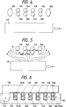
- Figures 1 and 2 are respectively side and plan views of a schematic arrangement diagram of an apparatus for producing optical fiber couplers.
- Reference numerals 1aA to 1dA and 2aA to 2dA represent optical fiber strands, 3aA and 3bA rectifier rods, 4A a gas burner, 5aA to 5dA and 6aA to 6dA optical fibers, 7aA and 7bA optical fiber fixing jigs, 8aA and 8bA optical fiber strand fixing jigs, 9aA and 9bA elongating tables, and 10aA and 10bA rectifier rods supporting members.
- the optical fiber strands 2aA to 2dA are disposed under the optical fiber strands 1aA to 1dA so that they are not shown in Figure 2.
- the first and second optical fibers 5aA to 5dA and 6aA to 6dA are fixed, by the optical fiber fixing jigs 7aA and 7bA, to the elongating tables 9aA and 9bA and held in position such that they are parallel and in tight contact with each other.
- the optical fiber strands 1aA to 1dA obtained by removing the coating of the first optical fibers and the optical fiber strands 2aA to 2dA obtained by removing the coatings of the second optical fibers are fixed, by the optical fiber strand fixing jigs 8aA and 8bA, so as to be in tight contact with each other.
- the rectifier rods 3aA and 3bA supported movably by the rectifier rod supporting members 10aA and 10bA are disposed in predetermined positions outside the optical fiber strands 1aA to 1dA and 2aA to 2dA.
- the optical fiber strands 1aA to 1dA and 2aA to 2dA are heated by use of the gas burner 4A so that 1aA and 2aA, 1bA and 2bA, 1cA and 2cA, and 1dA and 2dA are welded integrally with each other, respectively.
- the integrated optical fiber strands 1aA and 2aA, 1bA and 2bA, 1cA and 2cA, and 1dA and 2dA are heated by use of the gas burner 4A and the rectifier rods 3aA and 3bA are removed, and the elongating table 9aA is moved left while the elongating table 9bA is moved right to thereby perform elongation.
- a laser diode (LD) light source is connected to one end of the optical fiber 5aA while power meters are connected to the other-side ends of the optical fibers 5aA and 6aA to thereby monitor light propagating through the fibers.
- the elongating operation is stopped when the intensities of light emitted from the optical fibers 5aA and 6aA become equal to each other.
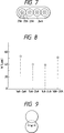
- Figure 3 is a front schematic diagram of the structure of an optical fiber strand fixing jig.
- Reference numeral 11A represents a body member, 12A a pressing member, 13A groove portions, 14A spacer portions, and 15A a pivot.
- the optical fiber strands 1aA to 1dA and 2aA to 2dA accommodated in the groove portions 13A are shown in section.
- the groove portions 13A in the body member 11A are formed with distances so that the protective coatings of the optical fibers can contact. Accordingly, the optical fiber strands are fixed in parallel by the optical fiber strand fixing jig 8aA or 8bA.
- the optical fibers 5aA to 5dA are fixed with their protective coatings in contact with each other in the optical fiber fixing jig 7aA or 7bA as described in Figure 1.
- the outer diameter of each of optical fiber protective coatings is 250 ⁇ m
- the diameter of each of the optical fiber strands is 125 ⁇ m
- the width of each of the groove portions 13A is selected to be 125 ⁇ m
- the width of each of the spacer portions 14A between the groove portions is selected to be 125 ⁇ m.
- the groove portions 13A may be formed by cutting the body member 11A, or the spacer portions may be formed by burying piano wires in a upper surface of the body member 11A which is made plane.
- FIG 4 shows an arrangement of rectifier rods.
- circular quartz glass rods were used as the rectifier rods 3aA and 3bA.
- the material and shape of the rectifier rods are not limited to this embodiment.
- desired materials for example, ceramic materials such as alumina, zirconium, and so on, may be used instead of quartz glass.
- the sectional shape is not limited to a circular one, but preferably the section of each rectifier rod is formed of a curved line to make the flow of gas stable in order to obtain a stable rectifying effect.
- the heating may be carried out with the rectifier rods 3aA and 3bA being left as they are during elongating. In this way, more uniform heating can be carried out and it becomes possible to obtain more uniform characteristics of the optical fiber couplers.
- rod members 3aA and 3bA are disposed on both the outsides of the first and second optical fiber strands 1aA to 1dA and 2aA to 2dA and heating is carried out in this state.
- the rod members hereinafter referred to as "rectifier rods"
- the flow of gas surrounding the optical fiber strands 1aA, 1dA, 2aA and 2dA at the end portions is made weak enough so that a plurality of optical fiber strands are heated uniformly.
- each optical fiber coupler had the degree of coupling of 50 ⁇ 2%, so that it was possible to produce optical fiber couplers having uniform characteristics.
- the optical fibers are not limited to single-core optical fibers.
- Tape-like optical fiber units such as shown in Figure 7 and in Figure 16, may be used as one or both of the optical fiber group 1aA to 1dA and the optical fiber group 2aA to 2dA.
- first and second tape-like eight (8) - core optical fiber units were used as optical fibers so as to produce eight optical fiber couplers en bloc. That is, the optical fibers 5aA to 5dA and 6aA to 6dA of Figures 1 and 2 were replaced by coated optical fibers 5aA to 5hA and 6aA to 6hA of the tape-like optical fiber units (see Figures 17 and 18), and the optical fiber strands 1aA to 1dA and 2aA to 2dA of Figure 1 were replaced by 1aA to 1hA and 2aA to 2hA.
- the coated optical fibers used in the tape-like optical fiber units were optical fibers designed for 1.3 ⁇ m band communication.
- the eight optical fiber strands 1aA to 1hA each having an outer diameter of 125 ⁇ m were etched so as to reduce the outer diameter by use of a 10% fluoric acid solution so that the outer diameter becomes 115 ⁇ m.
- the optical fiber strands 2aA to 2hA of the second tape-like optical fiber unit were not etched so that they were left as they were in a condition where the coating was removed.
- These first and second tape-like optical fiber units were fixed in position using the optical fiber fixing jigs 7aA and 7bA, and the upper and lower optical fiber strands were tightly contacted and fixed by use of the optical fiber fixing jigs 8aA and 8bA.
- both of the rectifier rods 3aA and 3bA were set, and elongating was carried out by moving the elongating table 9aA left and the elongating table 9bA right while the integrated optical fiber strands 1aA to 1hA and 2aA to 2hA were heated using the gas burner 4A.
- an LD light source of a wave length of 1.31 ⁇ m was connected to one end of the optical fiber 5aA
- an LD light source of a wave length of 1.55 ⁇ m was connected to one end of the optical fiber 5bA
- power meters were connected to the other-side ends of the optical fibers 5aA, 5bA, 6aA and 6bA respectively.
- INT1 the intensity of light emitted from the optical fiber 5aA
- INT2 the intensity of light emitted from the optical fiber 6aA
- INT3 the intensity of light emitted from the optical fiber 5bA
- INT4 the intensity of light emitted from the optical fiber 6bA.
- the degree of coupling was measured upon the thus obtained eight optical fiber couplers 1aA-2aA, 1bA-2bA, 1cA-2cA, 1dA-2dA, 1eA-2eA, 1fA-2fA, 1gA-2gA and 1hA-2hA.
- Each optical fiber coupler had the degree of coupling 50 ⁇ 2% at the wave length of 1.31 ⁇ m, and also 50 ⁇ 2% at the wave length of 1.55 ⁇ m. Thus, it could be confirmed that they showed uniform characteristics in each wave length.
- optical fiber couplers produced in the second embodiment were wide band optical fiber couplers the degrees of coupling of which were equal with respect to the wave lengths 1.31 ⁇ m and 1.55 ⁇ m.
- An advantage of the production method according to the present invention is that because optical fiber couplers having the same characteristics can be produced at the same time, the characteristics at a plurality of wave lengths can be monitored without using a combining/branching filter if only a pair of a light source and a photodetector are attached to a plurality of optical fibers.
- the diameters of optical fiber strands of one of the optical fiber units were reduced by etching in order to make the degree of coupling of optical fiber couplers be wide band in the second embodiment.
- it is possible to apply other generally known methods such as a method of using optical fibers having different strand diameters, a method of elongating one optical fiber group in advance, a method of using optical fibers having cores different in diameter, a method of using optical fibers having cores different in refractive index, and so on.
- glass rods having a shape similar to optical fiber strands were used as rectifier rods.
- First and second tape-like four-core optical fiber units were used as optical fibers to produce four optical fiber couplers en bloc.
- Each of the coated optical fibers in each tape-like optical fiber unit was an SM optical fiber having cut-off of 0.75 ⁇ m.
- Figure 6 is a front view illustrating the schematic structure of an example of an optical fiber strand fixing jig similar to that illustrated in Figure 3.
- the reference numerals 16aA, 16bA, 17aA and 17bA represent rectifier rods, the sections of which are illustrated in the same manner as optical fiber strands 1aA to 1dA and 2aA to 2dA.
- the quartz glass rods 16aA and 16bA each having an outer diameter of 125 ⁇ m were disposed as rectifier rods on the opposite sides of the optical fiber strands 1aA to 1dA of the first tape-like optical fiber unit, and the quartz glass rods 17aA and 17bA each having an outer diameter of 125 ⁇ m were disposed as rectifier rods on the opposite sides of the optical fiber strands 2aA to 2dA of the second tape-like optical fiber unit.
- the rectifier rods 16aA, 16bA, 17aA and 17bA were fixed to groove portions 13A of optical fiber strand fixing jigs. According to Figures 1 and 2, the rectifier rods are fixed by the optical fiber strand fixing jigs 8aA and 8bA.
- the optical fiber strands 1aA to 1dA and 2aA to 2dA were heated by the gas burner 4A to thereby carry out welding and elongating operation.
- An LD light source of wave length of 0.85 ⁇ m had been connected to one end of the optical fiber 5aA, and photodetectors had been connected to the other-side ends of the optical fibers 5aA and 6aA. Elongating was stopped when the respective intensities of light emitted from the optical fibers 5aA and 6aA became equal to each other.
- the degree of coupling in each of the thus obtained four optical fiber couplers was in the range of 50+2%, and the uniform characteristics could be confirmed.
- glass rods having the same structure as optical fibers are used as rectifier rods, and these glass rods are also welded and elongated in the same manner as the optical fibers.
- optical fibers per se can be used as rectifier rods.
- Figures 10 and 11 are respectively side and plan views of a schematic arrangement diagram of an apparatus for producing optical fiber couplers, for use in another embodiment of the method of producing optical fiber couplers according to the present invention.
- Reference numerals laB to 1dB and 2aB to 2dB represent optical fiber strands, 3B a gas burner, 4aB to 4dB and 5aB to 5dB optical fibers, 6aB and 6bB optical fiber fixing jigs, 7aB and 7bB optical fiber strand fixing jigs, and 8aB and 8bB elongating tables.
- the optical fiber strands 2aB to 2dB are disposed under the optical fiber strands 1aB to 1dB so that they are not shown in Figure 11.
- the first and second optical fibers 4aB to 4dB and 5aB to 5dB are fixed, by the optical fiber fixing jigs 6aB and 6bB, to the elongating tables 8aB and 8bB so that they are parallel with each other with intervals therebetween. Further, the optical fiber strands 1aB to 1dB obtained by removing the coating of the first optical fibers and the optical fiber strands 2aB to 2dB obtained by removing the coatings of the second optical fibers are fixed, by the optical fiber strand fixing jigs 7aB and 7bB, so as to be in contact tightly with each other. The gaps between the optical fiber strands 1aB - 1dB and 2aB - 2dB are fixed such that a heating gas flow flows uniformly through the gaps between the optical fiber strands as described above.
- the optical fiber strands 1aB to 1dB and 2aB to 2dB are heated by use of the gas burner 3B so that laB and 2aB, 1bB and 2bB, 1cB and 2cB, and 1dB and 2dB are welded integrally with each other, respectively. Thereafter, the integrated optical fiber strands 1aB and 2aB, 1bB and 2bB, 1cB and 2cB, and 1dB and 2dB are heated by use of the gas burner 3B, and the elongating table 9aB is moved left while the elongating table 9bB is moved right to thereby perform elongation.
- a laser diode (LD) light source is connected to one end of the optical fiber 5aB while power meters are connected to the other-side ends of the optical fibers 5aB and 6aB to thereby monitor output lights.
- the elongating operation is stopped when the intensities of light emitted from the optical fibers 5aB and 6aB become equal to each other.
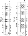
- Figure 12 is a front view illustrating the schematic structure of an example of the optical fiber strand fixing jigs.
- the reference numeral 11B represents a body member, 12B a pressing member, 13B groove portions, 14B spacer portions, and 15B a pivot.
- the optical fiber strands 1aB to 1dB and 2aB to 2dB accommodated in the groove portions 13B are shown in section.
- the groove portions 13B in the body member 11B are formed with spacer portions 14B so that a heating gas flow flows uniformly through each of the gaps between the optical fiber strands.
- each of optical fiber protective coatings is 250 ⁇ m
- the diameter of each of the optical fiber strands is 125 ⁇ m
- the width of each of the groove portions 13B is selected to be 125 ⁇ m
- the width of each of the spacer portions 14B between the groove portions is selected to be 250 ⁇ m in order to make each of the gaps between the optical fiber strands be 250 ⁇ m.
- the groove portions 13B may be formed by cutting the body member 11B, or the spacer portions may be formed by burying piano wires in an upper surface of the body member 11B which is made plane.
- Figure 13 is a front view schematically showing another configuration of a fixing jig.
- Reference numeral 16B represents a body member, 17B a pressing member, 18B groove portions, 19B spacer portions, and 20B a pivot.
- the optical fibers 4aB - 4dB, and 5aB and 5dB accommodated in the groove portions 18B are shown in section.
- the groove portions 18B in the body member 16B are formed with the spacer portions 19B at intervals such that the center lines of the respective groove portions coincide with the center lines of the respective groove portions of the optical fiber strand fixing jig.
- the groove portions 18B may be formed by cutting the body member 16B, or the spacer portions 19B may be formed by burying piano wires in an upper surface of the body member 16B which is made plane. In a state that two optical fiber strands are accommodated in each groove portion 18B, the pressing member 17B is turned down around the pivot 20B so as to press and fix the optical fibers from the upside.
- optical fiber couplers were produced by use of the above-mentioned apparatus for producing optical fiber couplers shown in Figures 10 and 11.
- Single-mode (SM) optical fibers for 1.3 ⁇ m band communication were used as the optical fibers 4aB to 4dB and 5aB to 5dB.
- Each of the gaps between the optical fiber strands 1aB - 1dB and 2aB - 2dB was made to be 250 ⁇ m.
- an LD light source of a wave length of 1.31 ⁇ m was used as a light source for monitoring the ratio of branching, and the elongating operation was stopped when the emitted light intensities became equal to each other, in the same manner as mentioned above.
- each optical fiber coupler had the degree of coupling of 50 ⁇ 2%, so that it was possible to produce optical fiber couplers having uniform characteristics.
- Optical fibers are not limited to single-core optical fibers. Tape-like optical fibers may be used as one or both of the optical fiber group 1aB to 1dB and the optical fiber group 2aB to 2dB.
- tape-like four (4)-core optical fiber units were used as optical fibers so as to produce four optical fiber couplers en bloc.
- the coated optical fibers used in the tape-like optical fiber units were optical fibers for 1.3 ⁇ m band communication.
- Figure 16 is a sectional view of the tape-like four-core optical fiber unit.
- the outer diameter of each optical fiber strand constituted by a core 21B and a clad 22B is 125 ⁇ m and the outer diameter of the coated optical fiber obtained by covering the optical strand with a protective coating 23B.
- the coated optical fibers are arranged in plane at intervals of 375 ⁇ m and covered with a coating layer 24B so as to make the coated optical fibers integrated flatly. Accordingly, each gap between the coating layers is 125 ⁇ m, and each gap between the clads is 250 ⁇ m.
- the four optical fiber strands laB to 1dB each having an outer diameter of 125 ⁇ m were etched so as to reduce the outer diameter by use of a 10% fluoric acid solution so that the outer diameter becomes 115 ⁇ m.
- the optical fiber strands 2aB to 2dB of the second tape-like optical fiber unit were not subjected to etching so that they were left as they were in a condition where the coating was removed.
- These first and second tape-like optical fiber units were fixed by use of the optical fiber fixing jigs 6aB and 6bB, and the upper and lower optical fiber strands were tightly contacted and fixed by use of the optical fiber fixing jigs 7aB and 7bB.
- Heat elongating operation was carried out by moving the elongating table 8aB left and the elongating table 8bB right after the integrated optical fiber strands 1aB to 1dB and 2aB to 2dB were heated by use of the gas burner 3B.
- an LD light source of a wave length of 1.31 ⁇ m was connected to one end of the optical fiber 4aB
- an LD light source of a wave length of 1.55 ⁇ m was connected to one end of the optical fiber 5bB
- power meters were connected to the other-side ends of the optical fibers 5aB, 5bB, 6aB and 6bB respectively.
- INT5 the intensity of light emitted from the optical fiber 4aB
- INT6 the intensity of light emitted from the optical fiber 5aB
- INT7 the intensity of light emitted from the optical fiber 4bB
- INT8 the intensity of light emitted from the optical fiber 5bB.
- the degree of coupling was measured upon the thus obtained four optical fiber couplers 1aB-2aB, 1bB-2bB, 1cB-2cB, and 1dB-2dB.
- Each optical fiber coupler had the degree of coupling 50 ⁇ 2% at the wave length of 1.31 ⁇ m, and also 50 ⁇ 2% at the wave length of 1.55 ⁇ m. Thus, it could be confirmed that they showed uniform characteristics in each wave length.
- the optical fiber couplers produced in the fifth embodiment were wide band optical fiber couplers, the degrees of coupling of which were equal with respect to the wave lengths 1.31 ⁇ m and 1.55 ⁇ m.
- optical fiber couplers having the same characteristics can be produced at the same time, the characteristics at a plurality of wave lengths can be monitored without using a combining/branching filter if only a pair of a light source and a photodetector are attached to a plurality of optical fibers, and it is not necessary to constitute a complicated monitor system.
- the diameters of optical fiber strands of one of the optical fiber units were reduced by etching in order to make the degree of coupling of optical fiber couplers be wide band in the fifth embodiment.
- it is possible to apply other generally known methods such as a method of using optical fibers having different strand diameters, a method of elongating one optical fiber group in advance, a method of using optical fibers having cores different in diameter, a method of using optical fibers having cores different in refractive index, and so on.
- optical fiber couplers were produced by the production apparatus shown in Figure 10 by use of tape-like four-core optical fiber units obtained by making SM optical fibers having cut-off of 0.75 ⁇ m, a strand diameter of 125 ⁇ m, and a coating diameter of 250 ⁇ m into the form-like tapes. Since each tape-like optical fiber unit has a usual tape-like optical fiber structure in this embodiment, it is necessary to widen each interval between optical fiber strands in the portion in which the coating is removed to 250 ⁇ m.
- the separated single-core optical fibers were arranged by use of the optical fiber fixing jigs 6aB and 6bB and the optical fiber strand fixing jigs 7aB and 7bB, and then welding and elongating operations were performed.
- the optical fiber fixing jigs are similar to those which were described in Figure 13, and the optical fiber strand fixing jigs are similar to those which were described in Figure 12.
- Figure 14 is a diagram showing heating of the fiber strands.
- Figure 15 is a front view schematically illustrating an optical fiber fixing jig that is suitable.
- heating operation is carried out in a condition that the first optical fiber strands 1aB - 1dB and the second optical fiber strands 2aB - 2dB are arranged so that the gaps between the first optical fiber strands 1aB - 1dB and the second optical fiber strands 2aB - 2dB allow a heating gas flow to uniformly flow through the gaps. Accordingly, the gas flow flows between the optical fiber strands to make it possible to heat all the optical fiber strands uniformly so that optical couplers having the same characteristics can be obtained.
- the intervals of the optical fiber strands may be selected so as to form gaps between alternate optical fiber strands so that the gaps allow the heating gas flow to flow uniformly therethrough.
- rectifier rods may be used in the elongating operation as well as in the welding operation, so that it is possible to elongate optical fibers while maintaining a uniform temperature.
- a tape-like multi-core optical fiber unit ribbon fiber
- a method of using a tape-like optical fiber unit in which optical fiber strands are formed so that each of the gaps therebetween is 250 ⁇ m or more and a method in which a tape-like optical fiber unit having an ordinary structure is used and the optical fibers only at the portion where the coating is removed are separated from each other so as to be single-core optical fibers and arranged so that each of the gaps therebetween is 250 ⁇ m or more are advantageous.
- an LD light source of wave length 0.85 ⁇ m was connected to one end of an optical fiber 4aB, and light power meters were connected with the other side ends of the optical fibers 4aB and 5aB, so that the elongating operation was performed while the emitted light intensities were monitored, and the elongating operation was stopped when the intensities of light emitted from the respective optical fibers 4aB and 5aB became equal to each other.
- the degree of coupling in each obtained optical fiber coupler was 50 ⁇ 2%, and it was confirmed that the couplers had uniform characteristics.
- optical fiber couplers were produced en bloc by the production apparatus shown in Figure 10 by use of tape-like eight-core optical fiber units as optical fibers.
- the coated optical fibers used in the tape-like optical fiber units were optical fibers for 1.3 ⁇ m band communication. Since each of the tape-like optical fiber units had a usual structure in this embodiment, each tape-like optical fiber unit was separated into single-core optical fibers at positions before and after the portion in which the coating had been removed, and, then, the separated single-core optical fibers were arranged by use of the optical fiber fixing jigs 6aB and 6bB and the optical fiber strand fixing jigs 7aB and 7bB.
- each optical fiber strand of each tape-like eight-core optical fiber unit used in this embodiment was 125 ⁇ m, and the outer diameter of each coated optical fiber obtained by covering each optical fiber strand with a protective coating was 250 ⁇ m.
- the optical fibers were arranged so that the interval between alternate optical fiber strand was not shorter than 250 ⁇ m, for example, 500 ⁇ m.
- Figure 17 is a front view illustrating the schematic structure of an example of the optical fiber strand fixing jig
- Figure 18 is a front view illustrating the schematic structure of an example of the optical fiber fixing jig.
- the coated optical fibers are fixed such that two coated optical fibers are arranged with their coatings contacting with each other, the next two coated optical fibers are arranged with their coatings contacting with each other, and the same rule applies correspondingly to the following is applies. Accordingly, the gap between the two optical fiber strands of every two optical fibers with their coatings contacting with each other is 125 ⁇ m.
- the distance between the center lines of adjacent two optical fibers with their coatings separated from each other is 625 ⁇ m, and the gap between the respective coatings of adjacent two optical fibers with their coatings separated from each other is 375 ⁇ m. Accordingly, the gap between the respective optical fiber strands of adjacent two optical fibers with their coatings separated from each other is 500 ⁇ m.
- an LD light source of wave length 1.55 ⁇ m was connected to one end of an optical fiber 4aB, and power meters were connected to the other side ends of the optical fibers 4aB and 5aB, so that the elongating operation was performed while the emitted light intensities were monitored, and the elongating operation was stopped when the intensities of light emitted from the respective optical fibers 4aB and 5aB became equal to each other.
- the degree of coupling was 50 ⁇ 2% in each optical fiber coupler, and it was confirmed that uniform characteristics cculd be obtained.
Priority Applications (1)
| Application Number | Priority Date | Filing Date | Title |
|---|---|---|---|
| EP96120983A EP0769709B1 (de) | 1992-11-05 | 1993-11-04 | Verfahren zur Herstellung von faseroptischen Kopplern |
Applications Claiming Priority (4)
| Application Number | Priority Date | Filing Date | Title |
|---|---|---|---|
| JP321323/92 | 1992-11-05 | ||
| JP321324/92 | 1992-11-05 | ||
| JP4321324A JP2800601B2 (ja) | 1992-11-05 | 1992-11-05 | 光ファイバカプラの製造方法 |
| JP32132392A JPH06148461A (ja) | 1992-11-05 | 1992-11-05 | 光ファイバカプラの製造方法 |
Related Child Applications (1)
| Application Number | Title | Priority Date | Filing Date |
|---|---|---|---|
| EP96120983A Division EP0769709B1 (de) | 1992-11-05 | 1993-11-04 | Verfahren zur Herstellung von faseroptischen Kopplern |
Publications (1)
| Publication Number | Publication Date |
|---|---|
| EP0596502A1 true EP0596502A1 (de) | 1994-05-11 |
Family
ID=26570433
Family Applications (2)
| Application Number | Title | Priority Date | Filing Date |
|---|---|---|---|
| EP96120983A Expired - Lifetime EP0769709B1 (de) | 1992-11-05 | 1993-11-04 | Verfahren zur Herstellung von faseroptischen Kopplern |
| EP93117919A Withdrawn EP0596502A1 (de) | 1992-11-05 | 1993-11-04 | Herstellungsverfahren für faseroptische Koppler |
Family Applications Before (1)
| Application Number | Title | Priority Date | Filing Date |
|---|---|---|---|
| EP96120983A Expired - Lifetime EP0769709B1 (de) | 1992-11-05 | 1993-11-04 | Verfahren zur Herstellung von faseroptischen Kopplern |
Country Status (3)
| Country | Link |
|---|---|
| US (2) | US5417734A (de) |
| EP (2) | EP0769709B1 (de) |
| DE (1) | DE69328735T2 (de) |
Cited By (3)
| Publication number | Priority date | Publication date | Assignee | Title |
|---|---|---|---|---|
| EP0687930A3 (de) * | 1994-06-14 | 1996-03-27 | Sumitomo Electric Industries | Herstellungsmethode für faseroptische Koppler |
| US5695540A (en) * | 1992-11-05 | 1997-12-09 | Sumitomo Electric Industries, Ltd. | Method of spacing fibers of optical fiber tapes and coupling the fibers |
| EP0930278A2 (de) * | 1997-12-29 | 1999-07-21 | Lucent Technologies Inc. | Verfahren und Vorrichtung zum Herstellen von Faserbündeln |
Families Citing this family (3)
| Publication number | Priority date | Publication date | Assignee | Title |
|---|---|---|---|---|
| JP2002286963A (ja) * | 2001-03-23 | 2002-10-03 | Sumitomo Electric Ind Ltd | 光ファイバの融着接続方法 |
| US8485735B2 (en) * | 2008-12-19 | 2013-07-16 | US Conec, Ltd | Field install fiber clip and method of use |
| JP2020071419A (ja) * | 2018-11-01 | 2020-05-07 | 住友電気工業株式会社 | 光ファイバの融着接続方法及び融着接続装置 |
Citations (2)
| Publication number | Priority date | Publication date | Assignee | Title |
|---|---|---|---|---|
| GB2204145A (en) * | 1987-02-21 | 1988-11-02 | Nippon Telegraph & Telephone | Fused fiber coupler having two optical fibre groups in parallel planes |
| EP0350900A2 (de) * | 1988-07-13 | 1990-01-17 | Sumitomo Electric Industries, Ltd. | Methode zur Herstellung eines optischen Verzweigungs- und Kopplungselements |
Family Cites Families (19)
| Publication number | Priority date | Publication date | Assignee | Title |
|---|---|---|---|---|
| US4028162A (en) * | 1974-10-24 | 1977-06-07 | Bell Telephone Laboratories, Incorporated | Method of splicing pairs of arrayed or individual fibers utilizing optical fiber aligning grooves |
| FR2445972A1 (fr) * | 1979-01-03 | 1980-08-01 | Lyonnaise Transmiss Optiques | Dispositif de soudage de plusieurs fibres optiques bout a bout par nappes et procede de soudage a l'aide de ce dispositif |
| FR2489969B1 (fr) * | 1980-09-05 | 1985-07-05 | Socapex | Outillage servant a preparer des cables optiques a plusieurs fibres en vue de leur aboutement fibre a fibre |
| AU569803B2 (en) * | 1984-09-06 | 1988-02-18 | Hitachi Limited | Optical fibre star coupler |
| JPS61145521A (ja) * | 1984-12-19 | 1986-07-03 | Dainippon Printing Co Ltd | 光フアイバ投受光部の製造方法 |
| JPS623208A (ja) * | 1985-06-28 | 1987-01-09 | Sumitomo Electric Ind Ltd | 光フアイバの接続方法 |
| GB8611361D0 (en) * | 1986-05-09 | 1986-06-18 | Bicc Plc | Splicing optical fibre ribbon |
| DE3786916T2 (de) * | 1986-11-14 | 1993-11-11 | Commw Of Australia | Herstellung von faseroptischen komponenten. |
| DE3639458A1 (de) * | 1986-11-18 | 1988-05-19 | Standard Elektrik Lorenz Ag | Verfahren und vorrichtung zum loesbaren befestigen von blanken glasfasern in einer spleissvorrichtung |
| JPH01120510A (ja) | 1987-11-05 | 1989-05-12 | Nippon Telegr & Teleph Corp <Ntt> | 光ファイバカップラの製造方法 |
| JPH0782136B2 (ja) * | 1987-02-21 | 1995-09-06 | 日本電信電話株式会社 | 光フアイバカツプラならびにその製造方法および製造装置 |
| US4763272A (en) * | 1987-03-29 | 1988-08-09 | The United States Of America As Represented By The Secretary Of The Navy | Automated and computer controlled precision method of fused elongated optical fiber coupler fabrication |
| CA1308937C (en) * | 1988-01-11 | 1992-10-20 | Francois Bilodeau | Fabrication technique for low-loss fused taper directional couplers and pressure sensor produced thereby |
| US5167685A (en) * | 1988-11-21 | 1992-12-01 | Sumitomo Electric Industries, Ltd. | Method for manufacturing a fiber type coupler |
| US5046804A (en) * | 1988-11-21 | 1991-09-10 | Sumitomo Electric Industries, Ltd. | Method for manufacturing a fiber type coupler |
| JPH0372304A (ja) * | 1989-08-11 | 1991-03-27 | Japan Aviation Electron Ind Ltd | 光結合器の製造方法 |
| JPH03154010A (ja) * | 1989-11-13 | 1991-07-02 | Sumitomo Electric Ind Ltd | 光フアイバカプラの製造方法 |
| US5205851A (en) * | 1990-10-12 | 1993-04-27 | Sumitomo Electric Industries, Ltd. | Method and apparatus for producing optical fiber coupler |
| EP0769709B1 (de) * | 1992-11-05 | 2000-05-24 | Sumitomo Electric Industries, Ltd. | Verfahren zur Herstellung von faseroptischen Kopplern |
-
1993
- 1993-11-04 EP EP96120983A patent/EP0769709B1/de not_active Expired - Lifetime
- 1993-11-04 US US08/145,509 patent/US5417734A/en not_active Expired - Fee Related
- 1993-11-04 EP EP93117919A patent/EP0596502A1/de not_active Withdrawn
- 1993-11-04 DE DE69328735T patent/DE69328735T2/de not_active Expired - Fee Related
-
1995
- 1995-05-15 US US08/441,304 patent/US5695540A/en not_active Expired - Lifetime
Patent Citations (2)
| Publication number | Priority date | Publication date | Assignee | Title |
|---|---|---|---|---|
| GB2204145A (en) * | 1987-02-21 | 1988-11-02 | Nippon Telegraph & Telephone | Fused fiber coupler having two optical fibre groups in parallel planes |
| EP0350900A2 (de) * | 1988-07-13 | 1990-01-17 | Sumitomo Electric Industries, Ltd. | Methode zur Herstellung eines optischen Verzweigungs- und Kopplungselements |
Cited By (4)
| Publication number | Priority date | Publication date | Assignee | Title |
|---|---|---|---|---|
| US5695540A (en) * | 1992-11-05 | 1997-12-09 | Sumitomo Electric Industries, Ltd. | Method of spacing fibers of optical fiber tapes and coupling the fibers |
| EP0687930A3 (de) * | 1994-06-14 | 1996-03-27 | Sumitomo Electric Industries | Herstellungsmethode für faseroptische Koppler |
| EP0930278A2 (de) * | 1997-12-29 | 1999-07-21 | Lucent Technologies Inc. | Verfahren und Vorrichtung zum Herstellen von Faserbündeln |
| EP0930278A3 (de) * | 1997-12-29 | 1999-09-29 | Lucent Technologies Inc. | Verfahren und Vorrichtung zum Herstellen von Faserbündeln |
Also Published As
| Publication number | Publication date |
|---|---|
| EP0769709A2 (de) | 1997-04-23 |
| EP0769709B1 (de) | 2000-05-24 |
| EP0769709A3 (de) | 1997-05-07 |
| US5695540A (en) | 1997-12-09 |
| DE69328735D1 (de) | 2000-06-29 |
| DE69328735T2 (de) | 2000-09-07 |
| US5417734A (en) | 1995-05-23 |
Similar Documents
| Publication | Publication Date | Title |
|---|---|---|
| EP0193224B1 (de) | Herstellung von optischen Fiberkopplern | |
| CA1321072C (en) | Method of manufacturing optical branching and coupling device | |
| EP0326988B1 (de) | Verfahren zum Bestimmen der Strahlungsverluste von Faserverbindungen | |
| US5171345A (en) | Manufacturing method of an optical fiber coupler | |
| EP0525743A1 (de) | Methode zur Verstärkung eines faseroptischen Kopplers | |
| EP0544024B1 (de) | Herstellungs- und Messmethode von integriert-optischen Komponenten | |
| EP0769709B1 (de) | Verfahren zur Herstellung von faseroptischen Kopplern | |
| EP0320978A2 (de) | Verfahren zum Messen von an optische Fasern zugeführten Wärmemengen | |
| JPS6080806A (ja) | 光分岐器及びその製造方法 | |
| JPH10246838A (ja) | 光ファイバアレイ装置 | |
| US4662743A (en) | Method of measuring the geometry of optical fibers | |
| CN115931021A (zh) | 一种光纤传感器、其制备方法及传感装置 | |
| JP4172097B2 (ja) | ロッドレンズ付き光ファイバ配列部品の製造方法 | |
| JP2800601B2 (ja) | 光ファイバカプラの製造方法 | |
| KR20020052988A (ko) | 리본 섬유 및 그 제조 방법과, 이것을 이용한 광섬유 어레이 | |
| JPH06148461A (ja) | 光ファイバカプラの製造方法 | |
| CN212568471U (zh) | 一种双通道光纤spr传感器 | |
| CN218066355U (zh) | 一种光纤弯曲损耗波长与spr的多通道曲率传感器 | |
| CN220136519U (zh) | 一种高灵敏度的温度传感器 | |
| JP2892023B2 (ja) | 光ファイバカプラ | |
| JP2003526114A (ja) | シングルモードファイバのオンライン減衰装置と、その製造方法 | |
| JPH037061B2 (de) | ||
| JPH0658289B2 (ja) | 光フアイバの測定法 | |
| JPH08122528A (ja) | 光パワー測定用光ファイバブロックアレイ | |
| CN115903125A (zh) | 拼接结构的长周期光纤光栅及光纤弯曲传感器 |
Legal Events
| Date | Code | Title | Description |
|---|---|---|---|
| PUAI | Public reference made under article 153(3) epc to a published international application that has entered the european phase |
Free format text: ORIGINAL CODE: 0009012 |
|
| AK | Designated contracting states |
Kind code of ref document: A1 Designated state(s): DE ES FR GB IT NL |
|
| 17P | Request for examination filed |
Effective date: 19940714 |
|
| 17Q | First examination report despatched |
Effective date: 19960424 |
|
| GRAG | Despatch of communication of intention to grant |
Free format text: ORIGINAL CODE: EPIDOS AGRA |
|
| GRAG | Despatch of communication of intention to grant |
Free format text: ORIGINAL CODE: EPIDOS AGRA |
|
| GRAH | Despatch of communication of intention to grant a patent |
Free format text: ORIGINAL CODE: EPIDOS IGRA |
|
| STAA | Information on the status of an ep patent application or granted ep patent |
Free format text: STATUS: THE APPLICATION IS DEEMED TO BE WITHDRAWN |
|
| 18D | Application deemed to be withdrawn |
Effective date: 19990330 |