EP0593061B1 - Système pour l'analyse de l'occlusion dentaire - Google Patents
Système pour l'analyse de l'occlusion dentaire Download PDFInfo
- Publication number
- EP0593061B1 EP0593061B1 EP93116652A EP93116652A EP0593061B1 EP 0593061 B1 EP0593061 B1 EP 0593061B1 EP 93116652 A EP93116652 A EP 93116652A EP 93116652 A EP93116652 A EP 93116652A EP 0593061 B1 EP0593061 B1 EP 0593061B1
- Authority
- EP
- European Patent Office
- Prior art keywords
- occlusion
- color
- pressure
- pressures
- scanner
- Prior art date
- Legal status (The legal status is an assumption and is not a legal conclusion. Google has not performed a legal analysis and makes no representation as to the accuracy of the status listed.)
- Expired - Lifetime
Links
Images


Classifications
-
- A—HUMAN NECESSITIES
- A61—MEDICAL OR VETERINARY SCIENCE; HYGIENE
- A61C—DENTISTRY; APPARATUS OR METHODS FOR ORAL OR DENTAL HYGIENE
- A61C19/00—Dental auxiliary appliances
- A61C19/04—Measuring instruments specially adapted for dentistry
- A61C19/05—Measuring instruments specially adapted for dentistry for determining occlusion
-
- A—HUMAN NECESSITIES
- A61—MEDICAL OR VETERINARY SCIENCE; HYGIENE
- A61C—DENTISTRY; APPARATUS OR METHODS FOR ORAL OR DENTAL HYGIENE
- A61C9/00—Impression cups, i.e. impression trays; Impression methods
- A61C9/004—Means or methods for taking digitized impressions
- A61C9/0046—Data acquisition means or methods
- A61C9/0053—Optical means or methods, e.g. scanning the teeth by a laser or light beam
-
- A—HUMAN NECESSITIES
- A61—MEDICAL OR VETERINARY SCIENCE; HYGIENE
- A61C—DENTISTRY; APPARATUS OR METHODS FOR ORAL OR DENTAL HYGIENE
- A61C9/00—Impression cups, i.e. impression trays; Impression methods
- A61C9/004—Means or methods for taking digitized impressions
Definitions
- the present invention relates to a system for analyzing the occlusion condition of a patient, wherein an occlusion condition diagnosing sheet including therein a pressure-sensitive composite recording sheet structure is used to inspect the occlusion condition of the patient.
- carbon paper has been widely used to know the occlusion condition of the teeth of a patient.
- Carbon paper is inserted between the upper and lower dental arches of the patient; and as the patient bites strongly to occlude the upper and lower teeth, carbon particles adhere on the occlusal surfaces at the portions where the upper and lower teeth are abutted.
- the dentist can diagnose the occlusion condition of the teeth of the patient by observing the positions and areas of the portions to which carbon particles stick.
- the prior art technology has another problem that the dentist must precisely position the detecting sheet, such as carbon paper, by looking into the oral cavity of the patient since there is provided no means for precisely positioning the detecting sheet so as to know the portions, at which upper and lower teeth contact or abut with each other. This leads the problem that the operation efficiency is lowered.
- the detecting sheet such as carbon paper
- the present invention has been accomplished under the circumstances as aforementioned, and the object thereof is to provide an occlusion pressure detecting system for detecting the tooth alignment condition in the dental arch and the distribution of occlusion pressure of a patient simply and precisely to obtain data which can be used as extremely effective data for the precise diagnosis on the occlusion condition and for the determination of treatment course, by a relatively easier operation for the patient on one hand and on the other hand through a simple operation by the dentist.
- the aforementioned object is attained by the provision of a system for analyzing the occlusion condition of a patient having the features of claim 1.
- the image of the dental arch pattern and the image showing the distribution of the density graduations corresponding to the occlusion pressures are displayed on the output means in the overlapping condition.
- the system may have a single scanner which is used as the first scanner at any desired time and also used as the second scanner at the time other than the time duration when it is used to serve as the first scanner.
- the occlusion condition detecting sheet comprises the wax coating layers each having a color different from the color developed on the pressure-sensitive composite recording sheet structure, and more preferably the color of the wax coating layers be complementary to the color developed in the pressure-sensitive composite recording sheet structure so that the colors of the former can be read separately from the color of the latter with ease.
- the color density graduations identifying the occlusion pressures are represented by the varying colors, namely the graduating color densities being stepwisely divided into plural ranges which are represented by a series of varying colors, and the colors identifying the occlusion pressures are displayed on the output means while overlapping with the colored image of the dental arch pattern on each wax coating layer.
- the output means may be operated alternately to display the image of the dental arch pattern and to display the distribution of the occlusion pressures.
- the aforementioned object may also be attained by the provision of a system for analyzing the occlusion condition of a patient having the features of claim 8.
- said processor operates to find the geometric mean of the occlusion pressures in the dental arch of the patient so that the thus found geometric mean is displayed in the condition of overlapping with the image of the tone graduation of the occlusion pressure distribution.
- Fig. 1 is a plan view of the occlusion condition diagnosing sheet used in the first embodiment of the invention
- Fig. 2 is a sectional view showing a portion of the occlusion condition diagnosing sheet used in the first embodiment
- Fig. 3 is a graph showing the interrelation between the applied pressures and the color densities on the pressure-sensitive composite sheet structure used in the first embodiment.
- reference numeral 10 designates a transparent synthetic resin support sheet which is, for example, made of a PET (polyethylene terephthalate) film having a thickness of 25 ⁇ m.
- Reference numeral 12 designates a color developer layer which is formed by coating a dispersion containing montmorillonnite sulfate (obtained by treating acid terra alba (montmorillonnite) with sulfuric acid) in an aqueous sodium hydroxide solution over one face (obverse side) of the support sheet 10, followed by drying.
- Reference numeral 14 designates a color former layer overlaid on the color developer layer 12, and is formed by coating a color forming agent, such as 1-phenyl-1-xylylethane, dispersed in an oil in a microcapsulated condition.
- a color forming agent such as 1-phenyl-1-xylylethane
- the microcapsules of the color former include microcapsules having varied strengths or resistances to rupture to be ruptured upon application of pressure. As some of the capsules are ruptured, depending on the pressure applied on the recording sheet, the color former contained in the ruptured capsules is absorbed together with the oil by the color developer to develop a color, red in the illustrated embodiment. The density of the thus developed color becomes thicker as the applied pressure is increased.
- Fig. 3 shows the change in density D of the developed color in terms of the applied pressure P.
- the pressure-sensitive composite recording sheet used in the invention makes use of coloring upon application of pressure, color development being resulted by the contact between the color former contained in the ruptured microcapsules and the color developer in the color developer layer 12.
- the microcapsules contained in the color former layer 12 are mixture of a group of microcapsules respectively having different wall thicknesses to be ruptured upon application of different pressures. In other words, the number of capsules ruptured by the application of a particular pressure is intentionally differentiated.
- the density of color which is developed by the reaction between the color former flowing out of the ruptured capsules and the color developer, developed by the application of a certain pressure is in some proportional interrelationship with the pressure applied on the pressure-sensitive composite recording sheet 15.
- the coloring agent is a colorless compound which develops some color upon contact with a solid acid, examples being electron-donating organic compounds.
- the color developer is a solid acid, more specifically an electron-accepting solid acid. More detailed description of microcapsules, color formers or coloring agents and color developers which may be used in this invention will be found, for example, in Japanese Patent Publication No. 24852/1982 (corresponding to United States Patent No. 4,002,060) and Japanese Patent Publication No. 16654/1984 (corresponding to United States Patent No. 4,132,112).
- Reference numeral 16 designates a first water-impermeable layer or backside waterproof layer which may be made of a transparent synthetic resin film such as PET film, similar to the film forming the support sheet 10, having a thickness of, for example, 16 ⁇ m.
- a tackifying adhesive is coated on one face, the face opposing to the support sheet 10, of the first water-impermeable layer 16 to form an adhesive layer 18.
- the first water-impermeable layer 16 is liquid-tightly applied on one face (the face opposing to the face to which the color developer layer 12 is applied) of the support sheet 10 through this adhesive layer 18.
- Reference numeral 20 designates a second water-impermeable layer or obverse waterproof layer which may be made of a transparent synthetic resin film such as PET film, similar to the film forming the first water-impermeable layer 16, having a thickness of, for example, 16 ⁇ m.
- This second water-impermeable layer 20 is overlaid on the color former layer 14 and has the peripheral margin sealingly adhering to the adhesive layer 18 applied on the first water-impermeable layer 16. It is desirous that the entire marginal portions of both water-impermeable layers 16 and 20 are sealed under a sufficiently reduced pressure.
- the pressure-sensitive recording sheet 22 used in this embodiment is improved in waterproof property and exhibits high reliability in use, since the pressure-sensitive composite recording sheet structure 15 composed of the support sheet 10, the color developer layer 12 and the color former layer 14 is liquid-tightly sealed by means of the first water-impermeable layer 16 and the second water-impermeable layer 20. Moreover, since one of the water-impermeable layer, the first water-impermeable layer 16 in the illustrated embodiment, is closely adhering to the backside of the support sheet 10, the layer 16 is prevented from displacement relative to and delamination from the support sheet 10. With the construction as aforementioned, the second water-impermeable layer 20 is also prevented from relative displacement from the support sheet 10, since the marginal or peripheral portions thereof are fixedly adhering to the marginal or peripheral portions of the first water-impermeable layer 16.
- the sheet 22 has a generally horseshoe-like pattern to be fitted with the dental arch of the patient, and has the surfaces coated with wax coating layers 24, 26.
- Each of the wax coating layers 24, 26 is formed by uniformly coating a dental paraffin wax (JIS-T-6502) to have a thickness of, for example, 0.35 ⁇ 0.3 mm.
- the occlusion condition diagnosing sheet 28 is inserted into the opened mouth of the patient so that it is engaged evenly with the dental arch. As the patient bites the sheet 28 gently, the shapes of teeth in the entire dental arches are recorded as the concaved and convexed traces on these wax coating layers 24, 26. At the same time, the occlusion pressures between the upper and lower occluding teeth are applied on the pressure-sensitive composite recording sheet structure 15 so that the portions on which the pressures are applied are colored, in red in the illustrated example, to have densities varied in proportion to the applied pressures.
- the dentist pulls out of the patient's mouth the occlusion condition diagnosing sheet 28 having the wax coating layers 24, 26, on which the dental arch patterns are traced, and including the pressure-sensitive composite sheet structure 15 having portions colored to have color densities in proportion to the applied pressures, and then the sheet 28 is subjected to analysis in the system of the invention.
- the coloring of the sheet structure 15 is complementary to the color of the wax coating layers 24, 26. For instance, when the color developed in the sheet structure 15 is red, the wax coating layers 24, 26 preferebly have a color close to the color complementary to red, e.g. green or bluish green.
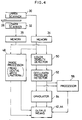
- Fig. 4 is a block diagram showing the structure and operation sequence in the first embodiment of the invention
- Fig. 5 is a similar block diagram showing the structure and operation sequence in the first embodiment of the invention
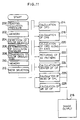
- Fig. 6 is a flow chart showing the operation sequence taking place in the system according to the first embodiment
- Fig. 7 is a photograph displayed on the output display means of the first embodiment.
- reference numeral 30 designates an upper scanner and reference numeral 32 designates a lower scanner. These scanners are color scanners positioned respectively to scan the upper and lower surfaces of the sheet 28 to read the images on the sheet 28.
- each of the scanners 30, 32 scan the opposing surfaces of the sheet 28 for two times, at one time for reading the concaved and convexed image or trace of the upper or lower dental arch recorded on the wax coating layer 24 or 26, and at the other time for reading the color densities of the image recorded on the pressure-sensitive composite recording sheet structure 15.
- each of the scanners 30, 32 serves both as the first scanner for reading the images of dental arch patterns left on the wax coating layers 24, 26 and as the second scanner for reading the color density developed on the pressure-sensitive composite recording sheet structure 15.
- Reference numerals 34, 36 designate memories which store the images read by the scanners 30, 32, the processed images or the data obtained through various processings.
- reference numeral 38 designates a central processing unit (CPU) which is connected to a keyboard 40, a cathode ray tube (CRT) 42 which is used as the output means, and a printer 44 which is also used as the output means. These members are mutually connected through a bus 46.
- the memories 34, 36 and the scanners 30, 32 are also connected to the bus 46.
- Reference numeral 48 designates an image processor by which the images read by the sanners 30, 32 are processed through spatial filtering to be subjected to contour emphasizing, levelling and/or other necessary processings.
- Reference numeral 50 designates a color density detector for detecting the density of coloring on the pressure-sensitive composite recording sheet structure 15.
- Reference numeral 52 designates an occlusion pressure detecting means or detector for receiving the outputs, i.e. the color densities D, from the color density detector 50 to determine the value of occlusion pressures P while referring to the curve showing the interrelation between P and D.
- Reference numeral 54 designates a graduator, which serves as the graduation display means, for determining the graduations or color ranges for respective occlusion pressure ranges. For example, it is possible to designate specified colors for respective occlusion pressure ranges so that the occluding points, at which the upper and lower lower teeth occlude at different pressures, are represented by different colors.
- the pressure ranges are specifically identified as follows:
- Reference numeral 56 designates a processor for calculating the center (geometrical mean) of the occlusion pressures. This processor operates to determine the center, i.e. the geometrical mean G, of the occlusion pressures from the distribution of the occlusion pressures detected by the occlusion pressure detector 52.
- the occlusion condition diagnosing sheet 28 which has been bitten by the patient, is set between the upper and lower scanners 30, 32.
- the concaved and convexed images left on the wax coating layers 24, 26 are read by the scanners 30, 32 (Step 100).
- the images are subjected to contour emphasizing processing and other necessary processings (Step 102), and then stored in the memories 34, 36 (Step 104).
- the colored image (i.e. the occlusal view) on the pressure-sensitive composite recording sheet structure 15 is read by the scanners 30, 32 (Step 106).
- Output signals from the scanners 30, 32 are received by the color density detector 50 by which the densities of colored portions are determined (Step 108).
- the occlusion pressures P corresponding to the densities D are calculated by the occlusion pressure detector 52 while referring to the curve showing the interrelation between P and D (Step 110).
- the thus determined occlusion pressures are converted, respecatively, to different colors each corresponding to a specific pressure range by the graduator 54 (Step 112), and the color graduations are stored in the memories 34, 36 (Step 114).
- the center or geometrical mean G is calculated from the occlusion pressure distribution by the processor 56 (Step 116) and stored in the memories 34, 36 (Step 114).
- the images on the wax coating layers 34, 36 and the distribution pattern of the occlusion pressures P determined from the color densities on the sheet 15, both being stored in the memories 34, 36, are simultaneously fed to the output means 42 (CRT in the embodiment shown in Fig. 5) or 44 (a printer in the embodiment shown in Fig. 5) where they are subjected to desired processing to be displayed or printed in the overlapping condition (Steps 118 and 120).
- the output means 42 CRT in the embodiment shown in Fig. 5
- 44 a printer in the embodiment shown in Fig. 5
- the concaved and convexed images or traces on the wax coating layers 24, 26 are denoted by A and represented, for example, with a light gray color.
- the occlusion pressures determined from the color densities on the sheet 15 are denoted by B and represented by specific colors which correspond to respective pressure ranges as has been described hereinbefore.
- Also displayed on the display face of CRT 42 are the point of geometric mean G U of the upper dental arch and the point of geometric mean G L of the lower dental arch. The thus displayed images may be output through the printer 44. Further displayed in the right side of the display face is a scale S which shows the interrelation between the ranges of the occlusion pressures and the colors identifying respective ranges.
- the concaved and convexed traces A on the wax coating layers 24, 26 and the distributions B of the occlusion pressures are displayed in the overlapping condition with each other in the illustrated embodiment, one or more of them may be selectively displayed. For example, only the traces A on the wax coating layers 24, 26 may be displayed to know whether the tooth pattern or alignment is good or bad.
- center (geometric mean) G of the occlusion pressures has been calculted in the preceding embodiment, other data may be calculted to be displayed on the display face, such data including, for example, the balance of the occluding pressures between the fore and back teeth, the balance of the occluding pressures between the right and left tooth rows and the balance in area of the occluding teeth.
- the distribution of occlusion pressure can be precisely detected to enable precise diagnosis on the occluding condition thereby to obtain effectual data for the determination of subsequent treating course.
- the patient can have diagnosed with each by biting the occlusion pressure diagnosing sheet 28 only one time on one hand, and on the other hand the dentist can readily judged the interrelation between the occluded positions and the occlusion pressures only by observing the occlusion condition diagnosing sheet 28 without the need of watching the oral cavity of the patient.
- the positional interrelation between the dental arch traces and the occlusion pressures can be more easily judged.
- the occlusion pressures are displayed so that they are dividedly represented by different colors such that specific pressure ranges are shown by a series of colors. In such a case, it is also preferable that the colors used for identifying respective pressure ranges are different from the color of the wax coating layers in order to facilitate easy discrimination by the dentist.
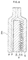
- Fig. 8 is a sectional view showing the layer structure of an occlusion condition detecting sheet used in a second embodiment of the invention.
- the shape and structure in the plan view of the sheet is similar to the sheet shown in Fig. 1.
- the pressure-sensitive composite recording sheet structure 15 contained within the occlusion condition detecting sheet 28A comprises, similar to that used in the first embodiment, a support 10, a color developer layer 12 coated on one face of the support 10 and a microcapsulated color former layer 14, and has a generally horseshoe-like shape to extend along the arcuated dental arch of human being.
- reference numeral 16 designates a first water-impermeable layer or backside Waterproof layer which may be made of a transparent PET film, similar to the film forming the support sheet 10, having a thickness of, for example, 16 ⁇ m.
- a tackifying adhesive is coated on one face, the face opposing to the support sheet 10. of the first water-impermeable layer 16 to form an adhesive layer 18.
- the first water-impermeable layer 16 is liquid-tightly applied on one face (the face opposing to the face to which the color developer layer 12 is applied) of the support sheet 10 through this adhesive layer 18.
- Reference numeral 20 designates a second water-impermeable layer or obverse waterproof layer which may be made of a transparent PET film, similar to the film forming the first water-impermeable layer 16, having a thickness of, for example, 16 ⁇ m.
- This second water-impermeable layer 20 is overlaid on the color former layer 14 and has the peripheral margin sealingly adhering to the adhesive layer 18 applied on the first water-impermeable layer 16. It is desirous that the margnial portions of both water-impermeable layers 16 and 20 are sealed under a sufficiently reduced pressure.
- the generally horseshoe-shaped pressure sensitive composite recording sheet structure 15 is covered with water-impermeable layers 16, 20 with the periphery thereof being sealed through an adhesive layer 18 to the water-impermeable layer 16. Accordingly, the interior of the occlusion condition detecting sheet 28A is liquid-tightly sealed by the first water-impermeable layer 16 and the second water-impermeable layer 20.
- the occlusion condition detecting sheet 28A is improved in waterproof property and exhibits high reliability in use, in that coloring property thereof is not affected even if saliva or other aqueous liquids adhere thereto.
- the layer 16 is prevented from displacement relative to and delamination from the support sheet 10.
- the second water-impermeable layer 20 is also prevented from relative displacement from the support sheet 10, since the marginal or peripheral portions thereof are fixedly adhering to the marginal or peripheral portions of the first water-impermeable layer 16.
- the occlusion condition detecting sheet 28A is inserted into the opened mouth of the patient so that it is engaged evenly with the upper or lower dental arch. As the patient bites the sheet 28A gently, the occlusion pressures between the upper and lower occluding teeth are applied on the pressure-sensitive composite recording sheet structure 15 so that the portions applied with occluding pressures are colored, in red in the illustrated example, to have densities varied in proportion to the applied pressures.
- the occlusion condition detecting sheet 28A including the pressure-sensitive composite sheet structure 15 having portions colored to have color densities in proportion to the applied pressures is pulled out of the patient's mouth, and then subjected to analysis in the system of the invention.
- Fig. 9 is a block diagram showing the structure and operation sequence of the second embodiment of the invention.
- Fig. 10 is a similar block diagram showing the structure and operation sequence of the second embodiment of the invention;
- Fig. 11 is a flow chart showing the operation sequence taking place in the system according to the second embodiment; and
- Figs. 12 to 20 are photographs or printed matters showing the output images fed from the display or printer means.
- reference numeral 30A designates a scanner for reading the colored image on the pressure-sensitive composite recording sheet structure 15 of the occlusion condition detecting sheet 28A from the side of the color former layer 14 (see Fig. 8), and composed of a color scanner in the illustrated embodiment.
- Reference numeral 34A designates a memory which stores the images read by the scanner 30A, the processed images or the data obtained through various processings.
- reference numeral 38A designates a central processing unit (CPU)
- reference numeral 40 designates a keyboard which may be used also as the selector means
- reference numeral 42 designates a cathode ray tube (CRT) which is used as the output means
- reference numeral 44 designates a printer which is also used as the output means.
- These members are mutually connected through a bus 46A.
- the memory 34 and the scanner 30 are also connected to the bus 46A.
- Reference numeral 48 designates an image processor by which the images read by the sanner 30A are processed through spatial filtering to be subjected to contour emphasizing, levelling and/or other necessary processings.
- Reference numeral 50 designates a color density detector for detecting the density of coloring on the pressure-sensitive composite recording sheet structure 15.
- Reference numeral 52 designates an occlusion pressure detecting means for receiving the outputs, i.e. the color densities D, from the color density detecting means 50 to determine the occlusion pressures P while referring to the curve showing the interrelation between P and D.
- Reference numeral 54 designates a graduator, which serves as the graduation display means, for determining the graduations or color ranges for respective occlusion pressure ranges. For example, it is possible to designate specified colors for respective occlusion pressure ranges so that the occluding points, at which the upper and lower teeth occlude at different pressures, are represented by different colors.
- the pressure ranges are specifically identied as follows:
- Reference numeral 56 designates a processor for carrying out a desired operation selected from plural operation programs through the keyboard 40 which serves as the mode selector means.
- the processor 56 is constituted of the CPU 38A in combination with various operation programs, it is denoted in Fig. 10 by plural separate blocks 58 to 70 for respective operation functions in order to facilitate prompt understanding thereof. The contents of these various operations will be described below.
- a processor 58 is provided to find the occlusion pressure distribution and to feed the thus found output to the CRT 42 or the printer 44 which gives the displayed images or a print as shown in Fig. 12 (this processor 58 will be referred to as an abridged notation of "Processor for OPD" in Fig. 10).
- the processor 58 analyzes the detected occlusion pressure distribution to display four separate images selectively in respective quarter parts 7A to 7D, such that the part 7A shows the tooth traces on which occlusion pressures each having a strength of not less than 95% of the maximum occlusion pressure (131 kg/cm 2 in the illustrated example) are applied, the part 7B shows the tooth traces on which occlusion pressures each having not less than 90% of the maximum occlusion pressure are applied, the part 7C shows the tooth traces on which occlusion pressures each having not less than 70% of the maximum occlusion pressure are applied, and the part 7D shows the tooth traces on which occlusion pressures each having not less than 50% of the maximum occlusion pressure are applied.
- the part 7A shows the tooth traces on which occlusion pressures each having a strength of not less than 95% of the maximum occlusion pressure (131 kg/cm 2 in the illustrated example) are applied
- the part 7B shows the tooth traces on which o
- Another processor 60 is provided to find the occlusion pressure balance and to feed the thus found output to the output means 42 or 44 which gives the displayed images or a print as shown in Fig. 13 (this processor 60 will be referred to as an abridged notation of "Processor for OPB" in Fig. 10).
- the processor 60 operates to find the marginal or peripheral distribution of occlusion pressures by displaying a histogram 8A showing the occlusion pressure distribution in the fore and back tooth rows, a histogram 8C showing the occlusion pressure distribution in the right half of the dental arch and a histogram 8D showing the occulusion pressure distribution in the left half of the dental arch, the dental arch being divided into the right and left halves by the splitting center line 8B.
- the positions, respectively showing the centers or geometrical means of the applied occlusion pressures, are shown by 8AA, 8CC and 8DD in Fig. 13.
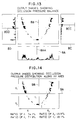
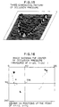
- a further processor 62 is provided to find the occlusion pressure distributions along the X and Y axes to feed the output as shown in Fig. 14 (this processor 62 will be referred to as an abridged notation of "Processor for OPD along XY Axes" in Fig. 10).
- This processor 62 operates to calculate the ratios of the sums of the occlusion pressures within the respective parts X 1 and X 2 , which are divided by the Y axis 9B, relative to the total occlusion pressures; and also operates to calculate the ratios of the sums of the occlusion pressures within the respective parts Y 1 and Y 2 , which are divided by the X axis 9A, relative to the total occlusion pressures, the coordinates axes 9A and 9B being inputted through the keyboard 40.
- a further processor 64 for picturing a three-dimensional pattern of occlusion pressures is provided to output the pattern as shown in Fig. 15 (this processor 64 will be referred to as an abridged notation of "Processor for Picturing 3D Pattern" in Fig. 10).
- This processor 64 operates to express the occlusion pressure distribution in a three-dimensional sierra form to facilitate prompt grasping of the occlusion pressure distribution.
- a further processor 66 for determining the center of occlusion pressures is provided to output the diagram shown in Fig. 16 in which the center 11A of the occulusion pressure distribution is shown in overlapping condition with the image showing the occlusion pressure distribution (this processor 66 will be referred to as an abridged notation of "Processor for Determining OPC" in Fig. 10).
- this processor 66 will be referred to as an abridged notation of "Processor for Determining OPC" in Fig. 10).
- the center 11A stands for the point of geometrical mean or the center of gravity when the pressures applied on respective occluding points are regarded as if they are gravities.
- a still further processor 68 for calculating the mean or average value of the occlusion pressure loading is provided to output the diagram shown in Fig. 17 (this processor 68 will be referred to as an abridged notation of "Processor for Calculating Mean of OPL" in Fig. 10).
- This processor 68 is provided to know the average values of the occlusion pressures (loadings) within respective ranges. For example, an average pressure or loading is calculated by dividing the sum of occlusion pressures applied on the points contained in a pressure range of from 60 to 70 kg/cm 2 by the sum of areas of respective points.
- the points on which occlusion pressures within respective ranges are applied are shown with different colors. The used colors are shown in a series of color scale 12A, 12B, 12C, 12D, 12E and 12F in the Figure.
- a further processor 70 for calculating the area ratio of the occluding points applied with occlusion pressures is provided to output the diagram of Fig. 18 (this processor 70 will be referred to as an abridged notation of "Processor for Calculating AR of OP" in Fig. 10).
- This processor 70 operates to calculate the sum of the areas of the occluding points contained in respective pressure ranges, and then the thus calculated sum is divided by the ratio of the areas relative to the total areas of the entire occluding points.
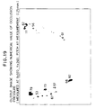
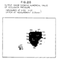
- Desired points to be measured may be designated through the keyboard 40 to instruct the processor 56 to feed outputs for displaying the numerical values of occlusion pressures on respective points, as shown in Figs. 19 and 20.
- Fig. 19 shows the numerical values of the occlusion pressures applied on particular measured points, particular measured points being selectively designated, by the keyboard 40, from the points of the dental arch displayed on the CRT 42 in a manner such that the image of dental arch is displayed with different colors depending on the pressure ranges.
- Fig. 20 shows, in an enlarged scale, the occlusion pressure distribution within a specifically designated area more in detail, the specifically designated area being determined by the instruction through the keyboard 40.
- the occlusion condition detecting sheet 28A which has been bitten by the patient, is set in the system so that the color former layer side faces to the scanner 30A.
- the colored image recorded on the pressure-sensitive composite recording sheet structure 15 is thus read through scanning by the scanner 30A (Step 200; Reading of Occlusion Pressure), and then subjected to a proper image processing to be stored in the memory 34A (Step 202).
- the densities of the colored images are detected by the color density detector 50 (Step 204; Detection of Occlusion Pressure).
- the occlusion pressures D corresponding to respective densities P are determined by the occlusion pressure detector 52 in which reference is made to the curve showing the interrelation between P and D (Step 206; Determination of Occlusion Pressure).
- the thus determined occlusion pressures are converted to colors which is varied, by the graduator 54, correspondingly to the strengths of the applied pressures (Step 208; Conversion to Color Graduation), and then stored in the memory 34A (Step 210).
- Step 212 Mode Selection
- the processor 58 operates to carry out necessary processing (Step 214; calculation of OPD), and the output therefrom is fed to the output means 42 or 44 to give a diagram similar to that shown in Fig. 12 (Step 216; Image Output).
- the corresponding one of the processors 60, 62, 64, 66, 68 or 70 is operated to feed the outputs for displaying one of the images shown in Figs. 13, 14, 15, 16, 17 and 18 (Step 218, 220, 222, 224, 226 or 228).
- any one or more of plural processings can be carried out by the use of the data relating to the occlusion pressures which are determined from the colored images recorded on the pressure-sensitive composite recording sheet structure, the distribution of occlusion pressures and the occluding conditions at respective points can be precisely detected to enable precise diagnosis on the occluding condition thereby to obtain effectual data for the determination of subsequent treating course.
- the patient can have diagnosed with each by biting the occlusion pressure detecting sheet 28A only one time on one hand, and on the other hand the dentist can readily judge the interrelation between the occluded positions and the occlusion pressures only by observing the occlusion pressure detecting sheet 28A without the need of continuous watching of the oral cavity of the patient.
- the dentist can know the occluding condition of teeth by himself or herself.
Landscapes
- Health & Medical Sciences (AREA)
- Life Sciences & Earth Sciences (AREA)
- General Health & Medical Sciences (AREA)
- Oral & Maxillofacial Surgery (AREA)
- Dentistry (AREA)
- Epidemiology (AREA)
- Animal Behavior & Ethology (AREA)
- Public Health (AREA)
- Veterinary Medicine (AREA)
- Biomedical Technology (AREA)
- Biophysics (AREA)
- Engineering & Computer Science (AREA)
- Physics & Mathematics (AREA)
- Optics & Photonics (AREA)
- Dental Tools And Instruments Or Auxiliary Dental Instruments (AREA)
Claims (10)
- Système pour l'analyse de l'état d'occlusion d'un patient en contrôlant une feuille (28) de diagnostic de l'état d'occlusion comprenant une structure (15) de la feuille d'enregistrement composite sensible à la pression et ayant au moins une surface revêtue d'une couche (24, 26) de revêtement de cire,
caractérisé en ce qu'il comprend :(a) un premier scanner (30, 32) pour lire l'image du modèle d'arc dentaire du patient, l'image étant enregistrée sur ladite couche (24, 26) du revêtement de cire ;(b) un second scanner (30, 32) pour lire les densités de couleurs développées sur ladite structure (15) de la feuille d'enregistrement composite sensible à la pression, les densités de couleurs étant proportionnelles aux pressions d'occlusion appliquées par des dents respectives du patient qui prennent une position d'occlusion ;(c) un moyen (52) de détection de la pression d'occlusion pour convertir en pressions les densités de couleurs lues par ledit second scanner (30, 32) ;(d) un moyen (54) de visualisation de la graduation servant à convertir les pressions d'occlusion détectées en graduations de densité pour afficher les graduations de densité ainsi obtenues ; et(e) des moyens de sortie (42, 44) pour fournir soit ladite image de l'arc dentaire du patient ou la répartition desdites graduations de densité des dents respectives prenant une position d'occlusion, soit pour fournir à la fois ladite image et ladite répartition. - Système selon la revendication 1, dans lequel lesdits moyens de sortie comprennent des moyens de visualisation (42, 44) et dans lequel ladite image de l'arc dentaire du patient et la répartition desdites graduations de densité des dents respectives prenant une position d'occlusion sont affichées sur lesdits moyens de visualisation (42, 44) en se chevauchant.
- Système selon la revendication 1, dans lequel un seul scanner (30, 32) est prévu pour servir à la fois de premier (30) et de second (32) scanners, de façon telle que ledit seul scanner peut fonctionner comme dit premier scanner (30) à tout moment souhaité et qu'il peut fonctionner comme dit second scanner (32) à tout moment autre que celui où il est utilisé pour comme dit premier scanner (30).
- Système selon la revendication 1, dans lequel ladite couche (24, 26) du revêtement de cire a une couleur différenciée par rapport à la couleur développée sur ladite structure (15) de la feuille d'enregistrement composite sensible à la pression, et dans lequel ledit premier scanner (30) détecte sélectivement la couleur de ladite couche (24, 26) du revêtement de cire, et dans lequel ledit second scanner (32) détecte sélectivement la couleur développée sur ladite structure (15) de la feuille d'enregistrement composite sensible à la pression.
- Système selon la revendication 1, dans lequel ledit moyen (54) de visualisation de la graduation affiche la modification de la pression d'occlusion en fonction du changement du ton de couleur.
- Système selon la revendication 1, dans lequel ledit moyen de sortie comprend une imprimante (44) qui peut produire une image imprimée.
- Système selon la revendication 1, dans lequel ledit moyen de sortie (42, 44) comprend un moyen de visualisation servant à afficher l'image du modèle d'arc dentaire dans une certaine couleur et à afficher les pressions d'occlusion dans des tons de couleurs différents de ladite certaine couleur utilisée pour afficher ladite image de l'arc dentaire.
- Système pour l'analyse de l'état d'occlusion d'un patient en contrôlant une feuille (28A) de diagnostic de l'état d'occlusion comprenant une structure (15) de la feuille d'enregistrement composite sensible à la pression ayant deux surfaces recouvertes de façon étanche par des couches (16, 20) imperméables à l'eau,
caractérisé par le fait qu'il comprend :(a) un scanner (30A) pour lire la densité de couleur développée sur ladite structure (15) de la feuille d'enregistrement composite sensible à la pression, la densité de couleur étant proportionnelle à la pression d'occlusion appliquée par des dents respectives du patient qui prennent une position d'occlusion ;(b) un détecteur (52) de la pression d'occlusion pour convertir en pressions les densités de couleurs lues par ledit scanner ;(c) un processeur (56) pour traiter les pressions au moyen de plusieurs sortes de traitement ;(d) un moyen (40) formant sélecteur de mode pour sélectionner un traitement particulier à partir de plusieurs sortes de traitement ; et(e) des moyens de sortie (42, 44) pour fournir le résultat du traitement de l'opération effectuée suivant l'instruction fournie par ledit sélecteur de mode. - Système selon la revendication 8 comprenant en outre :dans lequel lesdits moyens de sortie comprennent des moyens de visualisation (42, 44) pour afficher la répartition de ladite graduation de densité des dents respectives prenant une position d'occlusion, ainsi que le résultat du traitement d'opération effectué par ledit processeur (56).(f) un moyen (54) de visualisation de la graduation servant à convertir en graduations de densité les pressions d'occlusion détectées par ledit détecteur de pression d'occlusion pour afficher les graduations de densité ainsi obtenues ; et
- Système selon la revendication 8, dans lequel ledit processeur fonctionne pour trouver la moyenne géométrique des pressions d'occlusion dans l'arc dentaire du patient.
Applications Claiming Priority (4)
| Application Number | Priority Date | Filing Date | Title |
|---|---|---|---|
| JP30297892A JP3150797B2 (ja) | 1992-10-15 | 1992-10-15 | 咬合圧診断装置 |
| JP302978/92 | 1992-10-15 | ||
| JP04302977A JP3077955B2 (ja) | 1992-10-15 | 1992-10-15 | 咬合圧診断装置 |
| JP302977/92 | 1992-10-15 |
Publications (2)
| Publication Number | Publication Date |
|---|---|
| EP0593061A1 EP0593061A1 (fr) | 1994-04-20 |
| EP0593061B1 true EP0593061B1 (fr) | 1998-01-14 |
Family
ID=26563333
Family Applications (1)
| Application Number | Title | Priority Date | Filing Date |
|---|---|---|---|
| EP93116652A Expired - Lifetime EP0593061B1 (fr) | 1992-10-15 | 1993-10-14 | Système pour l'analyse de l'occlusion dentaire |
Country Status (3)
| Country | Link |
|---|---|
| US (1) | US5458487A (fr) |
| EP (1) | EP0593061B1 (fr) |
| DE (1) | DE69316306T2 (fr) |
Families Citing this family (28)
| Publication number | Priority date | Publication date | Assignee | Title |
|---|---|---|---|---|
| JPH09322883A (ja) * | 1996-06-05 | 1997-12-16 | Tadahiko Kawai | 顎関節の接触圧分布状態の解析装置 |
| US5732721A (en) * | 1996-10-21 | 1998-03-31 | Pelok; Brett S. | Dental floss with a pressure sensitive material |
| IL120892A (en) | 1997-05-22 | 2000-08-31 | Cadent Ltd | Method for obtaining a dental occlusion map |
| US6089864A (en) * | 1997-11-14 | 2000-07-18 | William L. Hintermister | Bio-feedback, data acquisition teeth guards, methods of their manufacture and use |
| EP1120081A3 (fr) * | 2000-01-27 | 2002-05-08 | Matsushita Electric Industrial Co., Ltd. | Appareil d'imagerie de la bouche |
| US6582225B1 (en) * | 2000-10-11 | 2003-06-24 | Earl O. Bergersen | Dental diagnosis and dispensing apparatus and a system and a method for providing same |
| US7716024B2 (en) | 2002-04-29 | 2010-05-11 | Geodigm Corporation | Method and apparatus for electronically generating a color dental occlusion map within electronic model images |
| US7108190B2 (en) * | 2003-02-28 | 2006-09-19 | Appleton Papers Inc. | Token array and method employing authentication tokens bearing scent formulation information |
| DE10317245B3 (de) * | 2003-04-10 | 2004-09-23 | Müller, Wolf-Dieter, Prof. Dr.rer.nat. | Messungs-Set für die Okklusions-, Kaukraft- und Kaudruckbestimmung und Meßverfahren |
| US20060063125A1 (en) * | 2003-04-22 | 2006-03-23 | Hamilton Timothy F | Method and device for enhanced dental articulation |
| US6932602B2 (en) * | 2003-04-22 | 2005-08-23 | Appleton Papers Inc. | Dental articulation kit and method |
| US20040251309A1 (en) * | 2003-06-10 | 2004-12-16 | Appleton Papers Inc. | Token bearing magnetc image information in registration with visible image information |
| US7702492B2 (en) | 2004-03-11 | 2010-04-20 | Geodigm Corporation | System and method for generating an electronic model for a dental impression having a common coordinate system |
| US7824346B2 (en) * | 2004-03-11 | 2010-11-02 | Geodigm Corporation | Determining condyle displacement utilizing electronic models of dental impressions having a common coordinate system |
| EP1607041B1 (fr) | 2004-06-17 | 2008-01-16 | Cadent Ltd. | Méthode pour fournir des données concernant la cavité intra-orale |
| US20060141416A1 (en) * | 2004-12-24 | 2006-06-29 | Knutson Eric J | Occlusal indicator tray & processes therefor |
| TW200808273A (en) * | 2006-08-03 | 2008-02-16 | Univ Kaohsiung Medical | Dual-end test stick and occlusion test device with the dual-end test stick |
| US9022961B2 (en) | 2009-07-30 | 2015-05-05 | Mcneil-Ppc., Inc. | Oral care cleaning and treating device |
| US9022960B2 (en) | 2009-07-30 | 2015-05-05 | Mcneil-Ppc, Inc. | Oral care cleaning and treating device |
| US8617090B2 (en) * | 2009-07-30 | 2013-12-31 | Mcneil-Ppc, Inc. | Oral care device |
| DE102009044826A1 (de) * | 2009-12-09 | 2011-06-22 | Heinrich-Heine-Universität, 40225 | Thermoplastisch verformbare Folie zur Herstellung einer Aufbißschiene für zahnärztliche Untersuchungen, Aufbißschiene für zahnärztliche Untersuchungen, Verfahren und Anordnung zum Ermitteln von für zahnärztliche Untersuchungen relevanten Parametern unter Verwendung von Aufbißschienen sowie Verwendung eines speziellen Copolymers zur Herstellung einer thermoplastisch verformbaren Folie für eine Aufbißschiene |
| DE102010023406A1 (de) * | 2010-06-11 | 2011-12-15 | Kevin Hintersehr | Verfahren und Datenverarbeitungsvorrichtung zum Bereitstellen von Geometriedaten von Zahn-und/oder Kieferbereichen |
| US9308064B2 (en) * | 2010-07-26 | 2016-04-12 | Johnson & Johnson Consumer Inc. | Devices and methods for collecting and analyzing fluid samples from the oral cavity |
| US9226806B2 (en) | 2010-09-17 | 2016-01-05 | Biocad Medical, Inc. | Occlusion estimation in dental prosthesis design |
| US9675305B2 (en) | 2014-06-03 | 2017-06-13 | Ortho-Tain | System and method for determining an orthodontic diagnostic analysis of a patient |
| CA3075728C (fr) * | 2017-09-14 | 2022-09-06 | Gc Corporation | Dispositif d'analyse de la pression occlusale, programme d'analyse de la pression occlusale, et procede d'analyse de la pression occlusale |
| US11622751B2 (en) | 2018-12-19 | 2023-04-11 | Johnson & Johnson Consumer Inc. | Devices and methods for collecting saliva samples from the oral cavity |
| WO2023055293A2 (fr) * | 2021-09-29 | 2023-04-06 | National University Of Singapore | Système de protège-dents pour interaction homme-machine |
Family Cites Families (12)
| Publication number | Priority date | Publication date | Assignee | Title |
|---|---|---|---|---|
| US3349489A (en) * | 1963-02-07 | 1967-10-31 | Shackelford John Hinton | Multiple celled pressure sensitive dental device for measuring relative occlusal pressures |
| US3959881A (en) * | 1975-04-25 | 1976-06-01 | Kokal Jr August | Bite intensity detecting articulating paper |
| JPS56142430A (en) * | 1980-03-24 | 1981-11-06 | Morita Mfg Co Ltd | Biting pressure sensor |
| JPS5848175B2 (ja) * | 1980-05-02 | 1983-10-27 | 株式会社 モリタ製作所 | 全顎の咬合圧画像表示装置 |
| US4521186A (en) * | 1983-05-17 | 1985-06-04 | Harold Wodlinger | System for determining the first prematurity contact of dental occlusion |
| US4547155A (en) * | 1984-03-15 | 1985-10-15 | Adler Harold A | Shielded dental contact marker |
| US4592727A (en) * | 1984-05-24 | 1986-06-03 | Pennwalt Corporation | Piezoelectric polymeric film discriminating bite force occlusal indicator |
| US4734034A (en) * | 1985-03-29 | 1988-03-29 | Sentek, Incorporated | Contact sensor for measuring dental occlusion |
| US4676748A (en) * | 1986-07-07 | 1987-06-30 | Walter A. Hackler | Occlusal impression device |
| JPS6437949A (en) * | 1987-07-31 | 1989-02-08 | Wada Seimitsu Shiken | Dental occlusion recording member |
| DE3932151A1 (de) * | 1989-09-22 | 1991-04-04 | Peter Rohleder | Vorrichtung zur scannenden erfassung eines innenraums |
| JPH0499569A (ja) * | 1990-03-10 | 1992-03-31 | Kazuo Eto | 接触体形状と接触状態の同時測定体 |
-
1993
- 1993-10-14 EP EP93116652A patent/EP0593061B1/fr not_active Expired - Lifetime
- 1993-10-14 DE DE69316306T patent/DE69316306T2/de not_active Expired - Lifetime
- 1993-10-15 US US08/136,133 patent/US5458487A/en not_active Expired - Lifetime
Also Published As
| Publication number | Publication date |
|---|---|
| DE69316306T2 (de) | 1998-04-23 |
| US5458487A (en) | 1995-10-17 |
| EP0593061A1 (fr) | 1994-04-20 |
| DE69316306D1 (de) | 1998-02-19 |
Similar Documents
| Publication | Publication Date | Title |
|---|---|---|
| EP0593061B1 (fr) | Système pour l'analyse de l'occlusion dentaire | |
| US5395239A (en) | Occlusion pressure detecting sheet | |
| JPH0526143B2 (fr) | ||
| CA1323207C (fr) | Methode d'identification et d'analyse d'illustrations imprimees, au moyen d'un densimetre, et appareil connexe | |
| JP3328015B2 (ja) | ニューラルネットワークを用いた粒子凝集パターンの判定方法 | |
| JP3522851B2 (ja) | 検出方法 | |
| US8611619B2 (en) | Read-out method and apparatus | |
| JP3077955B2 (ja) | 咬合圧診断装置 | |
| JPS6128089B2 (fr) | ||
| JP3604316B2 (ja) | 発色画像測定セット、発色画像測定用シート容器の固定治具及び発色画像測定方法 | |
| JPH10274653A (ja) | イムノクロマトグラフィによる検体の画像処理定量方 法 | |
| JP3150797B2 (ja) | 咬合圧診断装置 | |
| JPH1073534A (ja) | 呈色物定量装置 | |
| JPH0754275B2 (ja) | 圧力分布測定装置 | |
| JP2000338106A (ja) | 免疫反応による発色画像の処理定量方法 | |
| Liebson et al. | Hypertension research. Echocardiography in the measurement of left ventricular wall mass. | |
| JPH0755570A (ja) | 標本の色彩と光沢度から再現データまたは評価のデータを取得する装置 | |
| JPH05192359A (ja) | 歯列噛み合わせ検査具 | |
| JP2901642B2 (ja) | 画像自動判定による抗原又は抗体の反応の有無の判定方法及び画像自動判定装置 | |
| JP2587824B2 (ja) | 細胞分析装置 | |
| CN116473711A (zh) | 一种定向测量牙齿咬合接触稳定性的咬合指示装置及其使用方法 | |
| JP2511347Y2 (ja) | 咬合診査装置 | |
| JPH07104122B2 (ja) | 感圧紙を用いた隙間測定法 | |
| Wald et al. | Alpha fetoprotein screening and diagnosis of fetal open neural tube defects: The need for quality control | |
| JPS63259442A (ja) | 細胞分析装置 |
Legal Events
| Date | Code | Title | Description |
|---|---|---|---|
| PUAI | Public reference made under article 153(3) epc to a published international application that has entered the european phase |
Free format text: ORIGINAL CODE: 0009012 |
|
| AK | Designated contracting states |
Kind code of ref document: A1 Designated state(s): DE FR GB |
|
| 17P | Request for examination filed |
Effective date: 19941020 |
|
| 17Q | First examination report despatched |
Effective date: 19961007 |
|
| GRAG | Despatch of communication of intention to grant |
Free format text: ORIGINAL CODE: EPIDOS AGRA |
|
| GRAG | Despatch of communication of intention to grant |
Free format text: ORIGINAL CODE: EPIDOS AGRA |
|
| GRAH | Despatch of communication of intention to grant a patent |
Free format text: ORIGINAL CODE: EPIDOS IGRA |
|
| GRAH | Despatch of communication of intention to grant a patent |
Free format text: ORIGINAL CODE: EPIDOS IGRA |
|
| GRAA | (expected) grant |
Free format text: ORIGINAL CODE: 0009210 |
|
| AK | Designated contracting states |
Kind code of ref document: B1 Designated state(s): DE FR GB |
|
| REF | Corresponds to: |
Ref document number: 69316306 Country of ref document: DE Date of ref document: 19980219 |
|
| ET | Fr: translation filed | ||
| PLBE | No opposition filed within time limit |
Free format text: ORIGINAL CODE: 0009261 |
|
| STAA | Information on the status of an ep patent application or granted ep patent |
Free format text: STATUS: NO OPPOSITION FILED WITHIN TIME LIMIT |
|
| 26N | No opposition filed | ||
| REG | Reference to a national code |
Ref country code: GB Ref legal event code: IF02 |
|
| REG | Reference to a national code |
Ref country code: GB Ref legal event code: 732E |
|
| REG | Reference to a national code |
Ref country code: FR Ref legal event code: TP Ref country code: FR Ref legal event code: CD |
|
| PGFP | Annual fee paid to national office [announced via postgrant information from national office to epo] |
Ref country code: FR Payment date: 20081014 Year of fee payment: 16 |
|
| PGFP | Annual fee paid to national office [announced via postgrant information from national office to epo] |
Ref country code: GB Payment date: 20081008 Year of fee payment: 16 |
|
| REG | Reference to a national code |
Ref country code: FR Ref legal event code: ST Effective date: 20100630 |
|
| PG25 | Lapsed in a contracting state [announced via postgrant information from national office to epo] |
Ref country code: FR Free format text: LAPSE BECAUSE OF NON-PAYMENT OF DUE FEES Effective date: 20091102 |
|
| PG25 | Lapsed in a contracting state [announced via postgrant information from national office to epo] |
Ref country code: GB Free format text: LAPSE BECAUSE OF NON-PAYMENT OF DUE FEES Effective date: 20091014 |
|
| PGFP | Annual fee paid to national office [announced via postgrant information from national office to epo] |
Ref country code: DE Payment date: 20121010 Year of fee payment: 20 |
|
| REG | Reference to a national code |
Ref country code: DE Ref legal event code: R071 Ref document number: 69316306 Country of ref document: DE |
|
| PG25 | Lapsed in a contracting state [announced via postgrant information from national office to epo] |
Ref country code: DE Free format text: LAPSE BECAUSE OF EXPIRATION OF PROTECTION Effective date: 20131015 |