EP0590690B2 - Saugdüse - Google Patents
Saugdüse Download PDFInfo
- Publication number
- EP0590690B2 EP0590690B2 EP93116250A EP93116250A EP0590690B2 EP 0590690 B2 EP0590690 B2 EP 0590690B2 EP 93116250 A EP93116250 A EP 93116250A EP 93116250 A EP93116250 A EP 93116250A EP 0590690 B2 EP0590690 B2 EP 0590690B2
- Authority
- EP
- European Patent Office
- Prior art keywords
- suction nozzle
- main body
- suction
- nozzle main
- flexible member
- Prior art date
- Legal status (The legal status is an assumption and is not a legal conclusion. Google has not performed a legal analysis and makes no representation as to the accuracy of the status listed.)
- Expired - Lifetime
Links
- 230000008878 coupling Effects 0.000 claims description 36
- 238000010168 coupling process Methods 0.000 claims description 36
- 238000005859 coupling reaction Methods 0.000 claims description 36
- 238000009429 electrical wiring Methods 0.000 claims description 6
- 238000004140 cleaning Methods 0.000 description 22
- 239000000428 dust Substances 0.000 description 9
- 239000007787 solid Substances 0.000 description 6
- 238000005452 bending Methods 0.000 description 3
- 238000010586 diagram Methods 0.000 description 3
- 239000000463 material Substances 0.000 description 3
- 229920003002 synthetic resin Polymers 0.000 description 3
- 239000000057 synthetic resin Substances 0.000 description 3
- 235000017060 Arachis glabrata Nutrition 0.000 description 2
- 244000105624 Arachis hypogaea Species 0.000 description 2
- 235000010777 Arachis hypogaea Nutrition 0.000 description 2
- 235000018262 Arachis monticola Nutrition 0.000 description 2
- 230000003247 decreasing effect Effects 0.000 description 2
- 235000020232 peanut Nutrition 0.000 description 2
- JOYRKODLDBILNP-UHFFFAOYSA-N Ethyl urethane Chemical compound CCOC(N)=O JOYRKODLDBILNP-UHFFFAOYSA-N 0.000 description 1
- 240000007594 Oryza sativa Species 0.000 description 1
- 235000007164 Oryza sativa Nutrition 0.000 description 1
- 230000002159 abnormal effect Effects 0.000 description 1
- 238000010009 beating Methods 0.000 description 1
- 230000000903 blocking effect Effects 0.000 description 1
- 235000009508 confectionery Nutrition 0.000 description 1
- 230000007547 defect Effects 0.000 description 1
- 230000000694 effects Effects 0.000 description 1
- 239000013013 elastic material Substances 0.000 description 1
- 230000005611 electricity Effects 0.000 description 1
- 239000006261 foam material Substances 0.000 description 1
- 230000001771 impaired effect Effects 0.000 description 1
- 239000012212 insulator Substances 0.000 description 1
- 239000008188 pellet Substances 0.000 description 1
- 230000002093 peripheral effect Effects 0.000 description 1
- 235000009566 rice Nutrition 0.000 description 1
- 230000003068 static effect Effects 0.000 description 1
- 239000000758 substrate Substances 0.000 description 1
- 238000010408 sweeping Methods 0.000 description 1
Images


Classifications
-
- A—HUMAN NECESSITIES
- A47—FURNITURE; DOMESTIC ARTICLES OR APPLIANCES; COFFEE MILLS; SPICE MILLS; SUCTION CLEANERS IN GENERAL
- A47L—DOMESTIC WASHING OR CLEANING; SUCTION CLEANERS IN GENERAL
- A47L9/00—Details or accessories of suction cleaners, e.g. mechanical means for controlling the suction or for effecting pulsating action; Storing devices specially adapted to suction cleaners or parts thereof; Carrying-vehicles specially adapted for suction cleaners
- A47L9/02—Nozzles
- A47L9/04—Nozzles with driven brushes or agitators
- A47L9/0405—Driving means for the brushes or agitators
- A47L9/0411—Driving means for the brushes or agitators driven by electric motor
Definitions
- the present invention relates to a suction nozzle of a vacuum cleaner according to the preamble of claim 1.
- a suction nozzle is known from GB 2 002 864. More particularly, it relates to a suction nozzle where an electrical wiring is provided to guide electricity from a vacuum cleaner main body towards the nozzle.
- GB 2 002 864 discloses an electrically-powered intake head for floor-care devices.
- the intake head is connectable to a suction hose via two parts that allow rotation of the head around a horizontal axis and around a more or less vertical axis.
- the electrical wiring comes from the inside of the intake head, and thus into the first part, is there led to the outside of the first part and enters to the inside of the second part.
- the portion at the first part, where the electrical wiring is guided on the outside is covered by a cover.
- a thin plate shape flexible member is provided on the vicinity of a front edge of a suction opening formed in a suction nozzle main body as shown in, for example Japanese Patent Laid-Open No. 120824/1980.
- This flexible member of the suction nozzle main body is projected below a bottom face of the suction nozzle main body and closes a small clearance, which is formed between the floor surface and the suction nozzle main body by the provision of the wheels attached at the bottom face of the suction nozzle main body.
- the flexible member is bent toward an inner portion of the suction nozzle main body when the suction force works and makes a small clearance between a lower end of the flexible member and the floor surface, when the small clearance is made smaller the suction force into the suction nozzle main body is made weaker.
- the friction resistance is made large between the flexible member and the carpet. Further, since the air flow flowing into the suction opening of the suction nozzle main body is made less and the negative pressure in the suction opening is made large, therefore the operability of the suction nozzle is impaired because a compulsive force is required to move the suction nozzle main body.
- a suction nozzle for a vacuum cleaner comprises a suction nozzle main body being formed with a long sideways suction opening which opens toward a floor surface, and a rotary brush provided in the suction nozzle main body and rotating facing to the suction opening of the suction nozzle main body.
- a protection cover is provided on an outside of a bent coupling turning portion which connects the nozzle to the hose of the vacuum cleaner.
- An electric power supply wiring is disposed slackly below the protection cover, so that the power source line can move freely with respect to the move of the bent coupling turning portion.
- the rotary brush rotates and the suction air flow into the suction opening provided in the suction nozzle main body is generated.
- the cleaning surface is beaten by the rotary brush and by the suction air flow, so that dust, which lies on the cleaning surface, is collected into the dust case of the vacuum cleaner main body through the communicating passage, the bent coupling, the extension pipe and the hose.
- the electric power supply wiring for supplying the electric power, which is wired at the bent coupling turning portion, is constituted so as to maintain the space which is formed between the bent coupling turning portion and the protection cover, and the space includes no rib or boss and has a predetermined width.
- the wiring passage for leading from the casing to the suction nozzle main body is made larger than the turning range thereof so as to move freely with no restriction of the move of the electric power supply wiring.
- suction nozzle can move smoothly the large size solid dust being at the corner position into the suction opening of the suction nozzle main body by strong suction force.
- a suction nozzle main body 1 of a suction nozzle with a rotary brush for a vacuum cleaner an electric motor 2 and a rotary brush 3 are provided at an internal portion thereof.
- a long sideways suction opening 4 is formed at a bottom face of the suction nozzle main body 1.
- the long sideways suction opening 4 opens toward a subjective cleaning surface such as a carpet surface, a tatami mat surface and a floor surface etc.
- a bent coupling 6 is provided so as to allow turns in back and forth directions or in right and left directions.
- a communicating passage 5 for communicating between the suction opening 4 and the bent coupling 6 is formed at the internal portion of the suction nozzle main body 1.
- two large size wheels 7 and 8 are provided at the rear portion thereof, and further two small size wheels 9 and 10 are provided at the front portion thereof, respectively.
- side thin plate shape front side flexible member 11 and a rear side thin plate shape flexible member 12 are arranged respectively at the front side and the rear side of the suction opening 4 and extended over the whole lateral width of the suction opening 4 at the horizontal direction.
- a lower face of the front wall of the suction nozzle main body 1 is formed to recede beyond the bottom portion of the suction nozzle main body 1 and thus the front side flexible member 11 is mounted detachably at such recess position 63.
- the suction nozzle main body 1 comprises an upper case 13 made of synthetic resins material which constitutes an upper surface, a suction port cover 14 made of synthetic resins material, and a lower case 15 made of synthetic resins material which constitutes a bottom surface.
- the lower case 15 is fitted to the upper case 13 by screws 16.
- the suction port cover 14 is attached detachably with the upper case 13 and the lower case 15.
- Interior components comprise the electric motor 2, the rotary brush 3, a nozzle piece 17 provided in the communicating passage 5, and a casing 18 which supports rotatively the bent coupling 6 at the back and forth directions, each of the components is installed in the suction nozzle main body 1, respectively.
- the interior components are sandwiched and fixed between the upper case 13 and the lower case 15.
- the bent coupling 6 is supported rotatively with the casing 18 at the right and left directions, and the casing 18 is supported rotatively by the suction nozzle main body 1 at the back and forth directions. Accordingly, the bent coupling 6 can turn with the suction nozzle main body 1 at the back and forth directions and also at the right and left directions.
- the electric motor 2 is supported in the suction nozzle main body 1 vibrationally insulated by two rubber cushion insulator members 20 and 21.
- a first pulley 24 having a first flange portion 23, a bearing 25, and a bearing cover 26 for receiving the bearing 25 with the lower case 15 are provided at the end portion of a rotative shaft 22 of the electric motor 2.
- a second pulley 27 having a second flange portion 28 is provided at the end portion of the rotary brush 3.
- the first pulley 27 and the second pulley 27 have same tooth forms and, however, are made to have different tooth numbers.
- the first flange portion 23 of the first pulley 24 is positioned at the side wall portion side of the suction nozzle main body 1.
- the second flange portion 28 of the second pulley 27 is positioned at the suction opening 4 side of the suction nozzle main body 1, which is in the opposite side of the first flange portion 23.
- Bearings 29 and 30 for the rotary brush 3 are mounted to both end portions of the rotary brush 3.
- a projection member 31 of the rotary brush bearing 29 is put into with a bent portion of the second pulley 27 and the projection member 31 and a projection member 32 are put into the normal position after the press fitting.
- the rotary brush bearing 29 is supported by the inner side wall portion of the suction nozzle main body 1. Accordingly the rotary brush 3 is supported rotatively with the suction nozzle main body 1.
- a timing belt 64 is put up between the first pulley 24 and the second pulley 27, so that the driving power of the electric motor 2 is transmitted to the rotary brush 2.
- the rotary brush 3 is made of urethane foam material and provides a plurality of spirally formed brushes 33 and a spirally projected beating projection member 34.
- Two clamps 35 are mounted on at both end portions of the suction port cover 14 of the rotary brush 3, and the rotary brush 3 is formed so as to be taken out together with the rotary brush bearings 29 and 30 subsequent to the removal of the suction port cover 14.
- the clamp 35 comprises a clamp portion 37 and a projection slip member 39.
- the damp portion 37 fits with a projection member 36 and is disposed detachably so as to fix or remove the projection member 36.
- the projection member 36 is provided on the upper case 13 which is fixed to the suction nozzle main body 1.
- the projection slip member 39 is hooked and fixed with a fixing recess portion 37 which is provided on the lower case 15.
- the suction port cover 14 is disposed detachably by the clamp 35.
- a bearing presser bar spring 40 is provided on the suction port cover 14 at the upper portions of the rotary brush bearings 29 and 30.
- the front side flexible member 11 and a suction guide wall 42 are provided as shown in Fig. 6.
- the front side flexible member 11 has a plurality of indented and notched opening grooves or slits 41.
- the suction guide wall 42 is curved and leaned toward the suction opening 4 side in the suction nozzle main body 1.
- the length of the front side flexible member 11 is set at the lower side longer than the lower end of the suction guide wall 42.
- an end portion 19a of the bumper 19 is provided with a contact state.
- the rear side flexible member 12 is provided in parallel with a lateral width direction of the suction opening 4. The height of the rear side flexible member 12 is set shorter than that of the front side flexible member 11.
- the suction opening 4 of the suction nozzle main body 1 communicates with the casing 18 and the bent coupling 6 through the communicating passage 5 in the suction nozzle main body 1.
- the casing 18 is supported rotatively with the rotative shaft 43, and the casing 18 and the bent coupling 6 are constituted rotatively at the right and left directions, respectively.
- Connecting pins 47 are provided on the bent coupling 6.
- the connecting pins 47 are connected so as to supply the electric power from the vacuum cleaner main body 44 side to the electric motor 2 side through a hose 45 and an extension pipe 46.
- Lead wires 48 are wired from the connecting pins 47.
- a first protection cover 49 and a second protection cover 50 for protecting the lead wires 48 are provided respectively with the covering and enveloping state for the bent coupling 6.
- a space is formed between the first protection cover 49 and the bent coupling 6, thereby the lead wires 48 can move freely according to the movement of the bent coupling 6.
- the first protection cover 49 and the second protection cover 50 are constituted as follows. A part of the second protection cover 50 is fixed to the bent coupling 6 by screws 51.
- the second protection cover 50 has a tube shape body 52 and is connected with the casing 18 side. The second protection cover 50 is overlapped toward the casing 18 side by a faucet joint member 53. After the first protection cover 49 has been fixed to the tube shape body 52, the first protection cover 59 is fixed also to the bent coupling 6 by screws 54.
- the lead wires 48 supply the electric power according to the wirings of an electric circuit diagram shown in Fig. 7.
- Three LED (light emitting diode) lamps 56, 57 and 58 disposed on a substrate plate 55, which is arranged in the electric wirings, are arranged to be switched off when the rotary brush 3 stops, and to be switched on one by one by a switch 59 disposed at the tip of the hose 45 in accordance with the rotation of the rotary brush 3.
- the on- or off-state of the three LED lamps 56, 57 and 58 can be confirmed through a display portion 60 provided on the upper case 13.
- each of the components is connected as shown in Fig. 5 and then the switch 59 disposed at the tip of the hose 45 is turned at the on condition toward a terminal C 1 side. Then an electric blower 61 of the vacuum cleaner main body 44 side and the electric motor 2 of the suction nozzle main body 1 side start to the operation and the LED lamp 56 (green) of the display portion 60 is switched on. With this condition, since the rotary brush 3 rotates at a low speed, the cleaning operation is suitable for the thin carpet and the tatami mat etc.
- the switch 59 when the switch 59 is turned on by switching to a terminal C 2 side, the electric motor 2 in the suction nozzle main body 1 rotates at a high speed, and also the rotary brush 3 can rotate at a high speed similarly.
- the two LED lamps 56 (green) and 57 (green) are switched on. With this condition, the cleaning operation is suitable for the thick carpet.
- the LED lamp 58 (red) includes a positive characteristic thermistor 62 as shown in an electric circuit diagram of Fig. 7.
- the thermistor 62 of the LED lamp 58 (red) presents the exothermic condition and increases the resistance value thereof.
- the current electric current direction of the thermistor 62 of the LED lamp 58 (red) is changed to a direction marked by an arrow R as shown in Fig. 7.
- the LED lamp 56 (red) is switched on and the operator can notice such an abnormal condition.
- the LED lamp 56 (red) is switched on, then the LED lamps 56 (green) and 57 (green) are switched off.
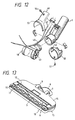
- the front side flexible member 11 and the rear side flexible member 12 have lengths for contacting to the subjective cleaning surface with the front side flexible member 11 and the rear side flexible member 12 as shown in Fig. 1.
- the front side flexible member 11 and the rear side flexible member 12 are bent respectively by the surface air flow being generated by the vacuum cleaner main body 44 as shown in Fig. 3.
- a clearance A between the front side flexible member 11 or the rear side flexible member 12 and the subjective cleaning surface due to this bending varies according to the air quantity in the vacuum cleaner main body 44.
- the clearance A becomes large.
- the air quantity in the vacuum cleaner main body 11 is small due to the blocking by the filter member in the vacuum cleaner main body 44, the clearance A becomes small.
- the air flow velocity flowing into the suction opening 4 of the suction nozzle main body 1 is made constant by the change of the clearance A.
- the set sizes of a plurality of the opening grooves 41 formed on the front side flexible member 11 are as follows.
- the pressure distribution is made on average and high throughout the overall lateral width of the suction nozzle as shown in the curve line Q in Fig. 10.
- the height of the front side flexible member 11 is made constant but the widths W 1 , W 2 , W 3 thereof are set to decrease proportionally toward both end portions of the front side flexible member 11 as shown in Fig. 8.
- the width W of the front side flexible member 11 is made at constant but the heights H 1 , H 2 , H 3 thereof are set to decrease proportionally toward both end portions of the front side flexible member 11 as shown in Fig. 9.
- the strong suction force can be generated at the lengthwise direction all over the suction opening 4 of the suction nozzle main body 1.
- the front side flexible member 11 contacts with the down of the carpet, since the front side flexible member 11 is constituted to lengthen, it is possible to perform easily and smoothly the operation of the suction nozzle main body 1 because the resistance receiving from the carpet is made small.
- the suction guide wall 42 which is disposed between the front side flexible member 11 and the suction opening 4, is arranged slanting toward the inside portion of the suction nozzle main body 1.
- the suction guide wall 42 does not block the move of the bending of the front side flexible member 11.
- the front side flexible member 11 prevents the rotary brush 3 from contacting, due to contact the threshold and push into the front side flexible member 11 toward the inside portion thereof, by the provision of the suction guide wall 42.
- the carpet having long down such as a shaggy type carpet is prevented from twining around the rotary brush 3 by the provision of the suction guide wall 42.
- the bumper 19 provided on the front surface of the suction nozzle main body 1 collides with the wall or the furniture in the room, the bumper 19 deforms through pushing by the wall or the furniture. A lower end portion 62 of the bumper 19 and the root portion of the front side flexible member 11 are pushed respectively toward the inside thereof.
- the clearance A between the front side flexible member 11 and the subjective cleaning surface is made large irrespective of the suction air amount, the large size solid dust such as a peanut is not left behind at the corner portion in the room and is sucked smoothly into the suction opening 4 of the suction nozzle main body 1.
- the front side flexible member 11 is provided on the axis line of the small wheels 9 and 10, so that even when there are up and down portions on the subjective cleaning surface, the clearance A between the front side flexible member 11 and the subjective cleaning surface can be maintained constant.
- the tip of the front side flexible member 11 covers a part of the suction opening 4. Therefore, the opening area of the suction opening 4 is made small and since the suction force is increased, the large size solid dust can be sucked more smoothly into the suction opening 4 of the suction nozzle main body 1.
- the front side flexible member 11 When the front side flexible member 11 is worn out, since the front side flexible member 11 is made separately from the bumper 19 and mounted detachably at the recess portion 63 of the front wall of the suction nozzle main body 1, the front side flexible member 11 can be changed easily independently from the bumper 19.
- the curve rate for deforming of the front side flexible member 11 comprising an elastic material can be made small.
- the life of the front side flexible member 11 can be lengthened by avoiding the compulsory force at its root portion on bending. Further, the force for operating the suction nozzle main body 1 in the back and forth direction can be decreased.
- the suction guide wall 42 disposed at the rear side (suction port side) of the front side flexible member 11 is inclined towards the suction opening 4 side. Therefore, even when the front side flexible member 11 collides with the projection portion (the edge portion of the carpet, the step of the threshold etc.) generated at the subjective cleaning surface and is bent inside thereof by pushing, the front side flexible member 11 can be prevented from colliding with the rotary brush 3. Even when the front side flexible member 11 receives a compulsory force, the suction guide wall 42 works as a wall for receiving the compulsory force, thereby the front side flexible member 11 can be prevented from tearing or being injured.
- the suction guide wall 42 can prevent the long down from clinging to the rotary brush 3 by pushing out the long down of the shaggy carpet. Even when the carpet having the long down is used, the variation of rotation number of the rotary brush 3 can be decreased.
- the rotation number of the rotary brush 3 can be selected high or low according to conditions of use. Even on the tatami mat, the cleaning is carried out at a low rotation number of the rotary brush 3. Therefore, the cleaning of the tatami mat can be carried out maintaining the sweeping effect and the tatami mat is not injured.
- the operator can notice immediately the operating states, in which the floor is injured in the floor cleaning by the rotation of the rotary brush 3, or the rotary brush 3 catches foreign matters and becomes blocked.
- the rotary brush 3 can always be used in the normal rotation condition.
- the rotary brush bearings 29 and 30 of the rotary brush 3 are held at the set pressure force with a predetermined constant direction. Even when an unbalance is generated in the rotary brush 3, the vibration noise in the rotary brush 3 caused by the above unbalance can be restrained.
- the timing belt 64 is not hooked by the second flange portion 28 and can be detached smoothly when servicing the suction nozzle main body 1.
- the power source line which projects from the bent coupling 6 toward the outside portion is enclosed therein, the power source line does not hang to the lower portion of the disk or the leg of the furniture. Therefore, it is possible to clean the cleaning surface in a low and narrow place and the safety for the power surface line can be increased without exerting a compulsive outside force at the root portion of the power source line.
- the bent coupling 6 turning portion of the suction nozzle main body 1 in the present invention is formed with the following structure.
- the shapes of the protection covers constituting the outside shell for the bent coupling 6 are formed to be engaged with the cylinder faucet portion 53 at the casing 18 side and are put the upper and lower fitting structure together at the bent coupling 6 side. Even when a large outside force is exerted at the bent coupling 6 turning portion, the engagement portion thereof does not open, and further the fitting portion thereof does not slip out of place.
- the internal lead wires 48 are arranged with a free shape and with no compulsive force at the space which is formed between the first protection cover 49 and the bent coupling 6, the internal lead wires 48 can move freely when movements in the upper and lower directions and the right and left directions act on them, so that the folding life of the internal lead wires 48 can be improved widely.
Landscapes
- Engineering & Computer Science (AREA)
- Mechanical Engineering (AREA)
- Nozzles For Electric Vacuum Cleaners (AREA)
Claims (1)
- Saugdüse für einen Staubsauger, mitdadurch gekennzeichnet, daßeinem Saugdüsenhauptkörper (1) mit einer langen, querverlaufenden Saugöffnung (4), die sich zu einer Bodenoberfläche öffnet,einer elektrischen Verdrahtung (48),einem an einem mittleren Abschnitt eines hinteren Abschnitts des Saugdüsenhauptkörpers (1) vorgesehenen Gehäuse (18), das nach oben und unten drehbar mit dem Hauptkörper (1) verbunden ist und in dem ein Saugkanal ausgebildet ist,einer gekrümmten, drehbaren Koppeleinrichtung (6), die nach rechts und links drehbar mit dem Gehäuse (18) verbunden ist, undeiner Schutzabdeckung (49, 50, d) einen Freiraum zum Führen der Verdrahtung definiert,die Saugdüse eine rotierende Bürste (3) aufweist, die der Saugdüsenöffnung (4) zugewandt drehbar angeordnet ist,die Saugdüse einen Elektromotor (2) zum Antreiben der rotierenden Bürste (3) aufweist, wobei den Motoren über die elektrische Verdrahtung (48) Energie zugeführt wird,die Verdrahtung außerhalb der gekrümmten Koppeleinrichtung (6) angeordnet ist, unddie Abdeckung (49, 50) außerhalb der gekrümmten Koppeleinrichtung (6) angeordnet und davon abnehmbar ist, um den Freiraum zu definieren, wobei der Freiraum zwischen der Außenseite der gekrümmten Koppeleinrichtung und der Abdeckung (49, 50) Überlängen der elektrischen Verdrahtung (48) aufnimmt.
Applications Claiming Priority (7)
| Application Number | Priority Date | Filing Date | Title |
|---|---|---|---|
| JP63095578A JPH01268526A (ja) | 1988-04-20 | 1988-04-20 | 電気掃除機の回転ブラシ吸口 |
| JP63097792A JP2514688B2 (ja) | 1988-04-20 | 1988-04-20 | 電気掃除機 |
| JP95578/88 | 1988-04-20 | ||
| JP9557888 | 1988-04-20 | ||
| JP9779288 | 1988-04-20 | ||
| JP97792/88 | 1988-04-20 | ||
| EP89106940A EP0338513B1 (de) | 1988-04-20 | 1989-04-18 | Saugmundstück mit einer rotierenden Bürste für Staubsauger |
Related Parent Applications (2)
| Application Number | Title | Priority Date | Filing Date |
|---|---|---|---|
| EP89106940A Division EP0338513B1 (de) | 1988-04-20 | 1989-04-18 | Saugmundstück mit einer rotierenden Bürste für Staubsauger |
| EP89106940.3 Division | 1989-04-18 |
Publications (4)
| Publication Number | Publication Date |
|---|---|
| EP0590690A2 EP0590690A2 (de) | 1994-04-06 |
| EP0590690A3 EP0590690A3 (en) | 1994-05-18 |
| EP0590690B1 EP0590690B1 (de) | 1996-11-27 |
| EP0590690B2 true EP0590690B2 (de) | 2001-12-05 |
Family
ID=26436791
Family Applications (2)
| Application Number | Title | Priority Date | Filing Date |
|---|---|---|---|
| EP89106940A Expired - Lifetime EP0338513B1 (de) | 1988-04-20 | 1989-04-18 | Saugmundstück mit einer rotierenden Bürste für Staubsauger |
| EP93116250A Expired - Lifetime EP0590690B2 (de) | 1988-04-20 | 1989-04-18 | Saugdüse |
Family Applications Before (1)
| Application Number | Title | Priority Date | Filing Date |
|---|---|---|---|
| EP89106940A Expired - Lifetime EP0338513B1 (de) | 1988-04-20 | 1989-04-18 | Saugmundstück mit einer rotierenden Bürste für Staubsauger |
Country Status (5)
| Country | Link |
|---|---|
| US (1) | US5054156A (de) |
| EP (2) | EP0338513B1 (de) |
| KR (1) | KR960014808B1 (de) |
| CN (1) | CN1016136B (de) |
| DE (2) | DE68927501T3 (de) |
Cited By (2)
| Publication number | Priority date | Publication date | Assignee | Title |
|---|---|---|---|---|
| USD548911S1 (en) | 2005-05-13 | 2007-08-14 | Black & Decker Inc. | Combined motorized broom and collector |
| US7631387B2 (en) | 2005-05-13 | 2009-12-15 | Black & Decker Inc. | Motorized broom and collector |
Families Citing this family (34)
| Publication number | Priority date | Publication date | Assignee | Title |
|---|---|---|---|---|
| US5291628A (en) * | 1991-12-12 | 1994-03-08 | Xerox Corporation | High velocity air cleaner |
| US5280666A (en) * | 1992-05-19 | 1994-01-25 | Rexair, Inc. | Squeegee apparatus for a vacuum cleaner system |
| US5309601A (en) * | 1992-10-16 | 1994-05-10 | White Consolidated Industries, Inc. | Vacuum cleaner with improved assembly |
| US5389004A (en) * | 1993-04-23 | 1995-02-14 | Electrolux Corporation | Handle and wand system for vacuum cleaner |
| DE4403971B4 (de) * | 1993-06-25 | 2007-03-01 | Vorwerk & Co. Interholding Gmbh | Bodensauggerät, insbesondere Vorsatz oder Teil eines Elektro-Staubsaugers |
| US5537710A (en) * | 1993-11-02 | 1996-07-23 | Rexair, Inc. | Cleaning tool having split manifold |
| DE4420892A1 (de) * | 1994-06-15 | 1995-12-21 | Aeg Hausgeraete Gmbh | Saugmundstück für Staubsauger |
| DE4424809A1 (de) | 1994-07-14 | 1996-01-18 | Licentia Gmbh | Saugmundstück mit Dichtleiste |
| DE29611160U1 (de) * | 1996-06-26 | 1996-08-29 | Wessel-Werk GmbH, 51580 Reichshof | Saugkopf an einem Staubsauger |
| US6029313A (en) * | 1996-11-15 | 2000-02-29 | Black & Decker, Inc. | Vacuum cleaner with cantilevered drive system and removable belt access door |
| GB2317817B (en) * | 1997-01-30 | 1998-12-02 | Notetry Ltd | Vacuum cleaner |
| EP0909547A3 (de) * | 1997-10-14 | 1999-07-28 | Oreck Holdings, LLC | Staubsauger mit einem oberen Bürstenzugangsdeckel |
| US6226832B1 (en) | 1998-04-23 | 2001-05-08 | Matsushita Home Appliance Corporation Of America | Easy maintenance vacuum cleaner |
| US6792648B2 (en) | 2000-03-28 | 2004-09-21 | Samsung Kwangju Electronics Co., Ltd. | Floor cloth for use in vacuum cleaner and apparatus of vacuum cleaner for rotatably driving the floor cloth |
| AU779644B2 (en) | 2000-10-31 | 2005-02-03 | Samsung Gwangju Electronics Co., Ltd. | Suction port assembly of vacuum cleaner |
| US7159277B2 (en) * | 2001-02-06 | 2007-01-09 | The Hoover Company | Multiple chamber suction nozzle configuration |
| KR100574308B1 (ko) * | 2002-12-27 | 2006-04-27 | 샤프 가부시키가이샤 | 전기 청소기의 흡입구체 및 이를 구비한 전기 청소기 |
| US7293326B2 (en) | 2004-07-29 | 2007-11-13 | Electrolux Home Care Products, Inc. | Vacuum cleaner alignment bracket |
| GB0422907D0 (en) * | 2004-10-15 | 2004-11-17 | Dyson Technology Ltd | A vacuum cleaning head |
| GB2454921A (en) * | 2007-11-23 | 2009-05-27 | Dyson Technology Limited | Rotatable electrical connection for cleaner head |
| US9903371B2 (en) * | 2008-09-17 | 2018-02-27 | Resmed Limited | Cuff for air delivery conduit |
| USD742508S1 (en) | 2013-07-12 | 2015-11-03 | Resmed Limited | Air delivery tube with cuff |
| DE102009048053A1 (de) * | 2009-10-02 | 2011-05-05 | Wessel-Werk Gmbh | Bürstenvorsatzgerät für Staubsauger |
| DE102010038026A1 (de) | 2010-10-06 | 2012-04-12 | Düpro AG | Staubsaugerdüse mit Magnetverriegelung |
| KR101573742B1 (ko) | 2010-10-25 | 2015-12-07 | 삼성전자주식회사 | 로봇청소기 |
| AU2011254078B2 (en) | 2010-12-29 | 2014-05-22 | Bissell Inc. | Suction nozzle with obstacle sensor |
| CN102648837A (zh) * | 2011-02-24 | 2012-08-29 | 苏州韩京姬科技有限公司 | 地板清洁器用底座组件 |
| CN102551618A (zh) * | 2012-02-08 | 2012-07-11 | 张关池 | 简易式洗碗机 |
| USD762843S1 (en) | 2014-03-18 | 2016-08-02 | Resmed Limited | Air delivery tube |
| DE102014114375A1 (de) * | 2014-10-02 | 2016-04-07 | Vorwerk & Co. Interholding Gmbh | Angetriebene Bürste als Vorsatzgerät für einen Staubsauger |
| US10375901B2 (en) | 2014-12-09 | 2019-08-13 | Mtd Products Inc | Blower/vacuum |
| USD805630S1 (en) | 2016-02-02 | 2017-12-19 | Resmed Limited | Air delivery tube |
| GB2554937B (en) * | 2016-10-14 | 2020-03-11 | Tti Macao Commercial Offshore Ltd | A tool for a surface cleaning apparatus |
| KR20220062967A (ko) * | 2020-11-09 | 2022-05-17 | 삼성전자주식회사 | 진공청소기 |
Family Cites Families (18)
| Publication number | Priority date | Publication date | Assignee | Title |
|---|---|---|---|---|
| US2324111A (en) * | 1941-02-25 | 1943-07-13 | Electrolux Corp | Suction nozzle with automatically retractable surface-contacting element |
| US2717409A (en) * | 1950-09-15 | 1955-09-13 | Herbert T Draudt | Vacuum cleaner nozzle |
| US2846711A (en) * | 1953-09-17 | 1958-08-12 | Hoover Co | Nap flicker type suction cleaning nozzle |
| NL229112A (de) * | 1957-06-28 | |||
| US3019462A (en) * | 1960-01-26 | 1962-02-06 | Jacuzzi Bros Inc | Vacuum cleaner |
| FR1434865A (fr) * | 1964-05-28 | 1966-04-08 | Electrolux Ab | Appareil aspirateur de poussière |
| JPS6038127B2 (ja) * | 1973-03-28 | 1985-08-30 | 株式会社日立製作所 | 電気掃除機の吸込口 |
| JPS52112159A (en) * | 1976-03-17 | 1977-09-20 | Toshiba Corp | Heat exchanger |
| DE7628311U1 (de) * | 1976-09-10 | 1977-01-27 | Vorwerk & Co Elektrowerke Gmbh & Co Kg, 5600 Wuppertal | Staubsaugermundstueck |
| DE2737013C2 (de) * | 1977-08-17 | 1985-02-21 | Vorwerk & Co Interholding Gmbh, 5600 Wuppertal | Anschlußstutzen für elektromotorisch betriebene Vorsatzdüsen für Bodenpflegegeräte |
| CA1115465A (en) * | 1978-01-19 | 1982-01-05 | Ryuichi Yasunaga | Vacuum cleaner |
| JPS55120824A (en) * | 1979-03-12 | 1980-09-17 | Hitachi Ltd | Suction port for rotary brush of vacuum cleaner |
| JPS55130633A (en) * | 1979-04-02 | 1980-10-09 | Hitachi Ltd | Rotary brush suction port of electric cleaner |
| DE3041881A1 (de) * | 1980-11-06 | 1982-06-09 | Vorwerk & Co Interholding Gmbh, 5600 Wuppertal | Einrichtung zur frontabsaugung an staubsaugerduesen |
| US4499628A (en) * | 1983-06-09 | 1985-02-19 | Whirlpool Corporation | Vacuum cleaning apparatus |
| DE8437619U1 (de) * | 1984-12-21 | 1986-04-17 | Siemens AG, 1000 Berlin und 8000 München | Mit Laufrädern versehenes Bürstsaugmundstück |
| US4817233A (en) * | 1988-04-22 | 1989-04-04 | Tennant Company | Scrubber squeegees for scrubbing forward and backward |
| DE3904395A1 (de) * | 1989-02-14 | 1990-08-16 | Mauz & Pfeiffer Progress | Saugstutzen fuer einen staubsauger |
-
1989
- 1989-04-17 US US07/338,859 patent/US5054156A/en not_active Expired - Fee Related
- 1989-04-18 DE DE68927501T patent/DE68927501T3/de not_active Expired - Lifetime
- 1989-04-18 EP EP89106940A patent/EP0338513B1/de not_active Expired - Lifetime
- 1989-04-18 EP EP93116250A patent/EP0590690B2/de not_active Expired - Lifetime
- 1989-04-18 DE DE68916578T patent/DE68916578T2/de not_active Expired - Lifetime
- 1989-04-19 CN CN89102567A patent/CN1016136B/zh not_active Expired
- 1989-04-20 KR KR1019890005209A patent/KR960014808B1/ko not_active Expired - Lifetime
Cited By (2)
| Publication number | Priority date | Publication date | Assignee | Title |
|---|---|---|---|---|
| USD548911S1 (en) | 2005-05-13 | 2007-08-14 | Black & Decker Inc. | Combined motorized broom and collector |
| US7631387B2 (en) | 2005-05-13 | 2009-12-15 | Black & Decker Inc. | Motorized broom and collector |
Also Published As
| Publication number | Publication date |
|---|---|
| EP0590690B1 (de) | 1996-11-27 |
| DE68927501T2 (de) | 1997-03-27 |
| KR900015678A (ko) | 1990-11-10 |
| EP0338513A2 (de) | 1989-10-25 |
| DE68916578T2 (de) | 1994-10-20 |
| EP0590690A3 (en) | 1994-05-18 |
| EP0338513B1 (de) | 1994-07-06 |
| US5054156A (en) | 1991-10-08 |
| CN1016136B (zh) | 1992-04-08 |
| EP0338513A3 (de) | 1991-07-31 |
| DE68927501T3 (de) | 2002-04-11 |
| DE68927501D1 (de) | 1997-01-09 |
| EP0590690A2 (de) | 1994-04-06 |
| DE68916578D1 (de) | 1994-08-11 |
| KR960014808B1 (ko) | 1996-10-21 |
| CN1037829A (zh) | 1989-12-13 |
Similar Documents
| Publication | Publication Date | Title |
|---|---|---|
| EP0590690B2 (de) | Saugdüse | |
| US5101534A (en) | Suction nozzle with rotary brush for vacuum cleaner | |
| US12520978B2 (en) | Air flow channel switching structure | |
| JP3594175B2 (ja) | 電気掃除機およびその吸込口体 | |
| US4905343A (en) | Vacuum cleaner switch | |
| GB2308543A (en) | A rotatable handle assembly for a vacuum cleaner with a suction control switch | |
| US6732404B2 (en) | Electric vacuum cleaner having exhaust air return feature | |
| JP3797461B2 (ja) | 電気掃除機およびその吸込口体 | |
| KR100509057B1 (ko) | 진공청소기용 흡입노즐 | |
| JP3187346B2 (ja) | 電気掃除機用吸口体及びそれを用いた電気掃除機 | |
| JPH01268526A (ja) | 電気掃除機の回転ブラシ吸口 | |
| KR960014809B1 (ko) | 전기진공청소기 | |
| JP3594173B2 (ja) | 電気掃除機およびその吸込口体 | |
| KR100306267B1 (ko) | 마루용 흡입구 | |
| CN206138060U (zh) | 旋转刷子、吸入用具以及电动吸尘器 | |
| CN1061711A (zh) | 真空吸尘器的带有旋转刷的吸头 | |
| JP3594176B2 (ja) | 電気掃除機およびその吸込口体 | |
| JPH01268527A (ja) | 電気掃除機 | |
| KR101108047B1 (ko) | 로봇 청소기 | |
| JPH1147051A (ja) | 電気掃除機用吸口体及びそれを用いた電気掃除機 | |
| JP2000354570A (ja) | 電気掃除機およびその吸込口体 | |
| JPH07204137A (ja) | 電気掃除機の吸口 | |
| JP3246451B2 (ja) | 電気掃除機 | |
| KR100203854B1 (ko) | 진공청소기의 동력브러쉬 전원차단장치 | |
| JP2000354566A (ja) | 電気掃除機およびその吸込口体 |
Legal Events
| Date | Code | Title | Description |
|---|---|---|---|
| PUAI | Public reference made under article 153(3) epc to a published international application that has entered the european phase |
Free format text: ORIGINAL CODE: 0009012 |
|
| PUAL | Search report despatched |
Free format text: ORIGINAL CODE: 0009013 |
|
| AC | Divisional application: reference to earlier application |
Ref document number: 338513 Country of ref document: EP |
|
| AK | Designated contracting states |
Kind code of ref document: A2 Designated state(s): DE GB |
|
| AK | Designated contracting states |
Kind code of ref document: A3 Designated state(s): DE GB |
|
| 17P | Request for examination filed |
Effective date: 19940325 |
|
| 17Q | First examination report despatched |
Effective date: 19950801 |
|
| GRAG | Despatch of communication of intention to grant |
Free format text: ORIGINAL CODE: EPIDOS AGRA |
|
| GRAH | Despatch of communication of intention to grant a patent |
Free format text: ORIGINAL CODE: EPIDOS IGRA |
|
| GRAH | Despatch of communication of intention to grant a patent |
Free format text: ORIGINAL CODE: EPIDOS IGRA |
|
| GRAA | (expected) grant |
Free format text: ORIGINAL CODE: 0009210 |
|
| AC | Divisional application: reference to earlier application |
Ref document number: 338513 Country of ref document: EP |
|
| AK | Designated contracting states |
Kind code of ref document: B1 Designated state(s): DE GB |
|
| REF | Corresponds to: |
Ref document number: 68927501 Country of ref document: DE Date of ref document: 19970109 |
|
| PLBQ | Unpublished change to opponent data |
Free format text: ORIGINAL CODE: EPIDOS OPPO |
|
| PLBI | Opposition filed |
Free format text: ORIGINAL CODE: 0009260 |
|
| PLBF | Reply of patent proprietor to notice(s) of opposition |
Free format text: ORIGINAL CODE: EPIDOS OBSO |
|
| 26 | Opposition filed |
Opponent name: WESSEL-WERK GMBH Effective date: 19970826 |
|
| PLBF | Reply of patent proprietor to notice(s) of opposition |
Free format text: ORIGINAL CODE: EPIDOS OBSO |
|
| PLAW | Interlocutory decision in opposition |
Free format text: ORIGINAL CODE: EPIDOS IDOP |
|
| APAC | Appeal dossier modified |
Free format text: ORIGINAL CODE: EPIDOS NOAPO |
|
| APAE | Appeal reference modified |
Free format text: ORIGINAL CODE: EPIDOS REFNO |
|
| APAC | Appeal dossier modified |
Free format text: ORIGINAL CODE: EPIDOS NOAPO |
|
| APAC | Appeal dossier modified |
Free format text: ORIGINAL CODE: EPIDOS NOAPO |
|
| PLAW | Interlocutory decision in opposition |
Free format text: ORIGINAL CODE: EPIDOS IDOP |
|
| PUAH | Patent maintained in amended form |
Free format text: ORIGINAL CODE: 0009272 |
|
| STAA | Information on the status of an ep patent application or granted ep patent |
Free format text: STATUS: PATENT MAINTAINED AS AMENDED |
|
| 27A | Patent maintained in amended form |
Effective date: 20011205 |
|
| AK | Designated contracting states |
Kind code of ref document: B2 Designated state(s): DE GB |
|
| REG | Reference to a national code |
Ref country code: GB Ref legal event code: IF02 |
|
| EN | Fr: translation not filed | ||
| APAH | Appeal reference modified |
Free format text: ORIGINAL CODE: EPIDOSCREFNO |
|
| PGFP | Annual fee paid to national office [announced via postgrant information from national office to epo] |
Ref country code: GB Payment date: 20080328 Year of fee payment: 20 |
|
| PGFP | Annual fee paid to national office [announced via postgrant information from national office to epo] |
Ref country code: DE Payment date: 20080606 Year of fee payment: 20 |
|
| REG | Reference to a national code |
Ref country code: GB Ref legal event code: PE20 Expiry date: 20090417 |
|
| PG25 | Lapsed in a contracting state [announced via postgrant information from national office to epo] |
Ref country code: GB Free format text: LAPSE BECAUSE OF EXPIRATION OF PROTECTION Effective date: 20090417 |