EP0585685B1 - Vorrichtung zum Überleiten eines in einer Reihe einspurig zulaufenden Gefässstromes auf mehrere abführende Förderspuren - Google Patents
Vorrichtung zum Überleiten eines in einer Reihe einspurig zulaufenden Gefässstromes auf mehrere abführende Förderspuren Download PDFInfo
- Publication number
- EP0585685B1 EP0585685B1 EP93112963A EP93112963A EP0585685B1 EP 0585685 B1 EP0585685 B1 EP 0585685B1 EP 93112963 A EP93112963 A EP 93112963A EP 93112963 A EP93112963 A EP 93112963A EP 0585685 B1 EP0585685 B1 EP 0585685B1
- Authority
- EP
- European Patent Office
- Prior art keywords
- rails
- switched point
- containers
- inflow
- switched
- Prior art date
- Legal status (The legal status is an assumption and is not a legal conclusion. Google has not performed a legal analysis and makes no representation as to the accuracy of the status listed.)
- Expired - Lifetime
Links
- 230000007704 transition Effects 0.000 claims description 19
- 238000011144 upstream manufacturing Methods 0.000 claims description 10
- 238000005452 bending Methods 0.000 claims 4
- 238000000638 solvent extraction Methods 0.000 claims 4
- 230000015572 biosynthetic process Effects 0.000 claims 1
- 239000012634 fragment Substances 0.000 claims 1
- 238000000034 method Methods 0.000 description 4
- 230000002792 vascular Effects 0.000 description 4
- 238000011161 development Methods 0.000 description 3
- 230000018109 developmental process Effects 0.000 description 3
- 238000012546 transfer Methods 0.000 description 3
- 238000013461 design Methods 0.000 description 2
- 238000002372 labelling Methods 0.000 description 2
- 238000004806 packaging method and process Methods 0.000 description 2
- 239000006063 cullet Substances 0.000 description 1
- 230000001419 dependent effect Effects 0.000 description 1
- 230000002349 favourable effect Effects 0.000 description 1
- 239000008141 laxative Substances 0.000 description 1
- 230000002475 laxative effect Effects 0.000 description 1
- 239000002184 metal Substances 0.000 description 1
- 238000012856 packing Methods 0.000 description 1
- 238000005192 partition Methods 0.000 description 1
- 239000006223 plastic coating Substances 0.000 description 1
Images


Classifications
-
- B—PERFORMING OPERATIONS; TRANSPORTING
- B65—CONVEYING; PACKING; STORING; HANDLING THIN OR FILAMENTARY MATERIAL
- B65G—TRANSPORT OR STORAGE DEVICES, e.g. CONVEYORS FOR LOADING OR TIPPING, SHOP CONVEYOR SYSTEMS OR PNEUMATIC TUBE CONVEYORS
- B65G47/00—Article or material-handling devices associated with conveyors; Methods employing such devices
- B65G47/02—Devices for feeding articles or materials to conveyors
- B65G47/04—Devices for feeding articles or materials to conveyors for feeding articles
- B65G47/06—Devices for feeding articles or materials to conveyors for feeding articles from a single group of articles arranged in orderly pattern, e.g. workpieces in magazines
- B65G47/08—Devices for feeding articles or materials to conveyors for feeding articles from a single group of articles arranged in orderly pattern, e.g. workpieces in magazines spacing or grouping the articles during feeding
-
- B—PERFORMING OPERATIONS; TRANSPORTING
- B65—CONVEYING; PACKING; STORING; HANDLING THIN OR FILAMENTARY MATERIAL
- B65G—TRANSPORT OR STORAGE DEVICES, e.g. CONVEYORS FOR LOADING OR TIPPING, SHOP CONVEYOR SYSTEMS OR PNEUMATIC TUBE CONVEYORS
- B65G47/00—Article or material-handling devices associated with conveyors; Methods employing such devices
- B65G47/52—Devices for transferring articles or materials between conveyors i.e. discharging or feeding devices
- B65G47/68—Devices for transferring articles or materials between conveyors i.e. discharging or feeding devices adapted to receive articles arriving in one layer from one conveyor lane and to transfer them in individual layers to more than one conveyor lane or to one broader conveyor lane, or vice versa, e.g. combining the flows of articles conveyed by more than one conveyor
- B65G47/71—Devices for transferring articles or materials between conveyors i.e. discharging or feeding devices adapted to receive articles arriving in one layer from one conveyor lane and to transfer them in individual layers to more than one conveyor lane or to one broader conveyor lane, or vice versa, e.g. combining the flows of articles conveyed by more than one conveyor the articles being discharged or distributed to several distinct separate conveyors or to a broader conveyor lane
-
- B—PERFORMING OPERATIONS; TRANSPORTING
- B65—CONVEYING; PACKING; STORING; HANDLING THIN OR FILAMENTARY MATERIAL
- B65G—TRANSPORT OR STORAGE DEVICES, e.g. CONVEYORS FOR LOADING OR TIPPING, SHOP CONVEYOR SYSTEMS OR PNEUMATIC TUBE CONVEYORS
- B65G47/00—Article or material-handling devices associated with conveyors; Methods employing such devices
- B65G47/02—Devices for feeding articles or materials to conveyors
- B65G47/04—Devices for feeding articles or materials to conveyors for feeding articles
-
- B—PERFORMING OPERATIONS; TRANSPORTING
- B65—CONVEYING; PACKING; STORING; HANDLING THIN OR FILAMENTARY MATERIAL
- B65G—TRANSPORT OR STORAGE DEVICES, e.g. CONVEYORS FOR LOADING OR TIPPING, SHOP CONVEYOR SYSTEMS OR PNEUMATIC TUBE CONVEYORS
- B65G47/00—Article or material-handling devices associated with conveyors; Methods employing such devices
- B65G47/22—Devices influencing the relative position or the attitude of articles during transit by conveyors
Definitions
- the invention relates to a device for transferring a vessel stream tapering in one row to a plurality of discharge conveyor tracks according to the preamble of claim 1.
- Such devices are known in various versions from the patent literature (DE-A-2 227 912, US Pat. No. 2,684,800 and US Pat. No. 2,308,154). They are used in filling and packaging lines when it is necessary to divide a single-track container flow over several conveyor tracks, for example to supply packaging machines with multiple tracks to containers. In bottle filling lines, this is necessary in the area between the single-track labeling machine and the subsequent multi-track bottle packing machine for inserting the bottles into boxes or cartons.
- switching points or flaps have been used for transferring the single-track vessels, the rigid guide surface of which can be pivoted into the conveying path of the single-track vessels.
- a disadvantage of these devices is the uneasy vascular guidance during the transfer process and the resulting impulse noise and vascular stress.
- the invention has for its object to improve a generic device for transferring a tapered stream flowing in a row to several laxative conveyor tracks in such a way that a quiet, vessel-friendly and low-noise vessel guidance is ensured during the transfer process even at high delivery rates.
- edge-free and kink-free guidance of the vessels can be achieved during the entire transfer process, so that a smooth and uniform vessel guidance is ensured even at very high conveying speeds.
- the tangential transition of the surface of the inlet railing to the switching switch and from there to the subsequent separating railing contributes to this.
- An absolutely flush transition of the surface of the inlet railing to the surface of the switch gate is achieved by recesses or recesses in the inlet railing for receiving the end of the switch gate which can be moved transversely to the conveying direction.
- a particularly advantageous development of the invention provides for a seamless transition of the inlet railings leading the single-track vessel flow into the outlet railings, the railings merging into one another close to the switching switch, forming an extension area.
- a particularly favorable contour course of the transition railings connecting the inlet railings to the outlet railings is achieved if they are designed to be flexurally elastic over their entire length in the extension area. This enables a tangential, rounded and kink-free transition of the railings to be achieved at the transition points.
- the switching switch itself is at least in sections, i.e. at their upstream and downstream ends, designed to be flexible. It is even more advantageous to use a switching switch that is flexible over its entire length, since the contour of the switching switch in both switching positions can then be congruent to the contour of the railing opposite each other in the extension area. A congruent contour course between the switching switch and the opposite, fixed railing ensures a constant distance between the two contours when viewed in the conveying direction for exact guidance of the vessels.
- the switching switch is formed in one piece with the separating railing which adjoins in the conveying direction, the part forming the switching switch over the entire length is designed to be flexible.
- the vessels 15 are transported upright on a conveyor belt 16 in the conveying direction F.
- inlet railings 3 are arranged on both sides of the conveyor belt, each of which - seen in the conveying direction F - open into an S-shaped transition railing 12 in an extension area 9, to which an outlet railing 4 connects.
- a separating railing 2 is arranged between the two opposite drain railings 4 and is held by pins 17 from above.
- the switching switch 1 is arranged in the extension area 9 between the two transition railings 12.
- the upstream end 7 of the switching switch 1 can be alternately transferred from an inlet railing 3 to the opposite inlet railing by means of an actuating device 13 transversely to the conveying direction F.
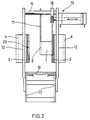
- the structure of the Actuating device 13 can be seen better in FIG. 2.
- the switching switch 1 which is flexible over its entire length transversely to the conveying direction F, is formed in one piece with the separating railing 2.
- the downstream end 8 of the switching switch 1 is defined by the pin 17 rigidly supporting the separating railing.
- the switching switch 1 is held at its downstream end 8 by the pin 17 in the manner of a leaf spring clamped on one side.
- the transition railings 12, each connecting an inlet railing 3 with an outlet railing 4, are - like the switching switch 1 - designed to be flexurally elastic transversely to the conveying direction F.
- the transition railings 12 are each rigidly connected to the inlet railing 3 and outlet railing 4 at their transition points 10 and 11. This design ensures a kink-free, tangential transition of the railings in the extension area 9, even if the inlet railings 3 and outlet railings 4, which are attached to the housing 20 of the conveyor belt 16 by means of adjustable brackets 19, are repositioned to adapt to different vessel formats.
- the inlet railings 3 or transition railings 12 have depressions (23) in the adjustment range of the upstream end 7 of the switching switch 1, which are correspondingly adapted to the contour of the upstream end 7 of the switching switch 1, so that the supply railing 3 and the switching switch 1 have a flush, edge-free Transition contour can form. These depressions or recesses also serve as end stops for the switching switch 1. The depressions are molded into the plastic coating of the railings having a metal core.
- the actuating device 13 e.g. Pneumatic cylinder
- a sliding piece 18 in connection, which is guided transversely to the conveying direction F on a guide element 14 arranged at a distance above parallel to the conveying plane.
- the sliding piece 18 also serves as a holder for the upstream end 7 of the switching switch 1.
- the upstream end 7 is held movable by the sliding piece 18 transversely to the guide axis of the guide element 14.
- the separating railing 2 (see FIG. 1) is arranged approximately in the center of the conveyor belt 16, the parallel running railings 4 being arranged laterally at a distance from the outer edges of the conveyor belt 16. Due to the resulting gap, the vessels 15 are only partially or half supported on their bottom surface. Shards or bottles broken off halfway up can then be expelled downwards through the free gap due to the lack of support by the drain railing 4.
- Fig. 3 shows a second embodiment with two switching switches 1 arranged parallel to one another.
- the single track from a vessel treatment machine 21, e.g. Labeling machine, outflowing containers can be controlled with the Brackets, rotary latches or vacuum devices, equipped outlet star 22 can optionally be supplied to one of the two switching points 1 arranged parallel to one another.
- vascular pulps can alternately be fed to the two switching points, whereby single-lane vascular pulps, e.g. consisting of ten or more vessels, with gaps between them, of approximately the same length. These gaps can be used to switch the switching points 1 as soon as the last vessel of a group has reached the downstream end 8 of a switching point 1, i.e. is located between the partition railing 2 and a drain railing 4.
Landscapes
- Engineering & Computer Science (AREA)
- Mechanical Engineering (AREA)
- Branching, Merging, And Special Transfer Between Conveyors (AREA)
- Attitude Control For Articles On Conveyors (AREA)
- Preparation Of Compounds By Using Micro-Organisms (AREA)
- Framework For Endless Conveyors (AREA)
- Revetment (AREA)
Applications Claiming Priority (2)
| Application Number | Priority Date | Filing Date | Title |
|---|---|---|---|
| DE9211817U DE9211817U1 (zh) | 1992-09-02 | 1992-09-02 | |
| DE9211817U | 1992-09-02 |
Publications (2)
| Publication Number | Publication Date |
|---|---|
| EP0585685A1 EP0585685A1 (de) | 1994-03-09 |
| EP0585685B1 true EP0585685B1 (de) | 1996-01-24 |
Family
ID=6883340
Family Applications (1)
| Application Number | Title | Priority Date | Filing Date |
|---|---|---|---|
| EP93112963A Expired - Lifetime EP0585685B1 (de) | 1992-09-02 | 1993-08-12 | Vorrichtung zum Überleiten eines in einer Reihe einspurig zulaufenden Gefässstromes auf mehrere abführende Förderspuren |
Country Status (9)
| Country | Link |
|---|---|
| US (1) | US5441142A (zh) |
| EP (1) | EP0585685B1 (zh) |
| JP (1) | JPH06179522A (zh) |
| KR (1) | KR0136651B1 (zh) |
| CN (1) | CN1030059C (zh) |
| BR (1) | BR9303625A (zh) |
| CA (1) | CA2105216A1 (zh) |
| DE (2) | DE9211817U1 (zh) |
| ES (1) | ES2083235T3 (zh) |
Cited By (1)
| Publication number | Priority date | Publication date | Assignee | Title |
|---|---|---|---|---|
| EP2364936A2 (de) | 2010-03-09 | 2011-09-14 | Krones AG | Vorrichtung und Verfahren zum Verteilen von Artikeln innerhalb eines Artikelstroms |
Families Citing this family (44)
| Publication number | Priority date | Publication date | Assignee | Title |
|---|---|---|---|---|
| DE9211817U1 (zh) * | 1992-09-02 | 1992-10-29 | Krones Ag Hermann Kronseder Maschinenfabrik, 8402 Neutraubling, De | |
| DE4406561C1 (de) * | 1994-03-01 | 1995-09-07 | Florian Hager | Sortierweiche, insbesondere für Obst und Gemüse |
| GB9512903D0 (en) * | 1995-06-24 | 1995-08-30 | Defabs Eng Systems Ltd | Improvements in or relating to article distribution apparatus |
| US6263883B1 (en) * | 1995-11-02 | 2001-07-24 | Philip Morris Incorporated | Interchange apparatus for a pneumatic conveying system |
| US6244018B1 (en) * | 1997-06-27 | 2001-06-12 | Dallas A. C. Horn & Co. | Air assisted collator |
| DE19963398A1 (de) * | 1999-12-28 | 2001-07-05 | Biforce Anstalt Vaduz | Fördersystem |
| US6810645B2 (en) * | 2001-03-19 | 2004-11-02 | Alain Adrien Cerf | Stabilization of bottles on a conveyor |
| DE20214153U1 (de) * | 2002-09-12 | 2003-03-06 | Heuft Systemtechnik Gmbh | Vorrichtung zum Aufteilen eines ungeordneten Stromes von zylindrischen Gegenständen, zum Beispiel Getränkeflaschen, auf mehrere Gassen |
| AU2003291228A1 (en) * | 2002-11-02 | 2004-06-07 | Ambec, Inc. | Apparatus for diverting successive articles in a single lane to plural lanes |
| FR2849647A1 (fr) * | 2003-01-03 | 2004-07-09 | Meca System | Procede de guidage et dispositif de triage d'objets un par un, au moyen d'un toboggan et d'un couloir flexible |
| ITBO20040244A1 (it) * | 2004-04-22 | 2004-07-22 | Azionaria Costruzioni Acma Spa | Unita' di convogliamento di contenitori |
| NL1027231C2 (nl) * | 2004-10-13 | 2006-04-18 | Townsend Engineering B V | Inrichting en werkwijze voor het positioneren van voortbewegende voedselproducten. |
| US20070102262A1 (en) * | 2005-11-07 | 2007-05-10 | Graham Packaging Company, L.P. | Continuous motion article diverting system |
| DE102006034283A1 (de) * | 2006-06-09 | 2007-12-13 | Krones Ag | Transportvorrichtung |
| MX2008016053A (es) * | 2006-06-13 | 2009-06-05 | Arrowhead Conveyor Corp Inc | Aparato transportador. |
| JP4938391B2 (ja) * | 2006-09-08 | 2012-05-23 | アサヒビール株式会社 | 搬送装置 |
| JP5061756B2 (ja) * | 2007-06-29 | 2012-10-31 | 澁谷工業株式会社 | 容器分岐装置 |
| US7997405B2 (en) | 2009-07-22 | 2011-08-16 | Arrowhead Systems, Inc. | Sanitary conveyor |
| WO2011025732A1 (en) * | 2009-08-24 | 2011-03-03 | Dematic Corp. | Diverter for sorter and method of diverting |
| JP2011111274A (ja) * | 2009-11-26 | 2011-06-09 | Mitsubishi Heavy Industries Food & Packaging Machinery Co Ltd | 容器供給コンベヤ |
| DE102010017724A1 (de) * | 2010-07-05 | 2012-01-05 | Krones Aktiengesellschaft | Geländer für eine Einrichtung zum Transportieren von PET-Flaschen |
| DE102011010162A1 (de) * | 2011-02-02 | 2012-08-02 | Krones Aktiengesellschaft | Verfahren und System zum Ausrichten von Behältern und insbesondere von Flaschen |
| WO2012149962A1 (en) * | 2011-05-03 | 2012-11-08 | Tetra Laval Holdings & Finance S.A. | A divider for dividing products into parallel lanes |
| CN102658956A (zh) * | 2012-04-07 | 2012-09-12 | 凤阳金星实业有限公司 | 一种双轨道输送装置 |
| DE202012007853U1 (de) * | 2012-08-16 | 2013-11-19 | Krones Ag | Vorrichtung zum Ausleiten von Gegenständen |
| CN102874438B (zh) * | 2012-10-16 | 2015-12-16 | 金红叶纸业集团有限公司 | 自动分流控制装置及方法 |
| CN102975891B (zh) * | 2012-10-29 | 2014-11-12 | 杭州永创智能设备股份有限公司 | 一种针对输送线上物品的导向装置 |
| JP5567186B2 (ja) * | 2013-06-10 | 2014-08-06 | 三菱重工食品包装機械株式会社 | 容器供給コンベヤ |
| CN103449092B (zh) * | 2013-08-09 | 2015-09-09 | 嘉兴市新发现机械制造有限公司 | 一种二合一y型收杯接头 |
| DE102013218397A1 (de) * | 2013-09-13 | 2015-03-19 | Krones Ag | Vorrichtung und Verfahren zum Gruppieren von Behältern |
| CN103771115B (zh) * | 2013-12-27 | 2016-06-22 | 广州奥迪通用照明有限公司 | 一种输送线 |
| CN104085671B (zh) * | 2014-06-23 | 2017-01-18 | 楚天科技股份有限公司 | 冻干机多行进料系统及其进料方法 |
| CN104229444A (zh) * | 2014-08-20 | 2014-12-24 | 成都冶金实验厂有限公司 | 一种分道装置 |
| CN104340667A (zh) * | 2014-10-06 | 2015-02-11 | 林允杜 | 一种新型分料机构 |
| CN104444341B (zh) * | 2014-11-28 | 2016-08-10 | 嘉兴鸿利机械有限公司 | 左右分离器 |
| CN104925508A (zh) * | 2015-05-07 | 2015-09-23 | 广西力源宝科技有限公司 | 袋装产品分路输送机 |
| CN105416669B (zh) * | 2015-11-13 | 2018-05-04 | 杭州中亚机械股份有限公司 | 一种分道装置 |
| CN105714419B (zh) * | 2016-04-11 | 2017-11-24 | 青岛天一集团红旗纺织机械有限公司 | 一种粗细联拨叉装置 |
| AU2017307377B2 (en) | 2016-08-05 | 2022-11-24 | Dematic Corp. | Diverter for sorter and method of diverting |
| GB2583119B (en) * | 2019-04-17 | 2022-01-12 | Proseal Uk Ltd | Diverter assembly |
| CN110371604A (zh) * | 2019-07-25 | 2019-10-25 | 浙江海悦自动化机械股份有限公司 | 一种包板机输送等待机构 |
| CN111217124A (zh) * | 2020-01-15 | 2020-06-02 | 南宁学院 | 水果输送分流防碰撞系统 |
| CN114446570B (zh) * | 2022-01-19 | 2023-11-10 | 宁波市信泰科技有限公司 | 一种钕铁硼磁铁的充磁工艺 |
| CN115092460B (zh) * | 2022-08-24 | 2022-11-25 | 苏州澳昆智能机器人技术有限公司 | 一种用于封装有奶酪棒的易撕口包装袋的装箱方法 |
Family Cites Families (12)
| Publication number | Priority date | Publication date | Assignee | Title |
|---|---|---|---|---|
| US2308154A (en) * | 1941-09-24 | 1943-01-12 | Schenley Distillers Corp | Mechanism for handling and feeding bottles and other containers |
| US2451104A (en) * | 1945-11-10 | 1948-10-12 | Riviera Packing Company | Distributing apparatus |
| US2684800A (en) * | 1950-12-16 | 1954-07-27 | Stephen J Lewis | Machine for inserting containers or bottles in cases, crates, or cartons |
| US2670835A (en) * | 1952-03-22 | 1954-03-02 | Charles F Huttmann | Conveyer system |
| DE1103250B (de) * | 1959-01-10 | 1961-03-23 | Deutsche Bundespost | Elektromagnetische Weiche fuer Foerderer von flaechenhaftem Foerdergut |
| FR1387920A (fr) * | 1963-12-04 | 1965-02-05 | Winkler Fallert & Co Maschf | Dispositif d'amenée de pièces de confiserie à une station d'emboîtage |
| DE2227912A1 (de) * | 1972-06-08 | 1973-12-20 | Bauer Eberhard | Weiche zur verteilung laenglicher stueckiger gueter auf zwei foerderbahnen |
| DE2757848A1 (de) * | 1977-12-23 | 1979-06-28 | Agfa Gevaert Ag | Vorrichtung zum sortieren von fotografischen bildern |
| US4723649A (en) * | 1986-07-21 | 1988-02-09 | Hartness International | Apparatus for aligning articles in parallel rows |
| FR2604693B1 (fr) * | 1986-10-03 | 1990-03-23 | Gebo Armaturen | Convoyeur sans pression de bouteilles ou analogues |
| DE3638436A1 (de) * | 1986-11-12 | 1988-05-26 | Kronseder Maschf Krones | Transportvorrichtung fuer gegenstaende, insbesondere an einer etikettiermaschine |
| DE9211817U1 (zh) * | 1992-09-02 | 1992-10-29 | Krones Ag Hermann Kronseder Maschinenfabrik, 8402 Neutraubling, De |
-
1992
- 1992-09-02 DE DE9211817U patent/DE9211817U1/de not_active Expired - Lifetime
-
1993
- 1993-08-12 ES ES93112963T patent/ES2083235T3/es not_active Expired - Lifetime
- 1993-08-12 EP EP93112963A patent/EP0585685B1/de not_active Expired - Lifetime
- 1993-08-12 DE DE59301498T patent/DE59301498D1/de not_active Expired - Lifetime
- 1993-08-30 BR BR9303625A patent/BR9303625A/pt not_active Application Discontinuation
- 1993-08-31 CA CA002105216A patent/CA2105216A1/en not_active Abandoned
- 1993-08-31 US US08/114,805 patent/US5441142A/en not_active Expired - Fee Related
- 1993-09-02 JP JP5218400A patent/JPH06179522A/ja active Pending
- 1993-09-02 KR KR1019930017482A patent/KR0136651B1/ko not_active IP Right Cessation
- 1993-09-02 CN CN93109736A patent/CN1030059C/zh not_active Expired - Fee Related
Cited By (3)
| Publication number | Priority date | Publication date | Assignee | Title |
|---|---|---|---|---|
| EP2364936A2 (de) | 2010-03-09 | 2011-09-14 | Krones AG | Vorrichtung und Verfahren zum Verteilen von Artikeln innerhalb eines Artikelstroms |
| DE102010015888A1 (de) | 2010-03-09 | 2011-09-15 | Krones Ag | Vorrichtung und Verfahren zum Verteilen von Artikeln innerhalb eines Artikelstroms |
| US8544631B2 (en) | 2010-03-09 | 2013-10-01 | Krones Ag | Apparatus and method for distributing articles within a stream of articles |
Also Published As
| Publication number | Publication date |
|---|---|
| KR940006898A (ko) | 1994-04-26 |
| DE9211817U1 (zh) | 1992-10-29 |
| JPH06179522A (ja) | 1994-06-28 |
| CN1030059C (zh) | 1995-10-18 |
| DE59301498D1 (de) | 1996-03-07 |
| EP0585685A1 (de) | 1994-03-09 |
| CA2105216A1 (en) | 1994-03-03 |
| US5441142A (en) | 1995-08-15 |
| KR0136651B1 (ko) | 1998-04-28 |
| CN1084479A (zh) | 1994-03-30 |
| ES2083235T3 (es) | 1996-04-01 |
| BR9303625A (pt) | 1994-03-22 |
Similar Documents
| Publication | Publication Date | Title |
|---|---|---|
| EP0585685B1 (de) | Vorrichtung zum Überleiten eines in einer Reihe einspurig zulaufenden Gefässstromes auf mehrere abführende Förderspuren | |
| DE202006003690U1 (de) | Förderweiche | |
| EP0287845A2 (de) | Anordnung zum Umformen eines mehrspurigen Behälterstroms in mehrere parallele, jeweils durch Einteilelemente voneinander getrennte Behälterreihen | |
| DE202006002351U1 (de) | Vorrichtung zum Auseinanderführen von Gegenständen | |
| DE3310479A1 (de) | Vorrichtung zum wahlweisen umlenken von gegenstaenden auf eines von zwei foerderbaendern, verfahren zu ihrem betrieb und verwendung | |
| EP1043257A2 (de) | Vorrichtung zum Umlenken eines Stroms flacher Produkte in verschiedene Richtungen | |
| DE3529716A1 (de) | Vorrichtung zum ueberfuehren von aufrecht stehenden gefaessen zwischen zwei foerderern mit unterschiedlicher teilung | |
| DE3926735A1 (de) | Verfahren und vorrichtung zum zufuehren von flaschen oder dgl. | |
| DE4343477C1 (de) | Verfahren sowie Vorrichtung zum Verteilen von Behältern oder dergleichen Fördergut auf einen mehrreihigen Förderabschnitt | |
| DE3624411A1 (de) | Vorrichtung zum ueberschieben von verpackungseinheiten zwischen zwei foerdereinrichtungen zu verteil- und aussortierzwecken | |
| DE3422150A1 (de) | Foerdereinrichtung | |
| DE3340088C2 (de) | Vorrichtung zum drucklosen Umformen eines breiten Flaschenstroms zu einem einspurigen Flaschenstrom | |
| DE602004012046T3 (de) | Vorrichtung zur Verbindung einer Verpackungsmaschine, insbesondere einer Blisterherstellungsmaschine, mit einem Zuführförderer für eine Einschachtelmaschine | |
| DE19751967B4 (de) | Einrichtung insbesondere zur Gasseneinteilung bzw. zum Transport,von Transportgut,z. B. Flaschen, Getränkedosen und dergleichen | |
| DE4009515A1 (de) | Vorrichtung zum verbreitern eines einspurig zulaufenden gefaessstromes | |
| DE2627277C2 (de) | Verfahren zum geräuscharmen Zusammenführen von Gefäßen | |
| DE8500522U1 (de) | Vorrichtung zur Zusammenführung eines Flaschenstromes zu einer geschlossenen Flaschenreihe | |
| DE3637250A1 (de) | Vorrichtung zum ueberfuehren von gegenstaenden | |
| EP0193878A2 (de) | Anordnung zum Umformen eines angeförderten breiten Flaschenstroms zu einem abzufördernden einspurigen Flaschenstrom | |
| EP0364894B1 (de) | Vorrichtung zur Zusammenführung eines Behälterstromes zu einer geschlossenen Behälterreihe | |
| EP0227599B1 (de) | Vorrichtung zum Fördern von Gegenständen, insbesondere Flaschen | |
| DE3007104A1 (de) | Transportvorrichtung fuer aufrecht stehende gefaesse | |
| EP1609747B1 (de) | Vorrichtung zum Ausschleusen von auf einer zuführenden Kastenbahn ankommenden Getränkekästen | |
| DE2126313A1 (zh) | ||
| DE4133588A1 (de) | Anordnung zum umformen eines angefoerderten mehrspurigen behaelterstromes in einen abzufoerdernden einspurigen behaelterstrom |
Legal Events
| Date | Code | Title | Description |
|---|---|---|---|
| PUAI | Public reference made under article 153(3) epc to a published international application that has entered the european phase |
Free format text: ORIGINAL CODE: 0009012 |
|
| AK | Designated contracting states |
Kind code of ref document: A1 Designated state(s): DE ES FR GB IT |
|
| 17P | Request for examination filed |
Effective date: 19940131 |
|
| 17Q | First examination report despatched |
Effective date: 19950321 |
|
| GRAA | (expected) grant |
Free format text: ORIGINAL CODE: 0009210 |
|
| AK | Designated contracting states |
Kind code of ref document: B1 Designated state(s): DE ES FR GB IT |
|
| ITF | It: translation for a ep patent filed |
Owner name: PATRITO BREVETTI |
|
| ET | Fr: translation filed | ||
| GBT | Gb: translation of ep patent filed (gb section 77(6)(a)/1977) |
Effective date: 19960125 |
|
| REF | Corresponds to: |
Ref document number: 59301498 Country of ref document: DE Date of ref document: 19960307 |
|
| REG | Reference to a national code |
Ref country code: ES Ref legal event code: FG2A Ref document number: 2083235 Country of ref document: ES Kind code of ref document: T3 |
|
| PLBE | No opposition filed within time limit |
Free format text: ORIGINAL CODE: 0009261 |
|
| STAA | Information on the status of an ep patent application or granted ep patent |
Free format text: STATUS: NO OPPOSITION FILED WITHIN TIME LIMIT |
|
| 26N | No opposition filed | ||
| PGFP | Annual fee paid to national office [announced via postgrant information from national office to epo] |
Ref country code: ES Payment date: 20000816 Year of fee payment: 8 |
|
| PG25 | Lapsed in a contracting state [announced via postgrant information from national office to epo] |
Ref country code: ES Free format text: LAPSE BECAUSE OF NON-PAYMENT OF DUE FEES Effective date: 20010813 |
|
| REG | Reference to a national code |
Ref country code: GB Ref legal event code: IF02 |
|
| PGFP | Annual fee paid to national office [announced via postgrant information from national office to epo] |
Ref country code: GB Payment date: 20020722 Year of fee payment: 10 |
|
| PGFP | Annual fee paid to national office [announced via postgrant information from national office to epo] |
Ref country code: FR Payment date: 20020820 Year of fee payment: 10 |
|
| PG25 | Lapsed in a contracting state [announced via postgrant information from national office to epo] |
Ref country code: GB Free format text: LAPSE BECAUSE OF NON-PAYMENT OF DUE FEES Effective date: 20030812 |
|
| GBPC | Gb: european patent ceased through non-payment of renewal fee |
Effective date: 20030812 |
|
| REG | Reference to a national code |
Ref country code: ES Ref legal event code: FD2A Effective date: 20020911 |
|
| PG25 | Lapsed in a contracting state [announced via postgrant information from national office to epo] |
Ref country code: FR Free format text: LAPSE BECAUSE OF NON-PAYMENT OF DUE FEES Effective date: 20040430 |
|
| REG | Reference to a national code |
Ref country code: FR Ref legal event code: ST |
|
| PG25 | Lapsed in a contracting state [announced via postgrant information from national office to epo] |
Ref country code: IT Free format text: LAPSE BECAUSE OF NON-PAYMENT OF DUE FEES;WARNING: LAPSES OF ITALIAN PATENTS WITH EFFECTIVE DATE BEFORE 2007 MAY HAVE OCCURRED AT ANY TIME BEFORE 2007. THE CORRECT EFFECTIVE DATE MAY BE DIFFERENT FROM THE ONE RECORDED. Effective date: 20050812 |
|
| PGFP | Annual fee paid to national office [announced via postgrant information from national office to epo] |
Ref country code: DE Payment date: 20090806 Year of fee payment: 17 |
|
| REG | Reference to a national code |
Ref country code: DE Ref legal event code: R119 Ref document number: 59301498 Country of ref document: DE Effective date: 20110301 |
|
| PG25 | Lapsed in a contracting state [announced via postgrant information from national office to epo] |
Ref country code: DE Free format text: LAPSE BECAUSE OF NON-PAYMENT OF DUE FEES Effective date: 20110301 |