EP0585685B1 - Apparatus for transfering a single arriving stream of aligned containers to several discharge tracks - Google Patents
Apparatus for transfering a single arriving stream of aligned containers to several discharge tracks Download PDFInfo
- Publication number
- EP0585685B1 EP0585685B1 EP93112963A EP93112963A EP0585685B1 EP 0585685 B1 EP0585685 B1 EP 0585685B1 EP 93112963 A EP93112963 A EP 93112963A EP 93112963 A EP93112963 A EP 93112963A EP 0585685 B1 EP0585685 B1 EP 0585685B1
- Authority
- EP
- European Patent Office
- Prior art keywords
- rails
- switched point
- containers
- inflow
- switched
- Prior art date
- Legal status (The legal status is an assumption and is not a legal conclusion. Google has not performed a legal analysis and makes no representation as to the accuracy of the status listed.)
- Expired - Lifetime
Links
- 230000007704 transition Effects 0.000 claims description 19
- 238000011144 upstream manufacturing Methods 0.000 claims description 10
- 238000005452 bending Methods 0.000 claims 4
- 238000000638 solvent extraction Methods 0.000 claims 4
- 230000015572 biosynthetic process Effects 0.000 claims 1
- 239000012634 fragment Substances 0.000 claims 1
- 238000000034 method Methods 0.000 description 4
- 230000002792 vascular Effects 0.000 description 4
- 238000011161 development Methods 0.000 description 3
- 230000018109 developmental process Effects 0.000 description 3
- 238000012546 transfer Methods 0.000 description 3
- 238000013461 design Methods 0.000 description 2
- 238000002372 labelling Methods 0.000 description 2
- 238000004806 packaging method and process Methods 0.000 description 2
- 239000006063 cullet Substances 0.000 description 1
- 230000001419 dependent effect Effects 0.000 description 1
- 230000002349 favourable effect Effects 0.000 description 1
- 239000008141 laxative Substances 0.000 description 1
- 230000002475 laxative effect Effects 0.000 description 1
- 239000002184 metal Substances 0.000 description 1
- 238000012856 packing Methods 0.000 description 1
- 238000005192 partition Methods 0.000 description 1
- 239000006223 plastic coating Substances 0.000 description 1
Images


Classifications
-
- B—PERFORMING OPERATIONS; TRANSPORTING
- B65—CONVEYING; PACKING; STORING; HANDLING THIN OR FILAMENTARY MATERIAL
- B65G—TRANSPORT OR STORAGE DEVICES, e.g. CONVEYORS FOR LOADING OR TIPPING, SHOP CONVEYOR SYSTEMS OR PNEUMATIC TUBE CONVEYORS
- B65G47/00—Article or material-handling devices associated with conveyors; Methods employing such devices
- B65G47/02—Devices for feeding articles or materials to conveyors
- B65G47/04—Devices for feeding articles or materials to conveyors for feeding articles
- B65G47/06—Devices for feeding articles or materials to conveyors for feeding articles from a single group of articles arranged in orderly pattern, e.g. workpieces in magazines
- B65G47/08—Devices for feeding articles or materials to conveyors for feeding articles from a single group of articles arranged in orderly pattern, e.g. workpieces in magazines spacing or grouping the articles during feeding
-
- B—PERFORMING OPERATIONS; TRANSPORTING
- B65—CONVEYING; PACKING; STORING; HANDLING THIN OR FILAMENTARY MATERIAL
- B65G—TRANSPORT OR STORAGE DEVICES, e.g. CONVEYORS FOR LOADING OR TIPPING, SHOP CONVEYOR SYSTEMS OR PNEUMATIC TUBE CONVEYORS
- B65G47/00—Article or material-handling devices associated with conveyors; Methods employing such devices
- B65G47/52—Devices for transferring articles or materials between conveyors i.e. discharging or feeding devices
- B65G47/68—Devices for transferring articles or materials between conveyors i.e. discharging or feeding devices adapted to receive articles arriving in one layer from one conveyor lane and to transfer them in individual layers to more than one conveyor lane or to one broader conveyor lane, or vice versa, e.g. combining the flows of articles conveyed by more than one conveyor
- B65G47/71—Devices for transferring articles or materials between conveyors i.e. discharging or feeding devices adapted to receive articles arriving in one layer from one conveyor lane and to transfer them in individual layers to more than one conveyor lane or to one broader conveyor lane, or vice versa, e.g. combining the flows of articles conveyed by more than one conveyor the articles being discharged or distributed to several distinct separate conveyors or to a broader conveyor lane
-
- B—PERFORMING OPERATIONS; TRANSPORTING
- B65—CONVEYING; PACKING; STORING; HANDLING THIN OR FILAMENTARY MATERIAL
- B65G—TRANSPORT OR STORAGE DEVICES, e.g. CONVEYORS FOR LOADING OR TIPPING, SHOP CONVEYOR SYSTEMS OR PNEUMATIC TUBE CONVEYORS
- B65G47/00—Article or material-handling devices associated with conveyors; Methods employing such devices
- B65G47/02—Devices for feeding articles or materials to conveyors
- B65G47/04—Devices for feeding articles or materials to conveyors for feeding articles
-
- B—PERFORMING OPERATIONS; TRANSPORTING
- B65—CONVEYING; PACKING; STORING; HANDLING THIN OR FILAMENTARY MATERIAL
- B65G—TRANSPORT OR STORAGE DEVICES, e.g. CONVEYORS FOR LOADING OR TIPPING, SHOP CONVEYOR SYSTEMS OR PNEUMATIC TUBE CONVEYORS
- B65G47/00—Article or material-handling devices associated with conveyors; Methods employing such devices
- B65G47/22—Devices influencing the relative position or the attitude of articles during transit by conveyors
Definitions
- the invention relates to a device for transferring a vessel stream tapering in one row to a plurality of discharge conveyor tracks according to the preamble of claim 1.
- Such devices are known in various versions from the patent literature (DE-A-2 227 912, US Pat. No. 2,684,800 and US Pat. No. 2,308,154). They are used in filling and packaging lines when it is necessary to divide a single-track container flow over several conveyor tracks, for example to supply packaging machines with multiple tracks to containers. In bottle filling lines, this is necessary in the area between the single-track labeling machine and the subsequent multi-track bottle packing machine for inserting the bottles into boxes or cartons.
- switching points or flaps have been used for transferring the single-track vessels, the rigid guide surface of which can be pivoted into the conveying path of the single-track vessels.
- a disadvantage of these devices is the uneasy vascular guidance during the transfer process and the resulting impulse noise and vascular stress.
- the invention has for its object to improve a generic device for transferring a tapered stream flowing in a row to several laxative conveyor tracks in such a way that a quiet, vessel-friendly and low-noise vessel guidance is ensured during the transfer process even at high delivery rates.
- edge-free and kink-free guidance of the vessels can be achieved during the entire transfer process, so that a smooth and uniform vessel guidance is ensured even at very high conveying speeds.
- the tangential transition of the surface of the inlet railing to the switching switch and from there to the subsequent separating railing contributes to this.
- An absolutely flush transition of the surface of the inlet railing to the surface of the switch gate is achieved by recesses or recesses in the inlet railing for receiving the end of the switch gate which can be moved transversely to the conveying direction.
- a particularly advantageous development of the invention provides for a seamless transition of the inlet railings leading the single-track vessel flow into the outlet railings, the railings merging into one another close to the switching switch, forming an extension area.
- a particularly favorable contour course of the transition railings connecting the inlet railings to the outlet railings is achieved if they are designed to be flexurally elastic over their entire length in the extension area. This enables a tangential, rounded and kink-free transition of the railings to be achieved at the transition points.
- the switching switch itself is at least in sections, i.e. at their upstream and downstream ends, designed to be flexible. It is even more advantageous to use a switching switch that is flexible over its entire length, since the contour of the switching switch in both switching positions can then be congruent to the contour of the railing opposite each other in the extension area. A congruent contour course between the switching switch and the opposite, fixed railing ensures a constant distance between the two contours when viewed in the conveying direction for exact guidance of the vessels.
- the switching switch is formed in one piece with the separating railing which adjoins in the conveying direction, the part forming the switching switch over the entire length is designed to be flexible.
- the vessels 15 are transported upright on a conveyor belt 16 in the conveying direction F.
- inlet railings 3 are arranged on both sides of the conveyor belt, each of which - seen in the conveying direction F - open into an S-shaped transition railing 12 in an extension area 9, to which an outlet railing 4 connects.
- a separating railing 2 is arranged between the two opposite drain railings 4 and is held by pins 17 from above.
- the switching switch 1 is arranged in the extension area 9 between the two transition railings 12.
- the upstream end 7 of the switching switch 1 can be alternately transferred from an inlet railing 3 to the opposite inlet railing by means of an actuating device 13 transversely to the conveying direction F.
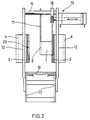
- the structure of the Actuating device 13 can be seen better in FIG. 2.
- the switching switch 1 which is flexible over its entire length transversely to the conveying direction F, is formed in one piece with the separating railing 2.
- the downstream end 8 of the switching switch 1 is defined by the pin 17 rigidly supporting the separating railing.
- the switching switch 1 is held at its downstream end 8 by the pin 17 in the manner of a leaf spring clamped on one side.
- the transition railings 12, each connecting an inlet railing 3 with an outlet railing 4, are - like the switching switch 1 - designed to be flexurally elastic transversely to the conveying direction F.
- the transition railings 12 are each rigidly connected to the inlet railing 3 and outlet railing 4 at their transition points 10 and 11. This design ensures a kink-free, tangential transition of the railings in the extension area 9, even if the inlet railings 3 and outlet railings 4, which are attached to the housing 20 of the conveyor belt 16 by means of adjustable brackets 19, are repositioned to adapt to different vessel formats.
- the inlet railings 3 or transition railings 12 have depressions (23) in the adjustment range of the upstream end 7 of the switching switch 1, which are correspondingly adapted to the contour of the upstream end 7 of the switching switch 1, so that the supply railing 3 and the switching switch 1 have a flush, edge-free Transition contour can form. These depressions or recesses also serve as end stops for the switching switch 1. The depressions are molded into the plastic coating of the railings having a metal core.
- the actuating device 13 e.g. Pneumatic cylinder
- a sliding piece 18 in connection, which is guided transversely to the conveying direction F on a guide element 14 arranged at a distance above parallel to the conveying plane.
- the sliding piece 18 also serves as a holder for the upstream end 7 of the switching switch 1.
- the upstream end 7 is held movable by the sliding piece 18 transversely to the guide axis of the guide element 14.
- the separating railing 2 (see FIG. 1) is arranged approximately in the center of the conveyor belt 16, the parallel running railings 4 being arranged laterally at a distance from the outer edges of the conveyor belt 16. Due to the resulting gap, the vessels 15 are only partially or half supported on their bottom surface. Shards or bottles broken off halfway up can then be expelled downwards through the free gap due to the lack of support by the drain railing 4.
- Fig. 3 shows a second embodiment with two switching switches 1 arranged parallel to one another.
- the single track from a vessel treatment machine 21, e.g. Labeling machine, outflowing containers can be controlled with the Brackets, rotary latches or vacuum devices, equipped outlet star 22 can optionally be supplied to one of the two switching points 1 arranged parallel to one another.
- vascular pulps can alternately be fed to the two switching points, whereby single-lane vascular pulps, e.g. consisting of ten or more vessels, with gaps between them, of approximately the same length. These gaps can be used to switch the switching points 1 as soon as the last vessel of a group has reached the downstream end 8 of a switching point 1, i.e. is located between the partition railing 2 and a drain railing 4.
Landscapes
- Engineering & Computer Science (AREA)
- Mechanical Engineering (AREA)
- Branching, Merging, And Special Transfer Between Conveyors (AREA)
- Attitude Control For Articles On Conveyors (AREA)
- Framework For Endless Conveyors (AREA)
- Preparation Of Compounds By Using Micro-Organisms (AREA)
- Revetment (AREA)
Description
Die Erfindung betrifft eine Vorrichtung zum Überleiten eines in einer Reihe einspurig zulaufenden Gefäßstromes auf mehrere abführende Förderspuren gemäß dem Oberbegriff des Anspruchs 1.The invention relates to a device for transferring a vessel stream tapering in one row to a plurality of discharge conveyor tracks according to the preamble of claim 1.
Derartige Vorrichtungen sind in verschiedenen Ausführungen aus der Patentliteratur (DE-A-2 227 912, US-PS 2 684 800 und US-PS 2 308 154) bekannt. Sie werden in Füll- und Verpackungslinien eingesetzt, wenn eine Aufteilung eines einspurigen Gefäßstromes auf mehrere Förderspuren erforderlich ist, um beispielsweise mehrspurig arbeitende Verpackungsmaschinen mit Gefäßen zu versorgen. In Flaschenfüllinien ist dies im Bereich zwischen der einspurig arbeitenden Etikettiermaschine und der danach folgenden mehrspurig arbeitenden Flascheneinpackmaschine zum Einsetzen der Flaschen in Kästen oder Kartons erforderlich.Such devices are known in various versions from the patent literature (DE-A-2 227 912, US Pat. No. 2,684,800 and US Pat. No. 2,308,154). They are used in filling and packaging lines when it is necessary to divide a single-track container flow over several conveyor tracks, for example to supply packaging machines with multiple tracks to containers. In bottle filling lines, this is necessary in the area between the single-track labeling machine and the subsequent multi-track bottle packing machine for inserting the bottles into boxes or cartons.
Bisher wurden zum Überleiten der einspurig zulaufenden Gefäße Schaltweichen oder -klappen eingesetzt, deren starre Leitfläche in den Förderweg der einspurig zulaufenden Gefäße geschwenkt werden kann. Als nachteilig werden bei diesen Vorrichtungen die unruhige Gefäßführung während des Überleitvorganges und die daraus resultierenden Impulsgeräusche und Gefäßbeanspruchung empfunden.So far, switching points or flaps have been used for transferring the single-track vessels, the rigid guide surface of which can be pivoted into the conveying path of the single-track vessels. A disadvantage of these devices is the uneasy vascular guidance during the transfer process and the resulting impulse noise and vascular stress.
Demzufolge liegt der Erfindung die Aufgabe zugrunde, eine gattungsgemäße Vorrichtung zum Überleiten eines in einer Reihe einspurig zulaufenden Gefäßstromes auf mehrere abführende Förderspuren dahingehend zu verbessern, daß auch bei hohen Förderleistungen eine ruhige, gefäßschonende und geräuscharme Gefäßführung während des Überleitvorganges gewährleistet ist.Accordingly, the invention has for its object to improve a generic device for transferring a tapered stream flowing in a row to several laxative conveyor tracks in such a way that a quiet, vessel-friendly and low-noise vessel guidance is ensured during the transfer process even at high delivery rates.
Diese Aufgabe wird durch die im kennzeichnenden Teil des Anspruchs 1 angegebenen Merkmale gelöst.This object is achieved by the features specified in the characterizing part of claim 1.
Durch die biegeelastische Ausbildung der Schaltweiche kann eine kanten- und knickfreie Führung der Gefäße während des gesamten Überleitvorganges bewerkstelligt werden, so daß auch bei sehr hohen Fördergeschwindigkeiten eine ruhige und gleichmäßige Gefäßführung sichergestellt ist. Dazu trägt der tangentiale Übergang der Oberfläche der Zulaufgeländer zur Schaltweiche und von dieser auf das nachfolgende Trenngeländer bei. Ein absolut bündiger Übergang der Oberfläche des Zulaufgeländers auf die Oberfläche der Schaltweiche wird durch Vertiefungen oder Aussparungen im Zulaufgeländer zur Aufnahme des quer zur Förderrichtung bewegbaren Endes der Schaltweiche erreicht.Due to the bending-elastic design of the switching switch, edge-free and kink-free guidance of the vessels can be achieved during the entire transfer process, so that a smooth and uniform vessel guidance is ensured even at very high conveying speeds. The tangential transition of the surface of the inlet railing to the switching switch and from there to the subsequent separating railing contributes to this. An absolutely flush transition of the surface of the inlet railing to the surface of the switch gate is achieved by recesses or recesses in the inlet railing for receiving the end of the switch gate which can be moved transversely to the conveying direction.
Eine besonders vorteilhafte Weiterbildung der Erfindung sieht einen nahtlosen Übergang der den einspurigen Gefäßstrom führenden Zulaufgeländer in die Ablaufgeländer vor, wobei die Geländer nahe der Schaltweiche unter Ausbildung eines Erweiterungsbereiches ineinander übergehen. Ein besonders günstiger Konturverlauf der die Zulaufgeländer mit den Ablaufgeländern verbindenden Übergangsgeländer wird dann erzielt, wenn diese im Erweiterungsbereich möglichst über ihre gesamte Länge biegeelastisch ausgebildet sind. Dadurch kann an den Übergangsstellen ein tangentialer, abgerundeter und knickfreier Übergang der Geländer erzielt werden.A particularly advantageous development of the invention provides for a seamless transition of the inlet railings leading the single-track vessel flow into the outlet railings, the railings merging into one another close to the switching switch, forming an extension area. A particularly favorable contour course of the transition railings connecting the inlet railings to the outlet railings is achieved if they are designed to be flexurally elastic over their entire length in the extension area. This enables a tangential, rounded and kink-free transition of the railings to be achieved at the transition points.
Die Schaltweiche selbst ist zumindest abschnittsweise, d.h. an ihrem stromaufwärtigen und stromabwärtigen Ende, biegeelastisch ausgebildet. Noch günstiger ist die Verwendung einer über ihre gesamte Länge biegeelastischen Schaltweiche, da sich dann die Kontur der Schaltweiche in beiden Schaltstellungen kongruent zum Konturverlauf des im Erweiterungsbereich jeweils gegenüberliegenden Geländers ausformen kann. Ein kongruenter Konturverlauf zwischen der Schaltweiche und dem gegenüberliegenden, feststehenden Geländer gewährleistet einen in Förderrichtung gesehen konstanten Abstand zwischen den beiden Konturen zur exakten Führung der Gefäße.The switching switch itself is at least in sections, i.e. at their upstream and downstream ends, designed to be flexible. It is even more advantageous to use a switching switch that is flexible over its entire length, since the contour of the switching switch in both switching positions can then be congruent to the contour of the railing opposite each other in the extension area. A congruent contour course between the switching switch and the opposite, fixed railing ensures a constant distance between the two contours when viewed in the conveying direction for exact guidance of the vessels.
Gemäß einer vorteilhaften Weiterbildung der Erfindung ist die Schaltweiche einstückig mit dem in Förderrichtung anschließenden Trenngeländer ausgebildet wobei der die Schaltweiche bildende Teil über die gesamte Länge biegeelastisch ausgeführt ist. Weitere vorteilhafte Weiterbildungen der Erfindung sind Gegenstand der Unteransprüche.According to an advantageous development of the invention, the switching switch is formed in one piece with the separating railing which adjoins in the conveying direction, the part forming the switching switch over the entire length is designed to be flexible. Further advantageous developments of the invention are the subject of the dependent claims.
Nachfolgend werden zwei Ausführungsbeispiele anhand der Figuren erläutert. Es zeigen:
- Fig. 1
- ein erstes Ausführungsbeispiel in der Draufsicht,
- Fig. 2
- einen senkrechten Schnitt entlang der Linie A-A in Fig. 1 und
- Fig. 3
- ein zweites Ausführungsbeispiel in der Draufsicht.
- Fig. 1
- a first embodiment in plan view,
- Fig. 2
- a vertical section along the line AA in Fig. 1 and
- Fig. 3
- a second embodiment in plan view.
Die Gefäße 15 werden aufrecht auf einem Förderband 16 stehend in Förderrichtung F transportiert. Oberhalb der durch das Förderband 16 gebildeten Förderebene sind an beiden Seiten des Förderbandes Zulaufgeländer 3 angeordnet, die jeweils - in Förderrichtung F gesehen - in einem Erweiterungsbereich 9 in ein S-förmiges Übergangsgeländer 12 einmünden, an das sich ein Ablaufgeländer 4 anschließt. Zwischen den beiden gegenüberliegenden Ablaufgeländern 4 ist ein Trenngeländer 2 angeordnet, das von oben her durch Zapfen 17 gehalten wird.The
Im Erweiterungsbereich 9 ist zwischen den beiden Übergangsgeländern 12 die Schaltweiche 1 angeordnet. Das stromaufwärtige Ende 7 der Schaltweiche 1 kann mittels einer Betätigungseinrichtung 13 quer zur Förderrichtung F von einem Zulaufgeländer 3 zum gegenüberliegenden Zulaufgeländer wechselweise überführt werden. Der Aufbau der Betätigungseinrichtung 13 ist in Fig. 2 besser erkennbar.The switching switch 1 is arranged in the extension area 9 between the two
Bei dem in Fig. 1 dargestellten Ausführungsbeispiel ist die über ihre gesamte Länge quer zur Förderrichtung F biegeelastische Schaltweiche 1 einstückig mit dem Trenngeländer 2 ausgebildet. Das stromabwärtige Ende 8 der Schaltweiche 1 wird durch den das Trenngeländer starr tragenden Zapfen 17 definiert. Die Schaltweiche 1 wird an ihrem stromabwärtigen Ende 8 durch den Zapfen 17 nach Art einer einseitig eingespannten Blattfeder gehalten.In the embodiment shown in FIG. 1, the switching switch 1, which is flexible over its entire length transversely to the conveying direction F, is formed in one piece with the separating
Die jeweils ein Zulaufgeländer 3 mit einem Ablaufgeländer 4 verbindenden Übergangsgeländer 12 sind - ähnlich der Schaltweiche 1 - quer zur Förderrichtung F biegeelastisch ausgebildet. Die Übergangsgeländer 12 sind an ihren Übergangsstellen 10 und 11 jeweils starr mit dem Zulaufgeländer 3 und Ablaufgeländer 4 verbunden. Diese Ausführung gewährleistet einen knickfreien, tangentialen Übergang der Geländer im Erweiterungsbereich 9, selbst wenn die zur Anpassung an verschiedene Gefäßformate quer zur Förderrichtung F mittels einstellbarer Halterungen 19 am Gehäuse 20 des Förderbandes 16 befestigten Zulaufgeländer 3 und Ablaufgeländer 4 neu positioniert werden.The
Die Zulaufgeländer 3 bzw. Übergangsgeländer 12 weisen im Verstellbereich des stromaufwärtigen Endes 7 der Schaltweiche 1 Vertiefungen (23) auf, die entsprechend an die Kontur des stromaufwärtigen Endes 7 der Schaltweiche 1 angepaßt sind, damit das Zulaufgeländer 3 und die Schaltweiche 1 eine bündige, kantenfreie Übergangskontur bilden können. Diese Vertiefungen oder Aussparungen dienen zugleich als Endanschläge für die Schaltweiche 1. Die Vertiefungen sind in die Kunststoffummantelung der einen Metallkern aufweisenden Geländer eingeformt.The
Wie in Fig. 2 erkennbar ist, steht die durch eine nicht dargestellte Steuereinrichtung ansteuerbare Betätigungseinrichtung 13, z.B. Pneumatikzylinder, mit einem Schiebestück 18 in Verbindung, welches quer zur Förderrichtung F verschiebbar auf einem mit Abstand oberhalb parallel zur Förderebene angeordneten Führungselement 14 geführt ist. Das Schiebestück 18 dient zugleich als Halterung des stromaufwärtigen Endes 7 der Schaltweiche 1. Zum Längenausgleich beim Schaltvorgang wird das stromaufwärtige Ende 7 quer zur Führungsachse des Führungselements 14 beweglich durch das Schiebestück 18 gehalten.As can be seen in Fig. 2, the actuating
Zur Ausscheidung von Scherben oder teilweise gebrochenen Flaschen ist das Trenngeländer 2 (siehe Fig. 1) in etwa mittig zum Förderband 16 angeordnet, wobei die parallel verlaufenden Ablaufgeländer 4 seitlich mit Abstand zu den äußeren Rändern des Förderbandes 16 angeordnet sind. Bedingt durch den dadurch entstehenden Spalt werden die Gefäße 15 nur teilweise bzw. halbseitig an ihrer Bodenfläche unterstützt gehalten. Scherben oder auf halber Höhe abgebrochene Flaschen können dann aufgrund der fehlenden Abstützung durch das Ablaufgeländer 4 durch den freien Spalt nach unten ausgeschieden werden.To separate cullet or partially broken bottles, the separating railing 2 (see FIG. 1) is arranged approximately in the center of the
Fig. 3 zeigt ein zweites Ausführungsbeispiel mit zwei parallel zueinander angeordneten Schaltweichen 1. Die einspurig aus einer Gefäßbehandlungsmaschine 21, z.B. Etikettiermaschine, auslaufenden Gefäße können mit Hilfe eines mit ansteuerbaren Halteeinrichtungen, z.B. Klammern, Drehriegel oder Vakuumeinrichtungen, ausgestatteten Auslaufsterns 22 wahlweise einer der beiden parallel zueinander angeordneten Schaltweichen 1 zugeführt werden. Es können beispielsweise abwechselnd Gefäßpulks den beiden Schaltweichen zugeleitet werden, wodurch auf den beiden einspurigen, zu den Schaltweichen 1 führenden Förderspuren einspurige Gefäßpulks, z.B. bestehend aus zehn oder mehr Gefäßen, mit dazwischenliegenden, in etwa gleich langen Lücken entstehen. Diese Lücken können zum Umschalten der Schaltweichen 1 genützt werden, sobald das letzte Gefäß eines Pulks das stromabwärtige Ende 8 einer Schaltweiche 1 erreicht hat, d.h. sich zwischen dem Trenngeländer 2 und einem Ablaufgeländer 4 befindet.Fig. 3 shows a second embodiment with two switching switches 1 arranged parallel to one another. The single track from a
Claims (22)
- Device for transferring an incoming stream of containers in single file to a plurality of discharge conveyor tracks (5, 6), preferably two, with the aid of a switched point (1) which serves as a deflecting surface and the end (7) of which pointing upstream to the incoming stream of containers in single file is adjustable essentially transversely to the transport direction (F), characterised in that the switched point (1) is constructed in elastically bending manner at least in sections and its end (8) pointing downstream is held or guided in immovable manner transversely to the transport direction (F).
- Device according to claim 1, characterised in that a partitioning rail (2) associated with the discharge conveyor tracks (5, 6) adjoins the switched point (1) at the end (8) pointing downstream.
- Device according to at least one of the preceding claims, characterised in that the incoming stream of containers in single file is guided laterally by two inflow rails (3) extending at a distance parallel to one another in the region ahead of the switched point (1).
- Device according to at least one of the preceding claims, characterised in that in the multiple-track conveyor region (5, 6), outflow rails (4) extending at a distance parallel to the partitioning rail (2) are arranged.
- Device according to at least one of the preceding claims, characterised in that close to the switched point (1) the inflow rails (3) pass over, in particular in S-shaped manner, into the outflow rails (4) of the multiple-track conveyor region (5, 6) with formation of an expansion region (9).
- Device according to at least one of the preceding claims, characterised in that in the pivot region of the switched point (1) the inflow rails (3) comprise depressions or recesses (23) for receiving the upstream end (7) of the switched point (1).
- Device according to at least one of the preceding claims, characterised in that the switched point (1) is constructed in elastically bending manner at least at its two ends (7,8) and its contour at the transition locations (10, 11) passes over tangentially into the surface of the inflow rails (3) and of the partitioning rail (2).
- Device according to at least one of the preceding claims, characterised in that the transition rails (12) connecting the inflow rails (3) to the outflow rails (4) in the expansion region (9) are constructed in elastically bending manner.
- Device according to claim 8, characterised in that in the expansion region (9) the distance between the contour of the switched point (1) guiding the containers and the outwardly located transition rails (12) is constant in the transport direction (F).
- Device according to at least one of the preceding claims, characterised in that over its entire length the switched point (1) is constructed in elastically bending manner, in particular in the fashion of a leaf spring clamped at one end.
- Device according to at least one of the preceding claims, characterised in that the switched point (1) is constructed in one piece with the partitioning rail (2).
- Device according to at least one of the preceding claims, characterised in that a controllable actuating device (13) is associated with the upstream end (7) of the switched point (1).
- Device according to at least one of the preceding claims, characterised in that the upstream end (7) of the switched point (1) is connected to a guidance element (14) movable transversely to the transport direction (F).
- Device according to at least one of the preceding claims, characterised in that the switched point (1) is held movably at the guidance element (14) essentially transversely to the guide axis of the guidance element (14).
- Device according to at least one of the preceding claims, characterised in that the actuating device (13) and the guidance element (14) are arranged at a distance above the transport plane, wherein the guide axis of the guidance element (14) extends parallel to the transport plane.
- Device according to at least one of the preceding claims, characterised in that the inflow rails (3) and outflow rails (4) are fixed in adjustable manner transversely to the transport direction (F) for adapting to different container shapes.
- Device according to at least one of the preceding claims, characterised in that the containers (15) are fed to the switched point (1) with spacing between them or in groups.
- Device according to at least one of the preceding claims, characterised in that several switched points (1) are arranged parallel to one another.
- Device according to at least one of the preceding claims, characterised in that an uninterrupted incoming row of containers in single file is distributed in groups to at least two transport tracks, wherein each of the two transport tracks leads to at least one switched point (1).
- Device according to at least one of the preceding claims, characterised in that the containers are transported standing upright on one or several conveyor belts and are held with only partial or semilateral support at their base surface by a conveyor belt for separating out fragments or toppled containers along the inflow rails (3) and/or outflow rails (4).
- Device according to at least one of the preceding claims, characterised in that in the expansion region (9) the inflow (3), transition (12) and outflow rails (4) pass over into one another in seamless manner without edges or sharp bends and are preferably constructed in one piece.
- Device according to at least one of the preceding claims, characterised in that the contour of the switched point (1) in both switching positions is constructed essentially congruent to the contour of the respective opposite transition rail (12) in the expansion region (9).
Applications Claiming Priority (2)
| Application Number | Priority Date | Filing Date | Title |
|---|---|---|---|
| DE9211817U DE9211817U1 (en) | 1992-09-02 | 1992-09-02 | Device for transferring a vessel stream running in a single lane to several discharge conveyor tracks |
| DE9211817U | 1992-09-02 |
Publications (2)
| Publication Number | Publication Date |
|---|---|
| EP0585685A1 EP0585685A1 (en) | 1994-03-09 |
| EP0585685B1 true EP0585685B1 (en) | 1996-01-24 |
Family
ID=6883340
Family Applications (1)
| Application Number | Title | Priority Date | Filing Date |
|---|---|---|---|
| EP93112963A Expired - Lifetime EP0585685B1 (en) | 1992-09-02 | 1993-08-12 | Apparatus for transfering a single arriving stream of aligned containers to several discharge tracks |
Country Status (9)
| Country | Link |
|---|---|
| US (1) | US5441142A (en) |
| EP (1) | EP0585685B1 (en) |
| JP (1) | JPH06179522A (en) |
| KR (1) | KR0136651B1 (en) |
| CN (1) | CN1030059C (en) |
| BR (1) | BR9303625A (en) |
| CA (1) | CA2105216A1 (en) |
| DE (2) | DE9211817U1 (en) |
| ES (1) | ES2083235T3 (en) |
Cited By (1)
| Publication number | Priority date | Publication date | Assignee | Title |
|---|---|---|---|---|
| EP2364936A2 (en) | 2010-03-09 | 2011-09-14 | Krones AG | Device and method for distributing items within a flow of items |
Families Citing this family (44)
| Publication number | Priority date | Publication date | Assignee | Title |
|---|---|---|---|---|
| DE9211817U1 (en) * | 1992-09-02 | 1992-10-29 | KRONES AG, 93073 Neutraubling | Device for transferring a vessel stream running in a single lane to several discharge conveyor tracks |
| DE4406561C1 (en) * | 1994-03-01 | 1995-09-07 | Florian Hager | Switch-over frame for sorting fruit and vegetables |
| GB9512903D0 (en) * | 1995-06-24 | 1995-08-30 | Defabs Eng Systems Ltd | Improvements in or relating to article distribution apparatus |
| BR9611437A (en) * | 1995-11-02 | 1999-03-23 | Tabac Fab Reunies Sa | Needle for a pneumatic conveying system |
| US6244018B1 (en) * | 1997-06-27 | 2001-06-12 | Dallas A. C. Horn & Co. | Air assisted collator |
| DE19963398A1 (en) * | 1999-12-28 | 2001-07-05 | Biforce Anstalt Vaduz | Conveyor system |
| US6810645B2 (en) * | 2001-03-19 | 2004-11-02 | Alain Adrien Cerf | Stabilization of bottles on a conveyor |
| DE20214153U1 (en) * | 2002-09-12 | 2003-03-06 | Heuft Systemtechnik Gmbh, 56659 Burgbrohl | Device for dividing an unordered flow of cylindrical objects, for example beverage bottles, into a plurality of alleys |
| US6772872B2 (en) * | 2002-11-02 | 2004-08-10 | Ambec, Inc. | Apparatus for diverting successive articles in a single lane to plural lanes |
| FR2849647A1 (en) * | 2003-01-03 | 2004-07-09 | Meca System | Object e.g. yogurt pack, guiding process, involves placing flexible passage extremities with regard to entrance/exit place, and maintaining extremities in preset objects displacement direction to entrance and exit, respectively |
| ITBO20040244A1 (en) * | 2004-04-22 | 2004-07-22 | Azionaria Costruzioni Acma Spa | CONVEYOR UNIT FOR CONTAINERS |
| NL1027231C2 (en) * | 2004-10-13 | 2006-04-18 | Townsend Engineering B V | Device and method for positioning moving food products. |
| US20070102262A1 (en) * | 2005-11-07 | 2007-05-10 | Graham Packaging Company, L.P. | Continuous motion article diverting system |
| DE102006034283A1 (en) * | 2006-06-09 | 2007-12-13 | Krones Ag | transport device |
| US7845486B2 (en) * | 2006-06-13 | 2010-12-07 | Arrowhead Conveyor Corporation, Inc. | Conveyor apparatus |
| JP4938391B2 (en) * | 2006-09-08 | 2012-05-23 | アサヒビール株式会社 | Transport device |
| JP5061756B2 (en) * | 2007-06-29 | 2012-10-31 | 澁谷工業株式会社 | Container branching device |
| US7997405B2 (en) | 2009-07-22 | 2011-08-16 | Arrowhead Systems, Inc. | Sanitary conveyor |
| US8469177B2 (en) * | 2009-08-24 | 2013-06-25 | Dematic Corp. | Diverter for sorter and method of diverting |
| JP2011111274A (en) * | 2009-11-26 | 2011-06-09 | Mitsubishi Heavy Industries Food & Packaging Machinery Co Ltd | Container supply conveyor |
| DE102010017724A1 (en) * | 2010-07-05 | 2012-01-05 | Krones Aktiengesellschaft | Railing for a device for transporting PET bottles |
| DE102011010162A1 (en) * | 2011-02-02 | 2012-08-02 | Krones Aktiengesellschaft | Method for aligning containers e.g. bottles on conveyor in packaging station, involves defining speed and time interval for transportation of containers in preset region such that containers in conveyor belts are in defined orientation |
| JP5833742B2 (en) * | 2011-05-03 | 2015-12-16 | テトラ・ラヴァル・ホールディングス・アンド・ファイナンス・ソシエテ・アノニムTetra Laval Holdings & Finance S.A. | Dispensing device for distributing articles to parallel lanes |
| CN102658956A (en) * | 2012-04-07 | 2012-09-12 | 凤阳金星实业有限公司 | Double-track conveying device |
| DE202012007853U1 (en) * | 2012-08-16 | 2013-11-19 | Krones Ag | Device for discharging objects |
| CN102874438B (en) * | 2012-10-16 | 2015-12-16 | 金红叶纸业集团有限公司 | Automatic shunt control setup and method |
| CN203048131U (en) * | 2012-10-29 | 2013-07-10 | 杭州永创智能设备股份有限公司 | Guiding device aiming at articles on conveying lines |
| JP5567186B2 (en) * | 2013-06-10 | 2014-08-06 | 三菱重工食品包装機械株式会社 | Container supply conveyor |
| CN103449092B (en) * | 2013-08-09 | 2015-09-09 | 嘉兴市新发现机械制造有限公司 | Cup joint received by a kind of two-in-one Y type |
| DE102013218397B4 (en) * | 2013-09-13 | 2024-07-04 | Krones Ag | Device and method for grouping containers |
| CN103771115B (en) * | 2013-12-27 | 2016-06-22 | 广州奥迪通用照明有限公司 | A kind of pipeline |
| CN104085671B (en) * | 2014-06-23 | 2017-01-18 | 楚天科技股份有限公司 | Multi-line feeding system of freeze dryer and feeding method thereof |
| CN104229444A (en) * | 2014-08-20 | 2014-12-24 | 成都冶金实验厂有限公司 | Channel splitting device |
| CN104340667A (en) * | 2014-10-06 | 2015-02-11 | 林允杜 | Novel material distribution mechanism |
| CN104444341B (en) * | 2014-11-28 | 2016-08-10 | 嘉兴鸿利机械有限公司 | Left and right separator |
| CN104925508A (en) * | 2015-05-07 | 2015-09-23 | 广西力源宝科技有限公司 | Bagged product branching conveyor |
| CN105416669B (en) * | 2015-11-13 | 2018-05-04 | 杭州中亚机械股份有限公司 | A kind of channel-dividing device |
| CN105714419B (en) * | 2016-04-11 | 2017-11-24 | 青岛天一集团红旗纺织机械有限公司 | A kind of thickness joins shifting fork device |
| US10065806B2 (en) | 2016-08-05 | 2018-09-04 | Dematic Corp. | Diverter for sorter and method of diverting |
| GB2583119B (en) * | 2019-04-17 | 2022-01-12 | Proseal Uk Ltd | Diverter assembly |
| CN110371604B (en) * | 2019-07-25 | 2024-08-06 | 杭州同悦自动化设备有限公司 | Conveying waiting mechanism of plate wrapping machine |
| CN111217124A (en) * | 2020-01-15 | 2020-06-02 | 南宁学院 | Fruit is carried reposition of redundant personnel and is prevented collision system |
| CN114446570B (en) * | 2022-01-19 | 2023-11-10 | 宁波市信泰科技有限公司 | Magnetizing process of neodymium-iron-boron magnet |
| CN115092460B (en) * | 2022-08-24 | 2022-11-25 | 苏州澳昆智能机器人技术有限公司 | Boxing method for easy-to-tear packaging bag packaged with cheese sticks |
Family Cites Families (12)
| Publication number | Priority date | Publication date | Assignee | Title |
|---|---|---|---|---|
| US2308154A (en) * | 1941-09-24 | 1943-01-12 | Schenley Distillers Corp | Mechanism for handling and feeding bottles and other containers |
| US2451104A (en) * | 1945-11-10 | 1948-10-12 | Riviera Packing Company | Distributing apparatus |
| US2684800A (en) * | 1950-12-16 | 1954-07-27 | Stephen J Lewis | Machine for inserting containers or bottles in cases, crates, or cartons |
| US2670835A (en) * | 1952-03-22 | 1954-03-02 | Charles F Huttmann | Conveyer system |
| DE1103250B (en) * | 1959-01-10 | 1961-03-23 | Deutsche Bundespost | Electromagnetic switch for conveyors of flat material |
| FR1387920A (en) * | 1963-12-04 | 1965-02-05 | Winkler Fallert & Co Maschf | Device for feeding confectionery pieces to a casing station |
| DE2227912A1 (en) * | 1972-06-08 | 1973-12-20 | Bauer Eberhard | SWITCH FOR DISTRIBUTION OF LONGITUDINAL PIECES OF GOODS ON TWO CONVEYOR TRACKS |
| DE2757848A1 (en) * | 1977-12-23 | 1979-06-28 | Agfa Gevaert Ag | DEVICE FOR SORTING PHOTOGRAPHIC IMAGES |
| US4723649A (en) * | 1986-07-21 | 1988-02-09 | Hartness International | Apparatus for aligning articles in parallel rows |
| FR2604693B1 (en) * | 1986-10-03 | 1990-03-23 | Gebo Armaturen | PRESSURE-FREE CONVEYOR OF BOTTLES OR THE LIKE |
| DE3638436A1 (en) * | 1986-11-12 | 1988-05-26 | Kronseder Maschf Krones | Transport apparatus for articles, in particular in a labelling machine |
| DE9211817U1 (en) * | 1992-09-02 | 1992-10-29 | KRONES AG, 93073 Neutraubling | Device for transferring a vessel stream running in a single lane to several discharge conveyor tracks |
-
1992
- 1992-09-02 DE DE9211817U patent/DE9211817U1/en not_active Expired - Lifetime
-
1993
- 1993-08-12 ES ES93112963T patent/ES2083235T3/en not_active Expired - Lifetime
- 1993-08-12 EP EP93112963A patent/EP0585685B1/en not_active Expired - Lifetime
- 1993-08-12 DE DE59301498T patent/DE59301498D1/en not_active Expired - Lifetime
- 1993-08-30 BR BR9303625A patent/BR9303625A/en not_active Application Discontinuation
- 1993-08-31 CA CA002105216A patent/CA2105216A1/en not_active Abandoned
- 1993-08-31 US US08/114,805 patent/US5441142A/en not_active Expired - Fee Related
- 1993-09-02 CN CN93109736A patent/CN1030059C/en not_active Expired - Fee Related
- 1993-09-02 JP JP5218400A patent/JPH06179522A/en active Pending
- 1993-09-02 KR KR1019930017482A patent/KR0136651B1/en not_active IP Right Cessation
Cited By (3)
| Publication number | Priority date | Publication date | Assignee | Title |
|---|---|---|---|---|
| EP2364936A2 (en) | 2010-03-09 | 2011-09-14 | Krones AG | Device and method for distributing items within a flow of items |
| DE102010015888A1 (en) | 2010-03-09 | 2011-09-15 | Krones Ag | Apparatus and method for distributing articles within an article stream |
| US8544631B2 (en) | 2010-03-09 | 2013-10-01 | Krones Ag | Apparatus and method for distributing articles within a stream of articles |
Also Published As
| Publication number | Publication date |
|---|---|
| DE59301498D1 (en) | 1996-03-07 |
| CN1030059C (en) | 1995-10-18 |
| KR0136651B1 (en) | 1998-04-28 |
| BR9303625A (en) | 1994-03-22 |
| CA2105216A1 (en) | 1994-03-03 |
| CN1084479A (en) | 1994-03-30 |
| ES2083235T3 (en) | 1996-04-01 |
| US5441142A (en) | 1995-08-15 |
| DE9211817U1 (en) | 1992-10-29 |
| EP0585685A1 (en) | 1994-03-09 |
| JPH06179522A (en) | 1994-06-28 |
| KR940006898A (en) | 1994-04-26 |
Similar Documents
| Publication | Publication Date | Title |
|---|---|---|
| EP0585685B1 (en) | Apparatus for transfering a single arriving stream of aligned containers to several discharge tracks | |
| DE202006003690U1 (en) | Soft conveyor | |
| EP0287845A2 (en) | Arrangement for transforming a multiple track container flow into several parallel container rows separated from each other by division elements | |
| DE202006002351U1 (en) | Device for separating objects | |
| DE3310479A1 (en) | DEVICE FOR SELECTIVELY REDIRECTING OBJECTS ON ONE OF TWO CONVEYOR BELTS, METHOD FOR THEIR OPERATION AND USE | |
| EP1043257A2 (en) | Device for diverting a stream of flat products into different paths | |
| DE3529716A1 (en) | Apparatus for transferring upright receptacles between two conveyors having different spacings | |
| DE3926735A1 (en) | METHOD AND DEVICE FOR FEEDING BOTTLES OR THE LIKE | |
| DE4343477C1 (en) | Method for distribution of containers to multi-row conveyors | |
| DE3624411A1 (en) | Apparatus for pushing packaging units between two conveying devices for distribution and sorting purposes | |
| DE3422150A1 (en) | Conveying device | |
| DE3340088C2 (en) | Device for the pressure-free forming of a wide flow of bottles into a single-track flow of bottles | |
| DE602004012046T3 (en) | Device for connecting a packaging machine, in particular a blister-making machine, with a feed conveyor for a boxing machine | |
| DE19751967B4 (en) | Device, in particular for lane division or for transport, of cargo, z. As bottles, beverage cans and the like | |
| DE4009515A1 (en) | Feed for widening single track conveyor stream into multi-track - has distributor with two successively interacting stations supplying parallel conveyors | |
| DE2627277C2 (en) | Process for the low-noise merging of vessels | |
| DE8500522U1 (en) | Device for bringing together a stream of bottles to form a closed row of bottles | |
| DE3637250A1 (en) | Apparatus for transferring articles | |
| EP0193878A2 (en) | Device for transforming an incoming wide bottle flow into an outgoing single line bottle flow | |
| EP0364894B1 (en) | Device for leading a container stream to a dense container row | |
| EP0227599B1 (en) | Device for conveying articles, especially bottles | |
| EP1609747B1 (en) | Device for redirecting crates conveyed on a first conveyor | |
| DE2126313A1 (en) | ||
| EP0873951B1 (en) | Apparatus for dividing the flow of a one-line stream of containers | |
| DE3609757C2 (en) |
Legal Events
| Date | Code | Title | Description |
|---|---|---|---|
| PUAI | Public reference made under article 153(3) epc to a published international application that has entered the european phase |
Free format text: ORIGINAL CODE: 0009012 |
|
| AK | Designated contracting states |
Kind code of ref document: A1 Designated state(s): DE ES FR GB IT |
|
| 17P | Request for examination filed |
Effective date: 19940131 |
|
| 17Q | First examination report despatched |
Effective date: 19950321 |
|
| GRAA | (expected) grant |
Free format text: ORIGINAL CODE: 0009210 |
|
| AK | Designated contracting states |
Kind code of ref document: B1 Designated state(s): DE ES FR GB IT |
|
| ITF | It: translation for a ep patent filed | ||
| ET | Fr: translation filed | ||
| GBT | Gb: translation of ep patent filed (gb section 77(6)(a)/1977) |
Effective date: 19960125 |
|
| REF | Corresponds to: |
Ref document number: 59301498 Country of ref document: DE Date of ref document: 19960307 |
|
| REG | Reference to a national code |
Ref country code: ES Ref legal event code: FG2A Ref document number: 2083235 Country of ref document: ES Kind code of ref document: T3 |
|
| PLBE | No opposition filed within time limit |
Free format text: ORIGINAL CODE: 0009261 |
|
| STAA | Information on the status of an ep patent application or granted ep patent |
Free format text: STATUS: NO OPPOSITION FILED WITHIN TIME LIMIT |
|
| 26N | No opposition filed | ||
| PGFP | Annual fee paid to national office [announced via postgrant information from national office to epo] |
Ref country code: ES Payment date: 20000816 Year of fee payment: 8 |
|
| PG25 | Lapsed in a contracting state [announced via postgrant information from national office to epo] |
Ref country code: ES Free format text: LAPSE BECAUSE OF NON-PAYMENT OF DUE FEES Effective date: 20010813 |
|
| REG | Reference to a national code |
Ref country code: GB Ref legal event code: IF02 |
|
| PGFP | Annual fee paid to national office [announced via postgrant information from national office to epo] |
Ref country code: GB Payment date: 20020722 Year of fee payment: 10 |
|
| PGFP | Annual fee paid to national office [announced via postgrant information from national office to epo] |
Ref country code: FR Payment date: 20020820 Year of fee payment: 10 |
|
| PG25 | Lapsed in a contracting state [announced via postgrant information from national office to epo] |
Ref country code: GB Free format text: LAPSE BECAUSE OF NON-PAYMENT OF DUE FEES Effective date: 20030812 |
|
| GBPC | Gb: european patent ceased through non-payment of renewal fee |
Effective date: 20030812 |
|
| REG | Reference to a national code |
Ref country code: ES Ref legal event code: FD2A Effective date: 20020911 |
|
| PG25 | Lapsed in a contracting state [announced via postgrant information from national office to epo] |
Ref country code: FR Free format text: LAPSE BECAUSE OF NON-PAYMENT OF DUE FEES Effective date: 20040430 |
|
| REG | Reference to a national code |
Ref country code: FR Ref legal event code: ST |
|
| PG25 | Lapsed in a contracting state [announced via postgrant information from national office to epo] |
Ref country code: IT Free format text: LAPSE BECAUSE OF NON-PAYMENT OF DUE FEES;WARNING: LAPSES OF ITALIAN PATENTS WITH EFFECTIVE DATE BEFORE 2007 MAY HAVE OCCURRED AT ANY TIME BEFORE 2007. THE CORRECT EFFECTIVE DATE MAY BE DIFFERENT FROM THE ONE RECORDED. Effective date: 20050812 |
|
| PGFP | Annual fee paid to national office [announced via postgrant information from national office to epo] |
Ref country code: DE Payment date: 20090806 Year of fee payment: 17 |
|
| REG | Reference to a national code |
Ref country code: DE Ref legal event code: R119 Ref document number: 59301498 Country of ref document: DE Effective date: 20110301 |
|
| PG25 | Lapsed in a contracting state [announced via postgrant information from national office to epo] |
Ref country code: DE Free format text: LAPSE BECAUSE OF NON-PAYMENT OF DUE FEES Effective date: 20110301 |