EP0582473B1 - Dispositif de chargement et de prise de feuilles - Google Patents
Dispositif de chargement et de prise de feuilles Download PDFInfo
- Publication number
- EP0582473B1 EP0582473B1 EP93306171A EP93306171A EP0582473B1 EP 0582473 B1 EP0582473 B1 EP 0582473B1 EP 93306171 A EP93306171 A EP 93306171A EP 93306171 A EP93306171 A EP 93306171A EP 0582473 B1 EP0582473 B1 EP 0582473B1
- Authority
- EP
- European Patent Office
- Prior art keywords
- feed
- stack
- receptacle
- loading
- sheet
- Prior art date
- Legal status (The legal status is an assumption and is not a legal conclusion. Google has not performed a legal analysis and makes no representation as to the accuracy of the status listed.)
- Expired - Lifetime
Links
Images


Classifications
-
- B—PERFORMING OPERATIONS; TRANSPORTING
- B65—CONVEYING; PACKING; STORING; HANDLING THIN OR FILAMENTARY MATERIAL
- B65H—HANDLING THIN OR FILAMENTARY MATERIAL, e.g. SHEETS, WEBS, CABLES
- B65H1/00—Supports or magazines for piles from which articles are to be separated
- B65H1/02—Supports or magazines for piles from which articles are to be separated adapted to support articles on edge
- B65H1/025—Supports or magazines for piles from which articles are to be separated adapted to support articles on edge with controlled positively-acting mechanical devices for advancing the pile to present the articles to the separating device
-
- B—PERFORMING OPERATIONS; TRANSPORTING
- B65—CONVEYING; PACKING; STORING; HANDLING THIN OR FILAMENTARY MATERIAL
- B65H—HANDLING THIN OR FILAMENTARY MATERIAL, e.g. SHEETS, WEBS, CABLES
- B65H83/00—Combinations of piling and depiling operations, e.g. performed simultaneously, of interest apart from the single operation of piling or depiling as such
- B65H83/02—Combinations of piling and depiling operations, e.g. performed simultaneously, of interest apart from the single operation of piling or depiling as such performed on the same pile or stack
- B65H83/025—Combinations of piling and depiling operations, e.g. performed simultaneously, of interest apart from the single operation of piling or depiling as such performed on the same pile or stack onto and from the same side of the pile or stack
-
- G—PHYSICS
- G07—CHECKING-DEVICES
- G07D—HANDLING OF COINS OR VALUABLE PAPERS, e.g. TESTING, SORTING BY DENOMINATIONS, COUNTING, DISPENSING, CHANGING OR DEPOSITING
- G07D11/00—Devices accepting coins; Devices accepting, dispensing, sorting or counting valuable papers
- G07D11/10—Mechanical details
- G07D11/12—Containers for valuable papers
- G07D11/13—Containers for valuable papers with internal means for handling valuable papers
-
- G—PHYSICS
- G07—CHECKING-DEVICES
- G07D—HANDLING OF COINS OR VALUABLE PAPERS, e.g. TESTING, SORTING BY DENOMINATIONS, COUNTING, DISPENSING, CHANGING OR DEPOSITING
- G07D11/00—Devices accepting coins; Devices accepting, dispensing, sorting or counting valuable papers
- G07D11/40—Device architecture, e.g. modular construction
-
- B—PERFORMING OPERATIONS; TRANSPORTING
- B65—CONVEYING; PACKING; STORING; HANDLING THIN OR FILAMENTARY MATERIAL
- B65H—HANDLING THIN OR FILAMENTARY MATERIAL, e.g. SHEETS, WEBS, CABLES
- B65H2701/00—Handled material; Storage means
- B65H2701/10—Handled articles or webs
- B65H2701/19—Specific article or web
- B65H2701/1912—Banknotes, bills and cheques or the like
Definitions
- This invention relates to a sheet handling apparatus for loading sheets into, and picking sheets one by one from, the same receptacle.
- the invention has application, for example, to an apparatus for loading currency notes into, and picking notes from, a currency cassette.
- Currency cassettes are used, for example, in automated teller machines (ATMs) of the kind wherein a user inserts a user identifying card into the machine and then enters certain data (such as codes, quantity of currency required or to be paid in, type of transaction, etc.) upon one or more keyboards associated with the machine. The machine will then process the transaction, update the user's account to reflect the current transaction, dispense cash , when requested, extracted from one or more currency cassettes mounted in the machine, and return the card to the user as part of a routine operation. It is common for an ATM to dispense currency notes of at least two different denominations, in which case the ATM will normally include a separate currency cassette for notes of each particular denomination.
- ATMs automated teller machines
- the invention has particular application to a cash recycling ATM in operation of which currency notes deposited in the ATM by one customer may be dispensed by the ATM to another customer.
- US-A-4 510 380 discloses an ATM in which notes may be picked from or loaded into the same receptacle. To load notes the stack of notes in the receptacle is pulled away from the pick mechanism by a pair of pressing members, thus creating a space into which the notes are loaded.
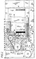
- the cash recycling ATM shown therein includes two picker/loader mechanisms 10 and 12 in accordance with the invention respectively associated with two currency cassettes 14 and 16.
- the cassette 14 is arranged to have currency notes of a first denomination loaded into it and picked therefrom
- the cassette 16 is arranged to have currency notes of a second denomination, different from the first denomination, loaded into it and picked therefrom.
- the picker/loader mechanisms 10 and 12 have two gates 17 and 18 respectively associated therewith. Each of the gates 17 and 18 is selectively movable between a loading position shown in solid outline in Fig. 1 and a picking position shown in chain outline in Fig. 1 under the control of electronic control means 19 (Fig. 12) included in the ATM.
- a user of the ATM can request the ATM to accept a cash deposit or to dispense cash.
- the user inserts a user identifying card into the ATM, and enters on the keyboard control means 20 his personal identification number and the quantity of cash to be paid in or to be withdrawn. If a cash deposit mode of operation is requested, then the user deposits one or more currency notes of one or both of said first and second denominations into a note deposit slot (not shown) from where they are fed to note picker means 22.
- deposited notes are fed along an entry feed path 24 via a multiple note detect means 26 for detecting the passage of multiple superposed sheets, via condition detect means 28 for determining whether each of the deposited notes is of acceptable condition, and via validator and denomination detect means 30 for determining whether each of the deposited notes is genuine and for determining the denomination of each genuine deposited note. If a deposited note is rejected by any of the above-mentioned means 26, 28 and 30, then the gates 17 and 18 are set to the picking position show in chain outline in Fig. 1. Also, a further gate 32 is set to a reject position shown in chain outline in Fig. 1, the gate 32 being settable between the reject position and a stacking position shown in solid outline under the control of the electronic control means 19(Fig. 12).
- the rejected note is then fed along a rejected note feed path 34 and returned to the customer at a rejected note exit slot (not shown). If a deposited note is accepted after having passed through the multiple note detect means 26, the condition detect means 28 and the validator and denomination detect means 30, then in a manner which will be described later the accepted note is loaded into the appropriate one of the cassettes 14 and 16 by the associated picker/loader mechanism 10 or 12, the associated gate 17 or 18 having previously been set to its loading position.
- the gates 17 and 18 are set to the picking positions shown in chain outline and the gate 32 is set to the note stacking position shown in solid outline.
- an appropriate number of currency notes are picked in conventional manner from one or both of the cassettes 14 and 16 by the associated picker/loader mechanism(s) 10 and/or 12.
- the picked notes are fed via multiple note detect means 35 to conventional stacker means 36 where the notes Are formed into a stack.
- the stack of notes is fed along an output feed path 38 to an exit slot (not shown) for collection by the user. If the multiple note detect means 35 detect the passage of multiple superposed notes, then, instead of being fed to the user, the stack of notes is fed from the stacker means 36 into a purge bin 40.
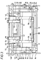
- the cassette 14 is of a type which is well known in the art, the cassette 14 including a floor member 42 for supporting corresponding long edges of a stack of currency notes 44 housed in the cassette 14, and a pusher plate 46 (Fig. 2) which is slidably mounted on the floor member 42 and which is arranged to urge the stack of notes 44 under the action of spring means (not shown) towards a stop member 47 positioned adjacent the front end 48 of the cassette 14.
- an opening 50 through which notes are withdrawn one by one in conventional manner by the picker/loader mechanism 12 during a cash withdrawal operation involving the dispensing of notes from the cassette 14.
- the opening 50 is closed by a flexible shutter 52.
- the shutter 52 is removed from the opening 50 to a position beneath the floor member 42 under the action of key pins 54 provided on a support member 56 for the cassette 14, the pins 54 engaging with projections 58 (Fig. 2) provided on the shutter 52. It should be understood that when the cassette 14 is removed from the ATM the shutter 52 is automatically returned to its closed position by spring means (not shown).
- the cassette 14 is arranged to be removably mounted on the support member 56.
- the side walls 60 of the cassette 14 are respectively provided with horizontally extending ridge members 62 and, as seen in Figs. 3 and 4, the cassette 14 is supported by the support member 56 by virtue of each of the ridge members 62 slidably engaging between a pair of horizontally extending guide bars 64 provided on an adjacent side wall 66 of the support member 56.
- the above-mentioned modification of the cassette 14 involves the provision of a second flexible shutter 68.
- the shutter 68 serves to close an opening 70 (see Fig. 6) formed in a lockable lid 72 of the cassette 14, the opening 70 extending into the upper half of the front end 48 of the cassette 14.
- the shutter 68 is removed from the opening 70 to a position beneath the lid 72.
- the shutter 68 is provided with a rigid rearward extension 74 (Fig.
- the support member 56 is slidably mounted between side walls 80 of a supporting framework 82 of the ATM by bearing means 84, the support member 56 being movable in a horizontal direction forwardly (i.e. from right to left with reference to Fig. 2) or rearwardly relative to the framework 82.
- a rack member 86 is secured to the underside of the support member 56, the rack member engaging with a pinion 88 secured on a drive shaft 90 rotatably mounted on the framework 82.
- the shaft 90 is driven by a stepping motor 92 (Fig. 12) controlled by the electronic control means 19.
- Deposited notes are fed to the picker/loader mechanisms 10 and 12 along the input feed path 24 (Fig. 1) by a transport mechanism 94 including feed belts 96,98 and 100 which pass around pulleys 102 as shown in Fig. 2.
- the transport mechanism 94 is driven by a main drive motor 96 (Fig. 12).
- the picker/loader mechanism 10 includes drive pulley means 104 secured on a drive shaft 106 driven by the main drive motor 96.
- a first plurality of feed belts 108 pass around, and are driven by, the pulley means 104, the belts 108 being spaced apart along the axis of the shaft 106 and also passing around associated pulley means 110.
- a second plurality of feed belts 112 also pass around, and are driven by, the pulley means 104, the belts 112 being interspersed with respect to the belts 108 and passing around associated pulley means 114.
- the belts 108 and 112 are continuously driven during operation of the picker/loader mechanism 10.
- the loading portion of the picker/loader mechanism 10 includes two feed belts 116 which are mounted in cooperative relationship with respect to two further feed belts 118.
- the belts 116 pass around pairs of pulleys 120 and 122, while the belts 118 pass around further pairs of pulleys 124, 126, and 128 and over parts of the peripheries of the pulleys 120 and a further pair of pulleys 130.
- the pulleys 120, 124, 126 and 128 are rotatably mounted with respect to the side walls 80 of the framework 82, while the pulleys 122 and 128 are rotatably mounted with respect to side walls 131 of a further supporting framework 132 which is positioned between, and secured to, the side walls 80. It should be understood that, when the cassette 14 is mounted in an operational picking or loading position relative to the picker/loader mechanism 10, the framework 132 projects into the interior of the cassette 14 through the opening 70 with the pulleys 122 and 128 disposed inside the cassette 14.
- the pulleys 120 and 124 are intermittently driven by a stepping motor 133 (Fig.
- the loading portion of the picker/loader mechanism 10 also includes two cylindrical holders 134 each of which serves as a housing for a respective flexible metal tape 136.
- Each tape 136 is housed in coiled manner in the respective holder 134 with a free end of the tape 136 projecting vertically downwards from the holder 134 through a slot 138 (Fig. 3) formed in the periphery of the holder 134.
- the holders 134 are mounted on a shaft 140 to which are secured the pulleys 120, the holders 134 being mounted so that they are held in a fixed position while permitting rotation of the shaft 140 relative to the holders 134.
- Each tape 136 is arranged to be driven by a drive mechanism incorporating a gear wheel 142 rotatably mounted on the shaft 140.
- Each gear wheel 142 is driven by a gear wheel 144 (Fig. 2) which in turn is driven by a stepping motor 146 (Fig. 12).
- the tapes 136 may be driven between a first position in which the free ends of the tapes 136 are in an extended lowermost position as shown in Figs.
- the tapes 136 are set to be in said first position when the picker/loader mechanism 10 is in a loading mode of operation, and are set to be in said second position when the mechanism 10 is in a picking mode of operation.
- a currency note fed by the feed mechanism 94 to the picker/loader mechanism 10 for loading into the cassette 14 is first gripped between the belt means 96 and the belts 108 and 112 passing around the pulley means 104, and is then diverted into the mechanism 10 by the associated gate 17 which is set to its loading position as shown in Fig. 2. After being diverted by the gate 17, the leading edge of the note is sensed by optical sensing means 148 and shortly thereafter the note is gripped between the belts 112 and cooperating roller means 150. The note is fed by the belts 112 and roller means 150 over guide means 152 to the entry nip of the belts 116 and 118. A tube 154 connected to an air pump (not shown) is positioned beneath the guide means 152.
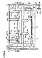
- the picking portion of the picker/loader mechanism 10 includes a tubular member 156 which extends between, and is rotatably mounted with respect to, the side walls 80.
- Two conventional pick arms 158 are secured on the tubular member 156, each pick arm 158 communicating with the interior of the tubular member 156.
- One end of the tubular member 156 projects beyond the corresponding side wall 80 and is connected by connection means (not shown) to a source of reduced pressure.
- the pick arms 158 are caused to undergo an oscillatory pivotal movement in conventional manner.
- cam roll means 162 are secured on a drive shaft 164 in cooperative relationship with respect to the belt means 108, the periphery of the cam roll means 162 comprising a high portion 166 and a low portion 168.
- the first currency note of the stack of notes 44 in the cassette 14 is engaged by the suction pads 160 of the pick arms 158.
- the lower long edge of this note is then pulled partly out of the cassette 14 through the opening 50, under the action of suction applied by the pick arms 158, and is fed between the low portion 168 of the cam roll means 162 and the belts 108 as the arms 158 are pivoted in a clockwise direction with reference to Fig. 5.
- This note is thereafter pulled completely out of the cassette 14 by virtue of being gripped between the belts 108 and the high portion 166 of the cam roll means 162 with the note being fed between guide means 170 and the belts 108.
- the note is then gripped and fed by the belts 108 and cooperating roller means 172, and is fed out of the picker/loader mechanism 10 by the feed mechanism 94 in cooperation with the belts 108 and 112, the gate 17 having previously been set to the picking position shown in Fig. 5.
- the picked note is fed to the stacker means 36 (Fig. 1).
- a timing disc 174 is mounted on the shaft 106 on which are secured the pulley means 104, the shaft 176 being driven by the main drive motor 96.
- the timing disc 174 is operatively associated with a sensor 178. In operation of the picker/loader mechanism 10, the sensor 178 applies a series of timing pulses to the electronic control means 19.
- the picker/loader mechanism 10 includes a lower pair of note retaining pawls 180 and an upper pair of note retaining pawls 182, the pawls 180 and 182 being located inside the cassette 14 when the cassette 14 is mounted in its operational picking or loading position relative to the mechanism 10.
- the lower pawls 180 are respectively provided at corresponding ends of a pair of arms 184 the other ends of which are secured on a shaft 186 which is rotatably mounted with respect to the side walls 80 and which is driven by a stepping motor 188 (Fig. 12).
- the arms 184 extend into the cassette 14 through the opening 50 and above the shutter 52, with the pawls 180 extending into or passing through slots 190 (see Fig. 6) formed in the floor member 42 of the cassette 14.
- the pawls 180 are movable between the non-operative position shown in Fig. 5 in which the pawls 180 are positioned below the upper surface of the floor member 42, and the operative position shown in Fig. 6 in which the pawls 180 are positioned above the upper surface of the floor member 42.
- the upper pawls 182 are secured on a shaft 192 which extends between, and is rotatably mounted with respect to, the side walls 131 of the framework 132.
- a toothed pulley 194 (Fig. 4) is secured on the shaft 192, while the pulleys 128 associated with the belts 118 are rotatably mounted on the shaft 192.
- An endless toothed belt 196 passes around the pulley 194 and also around toothed pulleys 198 and 200 and partly over the periphery of a pulley 202.
- the pulley 198 is secured on a drive shaft 204 which extends between, and is rotatably mounted with respect to, the side walls 80, the drive shaft 204 being driven by a stepping motor 206 (Fig. 12).
- the pawls 182 are pivotable between the operative position shown in Figs. 2 and 6 in which the pawls 182 extend below the upper front edge of the stack of notes 44, and the non-operative position shown in Fig. 5 in which the pawls 182 are positioned above the stack of notes 44.
- the electronic control means 19 energizes the main drive motor 96 so as to cause the transport mechanism 94, the feed belts 108 and 112 and associated roller means 150 and 172, and the cam roll means 162 to commence operation.
- the sensor 178 associated with the timing disc 174 commences to apply timing pulses to the electronic control means 19.
- Fig. 5 there will first be described the operation of the picker/loader mechanism 10 during a picking mode of operation forming part of a cash withdrawal operation, it being assumed that a plurality of notes will be picked from the stack of notes 44 in the cassette 14 and fed by the transport mechanism 94 to the stacker means 36.
- the gate 17 Prior to the picking operation commencing, under the control of the electronic control means 19, the gate 17 is set to the picking position shown in Fig. 5, the pawls 180 are set by the motor 188 to their non-operative position beneath the upper surface of the floor member 42, the pawls 182 are set by the motor 206 to the non-operative position shown in Fig.
- notes may also be picked from the cassette 16 by the associated picker/loader mechanism 12 for feeding to the stacker means 36, operation of the picker/loader mechanism 12 taking place before or after the operation of the picker/loader mechanism 10.
- a loading operation of the picker/loader mechanism 10 forming part of a cash deposit operation of the ATM, is to take place subsequent to a picking operation, then the following events take place prior to the loading operation commencing.
- the assembly of the support member 56 and the cassette 14 is moved by the motor 92 via the pinion 88 and the rack member 86 from left to right with reference to Fig. 2 from the leftmost position shown in Fig. 2 to the rightmost position shown in Fig. 6.
- the pawls 180 and 182 are then moved to the operative positions shown in Fig. 6 in which they are positioned in front of the stack of notes 44.
- the assembly of the support member 56 and the cassette 14 is then moved by the motor 92 back to the position shown in Fig. 2.
- the front note in the stack of notes 44 is engaged and stopped by the pawls 180 and 182 as shown in Fig. 2, with the pawls 180 engaging the lower front edge of the stack 44 and the pawls 182 engaging the upper front edge of the stack 44.
- the steel tapes 136 are then moved by the motor 146 to their extended position in which the free ends of the tapes 136 are positioned a short distance above the floor member 42.
- the loading of a plurality of notes into the cassette 14 by the picker/loader mechanism 10 involves feeding the notes one by one to the entry nip of the belts 116 and 118 in the manner previously described, with the long edges of the notes being perpendicular to the feed path.
- the sensing means 148 in response to the sensing of the leading edge of the first note 44 fed into the picker/loader mechanism 10, the sensing means 148 sends a signal to the electronic control means 19.
- the electronic control means 19 starts the stepping motor 133 so as to cause the feed belts 116 and 118 to commence operation, such operation commencing prior to the leading edge of the first note 441 reaching the nip of the feed belts 116 and 118.
- the spacing between the pulleys 120 and the roller means 150 is such that, when the leading edge of the first note 441 reaches the nip of the feed belts 116 and 118 and becomes gripped thereby, the trailing edge of the note 441 is still gripped between the belts 112 and the roller means 150, as shown in Fig. 7. It should be understood that, upon a leading portion of the note 441 being gripped and driven by the belts 116 and 118, this portion is bent over part of the periphery of each of the pulleys 120, so that this portion is deflected away from the feed path defined by the cooperating feed belts 112 and roller means 150.
- the belts 112 and roller means 150 driven by the motor 96, operate continuously during operation of the picker/loader mechanism 10.
- the next note 4411 is fed by the belts 112 and roller means 150 towards the nip of the belts 116 and 118.
- the leading edge of the second note 4411 is sensed by the sensing means 148, in response to which a signal is sent by the sensing means 148 to the electronic control means 19.
- the electronic control means 19 starts the stepping motor 133 so as to cause the belts 116 and 118 to recommence operation, this recommencement of operation occurring prior to the leading edge of the second note 441 reaching the nip of the belts 116 and 118.
- the leading edge of the second note 4411 moves beneath the trailing portion of the first note 441 so that a leading portion of the note 4411 is positioned in overlapping relationship with respect to the note 441.
- the two notes 441 and 4411 are fed together, in overlapping relationship, partly around the peripheries of the pulleys 120, as shown in Fig. 9.
- a stream of overlapping notes are fed by the belts 116 and 118 along a feed path defined by the belts 116 and 118 and by the steel tapes 136 until the leading edges of the notes abut against the floor member 42 of the currency cassette 14.
- currency notes are fed into the cassette 14 and formed into a stack between the steel tapes 136 and the pawls 180 and 182 as shown in Fig. 11, with corresponding long edges of the notes in this stack being supported by the floor member 42 and with one side of this stack being supported by the steel tapes 136.
- a stack of up to 20 notes can be loaded into the cassette 14 into the space 208 between the steel tapes 136 and the pawls 180 and 182. If it is desired to load more than 20 notes into the cassette 14, then after 20 notes have been fed to the picker/loader mechanism 10, the transport mechanism 94 is stopped, the pawls 180 and 182 are moved to their non-operative positions, and the steel tapes 136 are moved to their retracted position. This enables the stack of notes 44 present in the cassette 14 prior to the commencement of the loading operation to be combined with the newly loaded notes, the pusher plate 46 pushing the combined stacks against the stop member 47.
- a further space 208 for accommodating a further stack of loaded notes is then created by moving the assembly of the support member 56 and the cassette 14 to its rightmost position, moving the pawls 180 and 182 to their operative positions, and returning said assembly to its leftmost position, the steel tapes 136 then being returned to their extended position. This procedure may be repeated as many times as may be necessary, or until the cassette 14 is full.
- the gate 17 is set to its picking position, the steel tapes 136 are set to their retracted position, and the pawls 180 and 182 are set to their non-operative positions, thereby enabling the pusher plate 46 to push the stack of notes 44 into engagement with the stop member 47.
- the cassette 14 is provided with sensing means (not shown) for providing a signal to the electronic control means 19 if the number of notes in the cassette 14 reaches a predetermined low level or a predetermined high level. Upon receipt of such signal, the electronic control means 19 causes the generation of a warning signal indicative that removal of the cassette 14 from the picker/loader mechanism 10 is required.
- the cassette 14 is removed by sliding it rearwardly out of the support structure 56 and it is then replaced by a partially filled cassette, enabling the picker/loader mechanism 10 to recommence operation in either a picking or a loading mode.
- the picker/loader mechanism 10 described above has the advantages that it is of simple construction and is simple to operate, and also is reliable in operation.
Landscapes
- Physics & Mathematics (AREA)
- General Physics & Mathematics (AREA)
- Engineering & Computer Science (AREA)
- Mechanical Engineering (AREA)
- Sheets, Magazines, And Separation Thereof (AREA)
Claims (10)
- Un appareil de manipulation de feuilles opérable en mode de chargement et en mode de prise, et comportant un récipient (14), un moyen de chargement (112, 116, 118, 150) pour charger des feuilles dans ledit récipient (14) lorsque ledit appareil est dans ledit mode de chargement, un moyen de prise (158, 162) pour prendre des feuilles une par une dans ledit récipient lorsque ledit appareil est dans ledit mode de prise, des moyens de retenue de pile amovible (180, 182), et un premier moyen d'actionnement (184, 188; 196, 206) arrangé pour faire passer lesdits moyens de retenue entre des positions opérante et non opérante, ledit récipient étant arrangé pour contenir une pile de feuilles (44) et comportant un élément pousseur (46) arrangé, lorsque ledit appareil est dans ledit mode de prise, pour inciter ladite pile d'une manière élastique contre un élément butée (47) prévu dans ledit récipient et arrangé, lorsque ledit appareil est dans ledit mode de chargement, pour inciter ladite pile (44) contre lesdits moyens de retenue, un espace (208) ayant été créé entre ladite pile et ledit élément butée (47) pour accommoder une pluralité de feuilles en plus de ladite pile, caractérisé par un élément de support amovible (56) sur lequel ledit récipient (14) est monté lors du fonctionnement, un deuxième moyen d'actionnement (88, 92) arrangé pour faire passer ledit élément de support ainsi que ledit récipient entre une position opérante dans laquelle le chargement ou la prise a lieu et une position non opérante, et un moyen de contrôle (19) arrangé pour contrôler le fonctionnement desdits premier et deuxième moyens d'actionnement par quoi, lorsque ledit élément de support (56) est dans ladite position opérante, lesdits moyens de retenue de pile (180, 182) sont dans leur position non opérante en mode de prise et sont dans leur position opérante en mode de chargement, et par quoi, lorsque ledit appreil passe d'un mode de prise à un mode de chargement, ledit élément de support (56) est mis dans sa position non opérante et lesdits moyens de retenue (180, 182) sont mis dans leur position opérante après quoi ledit élément de support est mis dans sa position opérante, créant ainsi ledit espace (208).
- Un appareil conformément à la revendication 1, caractérisé en ce que ledit récipient (14) est monté de façon à pouvoir être enlevé sur ledit élément de support (56) et comporte une enceinte (60, 72) pour ladite pile, ladite enceinte étant dotée de première et deuxième ouvertures (50, 70) qui sont respectivement fermables par des premier et deuxième volets (52, 68), et ledit appareil étant doté de moyens (54, 78) pour provoquer l'ouverture automatique desdits volets lorsque ledit récipient est monté sur ledit élément de support (56), des parties (158; 122, 128) dudit moyen de prise et dudit moyen de chargement passant dans l'intérieur dudit récipient (14) à travers lesdites première et deuxième ouvertures (50, 70) respectivement lorsque ledit récipient (14) est monté sur ledit élément de support (56).
- Un appareil conformément à la revendication 1 ou à la revendication 2, caractérisé en ce que lesdits moyens de retenue de pile comprennent un moyen de retenue inférieur (180) pouvant être déplacé entre des positions opérante et non opérante et arrangé pour engager un bord d'extrémité inférieure de ladite pile (44) lorsqu'il est dans sa position opérante, et un moyen de retenue supérieur (182) pouvant être déplacé entre des positions opérante et non opérante et arrangé pour engager un bord d'extrémité supérieure de ladite pile lorsqu'il est dans sa position opérante.
- Un appareil conformément à la revendication 3, caractérisé en ce que lesdits moyens de retenue inférieur et supérieur sont respectivement formés par des moyens cliquets inférieur et supérieur pouvant être déplacés par pivotement (180, 182).
- Un appareil conformément aux revendications 2 et 3, caractérisé en ce que ledit moyen de retenue inférieur (180) et ledit moyen de retenue supérieur (182) sont positionnés de façon à passer dans l'intérieur dudit récipient (14) à travers lesdites première et deuxième ouvertures (50, 70) respectivement lorsque ledit récipient est monté sur ledit élément de support (56).
- Un appareil conformément à l'une quelconque des revendications précédentes, caractérisé par un moyen de support de feuilles (136) pouvant être déplacé sous le contrôle dudit moyen de contrôle (19) entre des première et deuxième positions, ledit moyen de support de feuilles étant arrangé pour être dans ladite première position dans laquelle ledit moyen de support de feuilles s'étend dans ledit espace (208) lorsque ledit appareil est dans ledit mode de chargement, et étant arrangé pour être dans ladite deuxième position dans laquelle ledit moyen de support de feuilles est rentré hors dudit espace lorsque ledit appareil est dans ledit mode de prise.
- Un appareil conformément à la revendication 6, caractérisé en ce que ledit moyen de support de feuilles est formé par un moyen ruban en métal flexible (136).
- Un appareil conformément à la revendication 7, caractérisé par un moyen support (134) pour abriter ledit moyen ruban (136) de manière enroulée, et un moyen d'actionnement (144, 146) pour faire entrer dans ledit espace (208) et sortir de ce dernier une partie extrémité libre dudit moyen ruban.
- Un appareil conformément à l'une quelconque des revendications précédentes, caractérisé en ce que ledit moyen de chargement comporte un premier moyen d'acheminement (112, 150) arrangé pour acheminer d'une manière continue pendant une opération de chargement une pluralité de feuilles une par une dans un rapport espacé les unes par rapport aux autres le long d'une première voie d'acheminement à un deuxième moyen d'acheminement (116, 118) arrangé pour acheminer ladite pluralité de feuilles le long d'une deuxième voie d'acheminement, la partie avant d'une feuille, au début, lorsqu'elle est engagée et entraînée par ledit deuxième moyen d'acheminement, étant déviée de ladite première voie d'acheminement par quoi une partie arrière de chaque feuille lorsqu'elle quitte ledit premier moyen d'acheminement (112, 150) est déviée de ladite première voie d'acheminement, ledit moyen de contrôle (19) étant arrangé pour contrôler le fonctionnement dudit deuxième moyen d'acheminement (116, 118) par quoi, suite à l'engagement d'une feuille par ledit deuxième moyen d'acheminement et suite à la déviation d'une partie arrière de cette feuille par rapport à ladite première voie d'acheminement, le fonctionnement dudit deuxième moyen d'acheminement est arrêté jusqu'à ce que le bord avant de la feuille suivante soit positionné dans un rapport chevauchant par rapport à la feuille qui vient tout de suite avant, après quoi ledit deuxième moyen d'acheminement est remis en marche, ledit deuxième moyen d'acheminement (116, 118) servant, sous le contrôle dudit moyen de contrôle (19), à faire acheminer ladite pluralité de feuilles d'une manière chevauchante le long de ladite deuxième voie d'acheminement dans ledit espace (208).
- Un appareil conformément à la revendication 9, caractérisé par un moyen capteur (148) positionné en amont dudit deuxième moyen d'acheminement (116, 118) et arrangé pour envoyer un signal audit moyen de contrôle (19) en réponse au comptage par ledit moyen capteur d'un bord d'une feuille acheminée par ledit premier moyen d'acheminement (112, 150), ledit moyen de contrôle étant arrangé pour provoquer la mise en marche dudit deuxième moyen d'acheminement (116, 118) un certain temps prédéterminé après la réception dudit signal par ledit moyen de contrôle.
Applications Claiming Priority (2)
| Application Number | Priority Date | Filing Date | Title |
|---|---|---|---|
| GB9216806 | 1992-08-07 | ||
| GB929216806A GB9216806D0 (en) | 1992-08-07 | 1992-08-07 | Apparatus for loading and picking sheets |
Publications (3)
| Publication Number | Publication Date |
|---|---|
| EP0582473A2 EP0582473A2 (fr) | 1994-02-09 |
| EP0582473A3 EP0582473A3 (fr) | 1994-02-23 |
| EP0582473B1 true EP0582473B1 (fr) | 1996-02-07 |
Family
ID=10720000
Family Applications (1)
| Application Number | Title | Priority Date | Filing Date |
|---|---|---|---|
| EP93306171A Expired - Lifetime EP0582473B1 (fr) | 1992-08-07 | 1993-08-04 | Dispositif de chargement et de prise de feuilles |
Country Status (4)
| Country | Link |
|---|---|
| US (1) | US5271613A (fr) |
| EP (1) | EP0582473B1 (fr) |
| DE (1) | DE69301510T2 (fr) |
| GB (1) | GB9216806D0 (fr) |
Families Citing this family (23)
| Publication number | Priority date | Publication date | Assignee | Title |
|---|---|---|---|---|
| US5357314A (en) * | 1992-01-29 | 1994-10-18 | Fuji Photo Film Co., Ltd. | Film accumulator and film accumulator/holder |
| AU673262B2 (en) * | 1993-05-13 | 1996-10-31 | Kabushiki Kaisha Ace Denken | Amusement media dispensing machine, for which notes can be used |
| DE4408981C1 (de) * | 1994-03-16 | 1995-06-22 | Siemens Nixdorf Inf Syst | Ausgabeeinheit für Wertscheine |
| JP3368347B2 (ja) * | 1994-03-29 | 2003-01-20 | オムロン株式会社 | 紙葉類収納装置および取引処理装置 |
| GB9525767D0 (en) | 1995-12-16 | 1996-02-14 | At & T Global Inf Solution | Apparatus for detecting multiple superposed sheets |
| US5871209A (en) * | 1996-03-01 | 1999-02-16 | Currency Systems International, Inc. | Cassette based document handling system |
| US5996314A (en) * | 1996-05-22 | 1999-12-07 | Currency Systems International, Inc. | Currency strapping machine |
| GB9623046D0 (en) * | 1996-11-06 | 1997-01-08 | Ncr Int Inc | Escrow storage device |
| JP2002502531A (ja) * | 1997-05-30 | 2002-01-22 | キャピタル セキュリティー システムズ インコーポレイション | 自動書類キャッシングシステム |
| US5987439A (en) * | 1997-05-30 | 1999-11-16 | Capital Security Systems, Inc. | Automated banking system for making change on a card or user account |
| US6012048A (en) * | 1997-05-30 | 2000-01-04 | Capital Security Systems, Inc. | Automated banking system for dispensing money orders, wire transfer and bill payment |
| US7653600B2 (en) * | 1997-05-30 | 2010-01-26 | Capital Security Systems, Inc. | Automated document cashing system |
| US5897625A (en) * | 1997-05-30 | 1999-04-27 | Capital Security Systems, Inc. | Automated document cashing system |
| US6264556B1 (en) * | 1997-10-29 | 2001-07-24 | Japan Cash Machine Co., Ltd. | Gaming machine having note hopper/dispenser |
| GB2364591A (en) * | 2000-07-07 | 2002-01-30 | Ncr Int Inc | Self service terminal with an escrow unit |
| US6742644B1 (en) * | 2000-11-27 | 2004-06-01 | Jcm American Corporation | Note acceptor-dispenser validator |
| US20060293783A1 (en) * | 2005-06-02 | 2006-12-28 | Peter Hand | Intelligent cash control system |
| DE102008018935A1 (de) * | 2008-04-15 | 2009-10-22 | Wincor Nixdorf International Gmbh | Einzelblatthandhabungsvorrichtung zur Eingabe und zur Ausgabe von rechteckigen Einzelblättern, insbesondere von Banknoten, in einen bzw. aus einem Behälter |
| DE102008018961A1 (de) * | 2008-04-15 | 2009-10-29 | Wincor Nixdorf International Gmbh | Einzelblatthandhabungsvorrichtung zur Eingabe von rechteckigen Einzelblättern in einen Behälter |
| US8393609B2 (en) | 2009-02-02 | 2013-03-12 | Japan Cash Machine Co., Ltd. | Document handler |
| DE102009058519A1 (de) * | 2009-12-16 | 2011-06-22 | WINCOR NIXDORF International GmbH, 33106 | Vorrichtung zur Handhabung von Wertscheinen |
| TWI425448B (zh) * | 2010-02-02 | 2014-02-01 | Nippon Kinsen Kikai Kk | 紙張類處理裝置 |
| US11263874B1 (en) * | 2021-07-06 | 2022-03-01 | Nautilus Hyosung America, Inc. | Cash cassette note separation technique |
Citations (1)
| Publication number | Priority date | Publication date | Assignee | Title |
|---|---|---|---|---|
| US4510380A (en) * | 1981-06-19 | 1985-04-09 | Laurel Bank Machine Co., Ltd. | Automatic money receiving and disbursing machine |
Family Cites Families (11)
| Publication number | Priority date | Publication date | Assignee | Title |
|---|---|---|---|---|
| US2210258A (en) * | 1938-08-24 | 1940-08-06 | Chandler & Price Co | Sheet feeding mechanism for printing presses |
| JPS5839391A (ja) * | 1981-08-31 | 1983-03-08 | ロ−レルバンクマシン株式会社 | 自動入出金機における入出金機構 |
| GB2108935B (en) * | 1981-11-10 | 1985-06-12 | Ncr Co | Sheet handling apparatus |
| JPS58135043A (ja) * | 1982-02-04 | 1983-08-11 | Laurel Bank Mach Co Ltd | 自動入出金機における紙幣分離送出機構 |
| US4980543A (en) * | 1983-01-26 | 1990-12-25 | Tokyo Shibaura Denki Kabushiki Kaisha | Multiple denominator bank note depositor/dispenser with automatic loading to and from storage section |
| JPS59136886A (ja) * | 1983-01-26 | 1984-08-06 | 株式会社東芝 | 自動取引装置 |
| JPS63218440A (ja) * | 1987-03-06 | 1988-09-12 | Nec Corp | リサイクル収納繰出し機構 |
| JPH0721832B2 (ja) * | 1987-11-20 | 1995-03-08 | インタ−ナシヨナル・ビジネス・マシ−ンズ・コ−ポレ−シヨン | 紙幣処理装置 |
| JPH01242360A (ja) * | 1988-03-18 | 1989-09-27 | Hitachi Ltd | 紙葉類堆積繰出し機構 |
| JP2667739B2 (ja) * | 1990-08-16 | 1997-10-27 | 沖電気工業株式会社 | 紙幣自動入出金装置 |
| GB9018078D0 (en) * | 1990-08-17 | 1990-10-03 | Ncr Co | Sheet handling apparatus |
-
1992
- 1992-08-07 GB GB929216806A patent/GB9216806D0/en active Pending
- 1992-12-22 US US07/995,245 patent/US5271613A/en not_active Expired - Lifetime
-
1993
- 1993-08-04 DE DE69301510T patent/DE69301510T2/de not_active Expired - Fee Related
- 1993-08-04 EP EP93306171A patent/EP0582473B1/fr not_active Expired - Lifetime
Patent Citations (1)
| Publication number | Priority date | Publication date | Assignee | Title |
|---|---|---|---|---|
| US4510380A (en) * | 1981-06-19 | 1985-04-09 | Laurel Bank Machine Co., Ltd. | Automatic money receiving and disbursing machine |
Also Published As
| Publication number | Publication date |
|---|---|
| US5271613A (en) | 1993-12-21 |
| DE69301510D1 (de) | 1996-03-21 |
| GB9216806D0 (en) | 1992-09-23 |
| EP0582473A2 (fr) | 1994-02-09 |
| EP0582473A3 (fr) | 1994-02-23 |
| DE69301510T2 (de) | 1996-08-29 |
Similar Documents
| Publication | Publication Date | Title |
|---|---|---|
| EP0582473B1 (fr) | Dispositif de chargement et de prise de feuilles | |
| JP4497575B2 (ja) | 紙葉収納払出装置 | |
| US6352254B1 (en) | Paper sheet manipulating apparatus and paper sheet transaction apparatus | |
| US5597996A (en) | Cash dispensing apparatus (ATM) and method for separating rejected bank notes | |
| JPH028341B2 (fr) | ||
| US6334610B1 (en) | Leaf transfer mechanism unit | |
| EP0565254B1 (fr) | Appareil pour charger des feuilles dans un réceptacle | |
| US5110105A (en) | Sheet handling apparatus | |
| JP3192973B2 (ja) | 紙幣入出金装置 | |
| JPH039514B2 (fr) | ||
| JP3217232B2 (ja) | 自動取引装置 | |
| KR100227403B1 (ko) | 지폐 입출금 장치 및 지폐 집적기구 | |
| JPS6323099B2 (fr) | ||
| JPH0139145B2 (fr) | ||
| JPS5943739A (ja) | 紙葉類収納箱 | |
| JP4089021B2 (ja) | 自動取引装置 | |
| JPH10310334A (ja) | 媒体収納繰出し装置 | |
| JPS59142692A (ja) | 紙幣取扱装置 | |
| JP3328527B2 (ja) | 自動取引装置 | |
| JP2609693B2 (ja) | 紙葉類収納装置 | |
| JPS5943753A (ja) | 紙葉類取扱装置 | |
| JPH07149463A (ja) | 紙幣入出金装置 | |
| JP3490199B2 (ja) | 紙幣出金機 | |
| JP2600701Y2 (ja) | 貨幣入出金機 | |
| JP2597755B2 (ja) | 紙幣入出金装置 |
Legal Events
| Date | Code | Title | Description |
|---|---|---|---|
| PUAI | Public reference made under article 153(3) epc to a published international application that has entered the european phase |
Free format text: ORIGINAL CODE: 0009012 |
|
| PUAL | Search report despatched |
Free format text: ORIGINAL CODE: 0009013 |
|
| AK | Designated contracting states |
Kind code of ref document: A2 Designated state(s): DE FR GB |
|
| AK | Designated contracting states |
Kind code of ref document: A3 Designated state(s): DE FR GB |
|
| 17P | Request for examination filed |
Effective date: 19940816 |
|
| RAP1 | Party data changed (applicant data changed or rights of an application transferred) |
Owner name: AT&T GLOBAL INFORMATION SOLUTIONS INTERNATIONAL IN |
|
| 17Q | First examination report despatched |
Effective date: 19950711 |
|
| GRAA | (expected) grant |
Free format text: ORIGINAL CODE: 0009210 |
|
| AK | Designated contracting states |
Kind code of ref document: B1 Designated state(s): DE FR GB |
|
| REF | Corresponds to: |
Ref document number: 69301510 Country of ref document: DE Date of ref document: 19960321 |
|
| ET | Fr: translation filed | ||
| PLBE | No opposition filed within time limit |
Free format text: ORIGINAL CODE: 0009261 |
|
| STAA | Information on the status of an ep patent application or granted ep patent |
Free format text: STATUS: NO OPPOSITION FILED WITHIN TIME LIMIT |
|
| REG | Reference to a national code |
Ref country code: FR Ref legal event code: CD |
|
| 26N | No opposition filed | ||
| REG | Reference to a national code |
Ref country code: GB Ref legal event code: IF02 |
|
| PGFP | Annual fee paid to national office [announced via postgrant information from national office to epo] |
Ref country code: GB Payment date: 20030623 Year of fee payment: 11 |
|
| PGFP | Annual fee paid to national office [announced via postgrant information from national office to epo] |
Ref country code: DE Payment date: 20030918 Year of fee payment: 11 |
|
| REG | Reference to a national code |
Ref country code: FR Ref legal event code: D6 |
|
| PGFP | Annual fee paid to national office [announced via postgrant information from national office to epo] |
Ref country code: FR Payment date: 20040723 Year of fee payment: 12 |
|
| PG25 | Lapsed in a contracting state [announced via postgrant information from national office to epo] |
Ref country code: GB Free format text: LAPSE BECAUSE OF NON-PAYMENT OF DUE FEES Effective date: 20040804 |
|
| PG25 | Lapsed in a contracting state [announced via postgrant information from national office to epo] |
Ref country code: DE Free format text: LAPSE BECAUSE OF NON-PAYMENT OF DUE FEES Effective date: 20050301 |
|
| GBPC | Gb: european patent ceased through non-payment of renewal fee |
Effective date: 20040804 |
|
| PG25 | Lapsed in a contracting state [announced via postgrant information from national office to epo] |
Ref country code: FR Free format text: LAPSE BECAUSE OF NON-PAYMENT OF DUE FEES Effective date: 20060428 |
|
| REG | Reference to a national code |
Ref country code: FR Ref legal event code: ST Effective date: 20060428 |