EP0578238A1 - Arrangement de dispositif de sécurité - Google Patents
Arrangement de dispositif de sécurité Download PDFInfo
- Publication number
- EP0578238A1 EP0578238A1 EP93110895A EP93110895A EP0578238A1 EP 0578238 A1 EP0578238 A1 EP 0578238A1 EP 93110895 A EP93110895 A EP 93110895A EP 93110895 A EP93110895 A EP 93110895A EP 0578238 A1 EP0578238 A1 EP 0578238A1
- Authority
- EP
- European Patent Office
- Prior art keywords
- arrester
- latches
- car
- elevator
- frame
- Prior art date
- Legal status (The legal status is an assumption and is not a legal conclusion. Google has not performed a legal analysis and makes no representation as to the accuracy of the status listed.)
- Withdrawn
Links
Images


Classifications
-
- B—PERFORMING OPERATIONS; TRANSPORTING
- B66—HOISTING; LIFTING; HAULING
- B66B—ELEVATORS; ESCALATORS OR MOVING WALKWAYS
- B66B5/00—Applications of checking, fault-correcting, or safety devices in elevators
- B66B5/28—Buffer-stops for cars, cages, or skips
- B66B5/284—Buffer-stops for cars, cages, or skips mounted on cars or counterweights
-
- B—PERFORMING OPERATIONS; TRANSPORTING
- B66—HOISTING; LIFTING; HAULING
- B66B—ELEVATORS; ESCALATORS OR MOVING WALKWAYS
- B66B17/00—Hoistway equipment
- B66B17/34—Safe lift clips; Keps
-
- B—PERFORMING OPERATIONS; TRANSPORTING
- B66—HOISTING; LIFTING; HAULING
- B66B—ELEVATORS; ESCALATORS OR MOVING WALKWAYS
- B66B5/00—Applications of checking, fault-correcting, or safety devices in elevators
- B66B5/02—Applications of checking, fault-correcting, or safety devices in elevators responsive to abnormal operating conditions
- B66B5/16—Braking or catch devices operating between cars, cages, or skips and fixed guide elements or surfaces in hoistway or well
- B66B5/26—Positively-acting devices, e.g. latches, knives
Definitions
- the present invention relates to a safety device arrangement for stopping the downward drift of an elevator car, as defined in the introductory part of claim 1.
- Direct-acting hydraulic elevators have generally been used for the transport of heavy goods, for which purpose they are well suited. Their rated loads are many times or even several tens of times higher than those of hydraulic passenger elevators. Direct-acting hydraulic elevators generally do not need a safety gear for the stopping of uncontrolled fall of the elevator car because the hydraulic cylinders are provided with throttles limiting the outflow of the hydraulic fluid so that the speed of the elevator car cannot exceed a safe value. Thus, the elevator car descends slowly along the shaft to the lowest position of its travel. The problem with these elevators is not the danger of the elevator car falling down, but a situation where the elevator car drifts slowly downwards from the door zone, so that the threshold between the floor of the elevator car and the landing floor becomes too high.
- a common case is one in which the hydraulic fluid for some reason gradually “leaks" out of the lifting cylinder, with the result that, if the elevator is not used for a long period, the car drifts downwards from the floor level.
- the elevator car is provided with arresters or other gripping devices designed to prevent the car from moving down from the floor level.
- arresters or other gripping devices designed to prevent the car from moving down from the floor level.
- These devices for preventing downward drift must be of a strong design as they have to withstand the possibly unevenly distributed strain imposed by the load and also the changes of load resulting from the loading or unloading of the car.
- arresters like this are rigidly fixed to the elevator car, their use for the stopping of the elevator from full speed cannot be considered a good solution because of the fairly high deceleration occurring in these cases.
- the safety device arrangement of the invention for stopping the downward drift of an elevator car is characterized by what is presented in claim 1.
- Advantageous embodiments of the invention are characterized by the features presented in the other claims.
- the invention provides e.g. the advantage that, when the elevator car rests on the latches of the arrester, the stress imposed by it on the latches is evenly distributed. Consequently, no special measures are required to start the elevator moving after being arrested by the latches. It only has to be moved up through some distance to release the latches.
- Another advantage is that, when the elevator is stopped from a normal travelling speed by means of the safety device arrangement, the deceleration is effected by means of buffers. The average deceleration is determined by the buffer stroke length corresponding to the momentary load and by the initial speed of the elevator car when arrested by the safety device arrangement. The instantaneous deceleration value depends especially on the characteristics of the buffer elements selected.
- a spring buffer provides progressive deceleration in relation to the stopping distance.
- a sufficient stopping distance in relation to the nominal speed of the the elevator is easily achieved by using buffer elements with a suitable free stoke length.
- the sliding guide shoes of the arrester eliminate the risk of the arrester slipping aside from under the car.
- the safety device arrangement of the invention can also be quite easily installed on elevators already in use. As the arrester comprised in the safety device arrangement contains a buffer function in itself, no separate buffers need to be installed at the bottom of the elevator shaft.
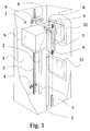
- Figure 1 shows a direct-acting hydraulic elevator for the transport of goods, in which the force of the hydraulic cylinders 2 imparting vertical motion to the elevator car 1 is applied to the car structures directly, not e.g. via hoisting ropes.
- the elevator car moves along guide rails 5 fixed with rail clamps 4 to the walls of the elevator shaft 3.
- the guide rails guide the elevator car by means of sliding guide shoes 6.
- the car frame 7 of this elevator comprises two lifting supports 8.
- the elevator car rests on the lifting supports on top of the lifting cylinders 2.
- the supporting force producing vertical motion of the car is generated by the lifting cylinders 2 and applied to the car via the lifting supports 8.
- the cabin 9 of the elevator car 1 is fitted inside the car frame 7.
- the elevator car and the landings are provided with doors 32.
- Figure 2 presents an arrester 10 mounted under an elevator car 1 (only the lower part of the car is shown in the figure).
- buffer elements 13 Placed between the frame beam 11 of the arrester and the bottom beam 12 of the car frame 7 are buffer elements 13.
- the buffer elements are attached by one end to the bottom beam 12 of the car frame and to the arrester frame 11 by the other end.
- the largest distance between the arrester and the car frame bottom beam is determined by binders 14 placed around the arrester, each of which consists of a flat iron bar 15 placed on top of the car frame bottom beam 12 and another flat iron bar 16 placed under the arrester and two tie bolts 17 connecting the flat iron bars on top of the car frame bottom beam and under the arrester, said bolts passing by the sides of the bottom beam 12 and the arrester 10, one bolt on each side.
- Each end of the arrester 10 is provided with a sliding guide shoe 18, mounted so that they follow the same guide rail 5 as the elevator guide shoes 6 on the corresponding side of the car 1.
- the sliding guide shoes 18 of the arrester prevent the latter from slipping from under the car frame, so the joint arrester between the arrester and the car frame need not be very rigid in the horizontal direction. This means that a relatively simple structure can be used to join the arrester and the car frame.
- the tongues of the guide rails are indicated by reference number 19.
- the arrester 10 has four latches 20, two on each side. The latches 20 on each side are actuated by means of lifting magnets 21 placed on the sides of the arrester.
- the spindle 22 of the lifting magnet turns an axle 23, which again turns the latch by means of a lever 24 either to a travel position or to an arrest position.
- the latches 20 of the arrester are shown in the arrest position and the elevator car 1 in a position where the latches have caught on stop blocks 26 provided in the wall 25 of the elevator shaft.
- all four latches of the arrester operate substantially simultaneously.
- the weight of the elevator car is substantially carried by the hydraulic cylinders 2, as is indicated by the fact that the buffer elements 13 are not much compressed and that there is no gap between the binders 14 and the arrester.
- the arrest position is the rest position of the latches 20, which return to this position even in the event of power failure.
- the return of the latches can be ensured by mounting a return spring (not shown in the figures) in conjunction with the lifting magnet, levers or latches.
- the latches of the arrester are in the travel position only when the elevator car is travelling. When the car sets off from a situation where it has been supported by the latches 20 on the stop blocks 26 in the shaft walls, it is preferable first to let the car run upwards through some distance and only then to turn the latches of the arrester into the travel position. To obtain an indication of whether the elevator car is resting on the latches, it is easy to provide the arrester with a suitable sensor, e.g. a switch placed between the arrester and the car frame. The drawings do not show a sensor.
- FIG. 3 shows the arrester 10 in end view.
- the frame of the arrester consists of three beams 27,28 joined together so that they form a frame with a cross-section resembling the letter H. Attached by their lower ends to the beam constituting the transverse part of the H-profile are the buffer elements 13, whose upper ends are fixed to the bottom beam structure 12 of the car frame. Placed at each end of the arrester frame is a plate 29 to which the sliding guide shoes 18 and the latch frames 30 are attached.
- the latches 20 are turnably mounted in the latch frames.
- the lever 24, joined by one end to a projection 31 provided on the axle 23, turns the latch about the latch joint, moving it to the arrest position or to the travel position, depending on the direction of the lever motion.
- the buffer elements 13 are placed inside the H-profile frame, it is generally unnecessary to provide the arrangement with a separate motion limiter to prevent buffer element compression exceeding the designed amount, but if desirable, e.g. when non-conventional buffer elements are used, it is possible to provide the arrester frame e.g. with flat-iron stoppers (not shown) of a suitable height, placed on top of the frame at either end.
- stop blocks could be attached to the guide rails or to the rail clamps instead of to the shaft walls.
- the lowest landing need not necessarily be provided with stop blocks for the latches, but this landing, or the bottom of the shaft, may be provided with a stopper designed to receive the frame beam or some other fixed part of the arrester.
- the safety device arrangement can also be applied to other types of elevator besides hydraulic elevators for goods transport. Instead of the separate buffer elements presented in the examples, it would be possible to use a rather large, compressible filler block of a continuous or nearly continuous structure, placed between the car frame and the arrester.
Applications Claiming Priority (2)
| Application Number | Priority Date | Filing Date | Title |
|---|---|---|---|
| FI923114A FI92812C (fi) | 1992-07-07 | 1992-07-07 | Turvalaitejärjestely |
| FI923114 | 1992-07-07 |
Publications (1)
| Publication Number | Publication Date |
|---|---|
| EP0578238A1 true EP0578238A1 (fr) | 1994-01-12 |
Family
ID=8535580
Family Applications (1)
| Application Number | Title | Priority Date | Filing Date |
|---|---|---|---|
| EP93110895A Withdrawn EP0578238A1 (fr) | 1992-07-07 | 1993-07-07 | Arrangement de dispositif de sécurité |
Country Status (8)
| Country | Link |
|---|---|
| US (1) | US5411117A (fr) |
| EP (1) | EP0578238A1 (fr) |
| JP (1) | JP2641382B2 (fr) |
| CN (1) | CN1034323C (fr) |
| AU (1) | AU661588B2 (fr) |
| BR (1) | BR9302787A (fr) |
| CA (1) | CA2099963C (fr) |
| FI (1) | FI92812C (fr) |
Cited By (9)
| Publication number | Priority date | Publication date | Assignee | Title |
|---|---|---|---|---|
| EP0712803A1 (fr) * | 1994-11-15 | 1996-05-22 | Inventio Ag | Système d'évacuation pour ascenseurs |
| US5601157A (en) * | 1995-04-18 | 1997-02-11 | Pflow Industries | Decklock |
| US5613576A (en) * | 1995-05-18 | 1997-03-25 | Inventio Ag | Apparatus for preventing drift of an elevator car stopped at a floor |
| EP0776858A2 (fr) * | 1995-11-29 | 1997-06-04 | Otis Elevator Company | Verrouillage sur une plateforme d'une cabine d'ascenseur se déplaçant horizontalement |
| EP0776859A3 (fr) * | 1995-11-29 | 1997-11-26 | Otis Elevator Company | Verrouillage du cadre d'une cabine d'ascenseur au bâtiment pendant le chargement/déchargement d'une cabine se déplaçant horizontalement |
| EP0776854A3 (fr) * | 1995-11-29 | 1997-11-26 | Otis Elevator Company | Précouple pour soulager les verrous entre cabine d'ascenseur et étage avant leur retrait |
| GB2300176B (en) * | 1995-04-28 | 1998-11-25 | Wessex Medical Equipment Compa | Improvements in or relating to domestic, through-floor, verticle lifts for use by persons with limited mobility |
| WO2007129339A1 (fr) * | 2006-05-09 | 2007-11-15 | Navalimpianti S.P.A. | Plateforme mobile munie d'un dispositif de sécurité de niveau pour systèmes navals et analogues |
| EP2840055A1 (fr) * | 2013-08-22 | 2015-02-25 | Kone Corporation | Appareil de support de cabine pour machine de levage |
Families Citing this family (22)
| Publication number | Priority date | Publication date | Assignee | Title |
|---|---|---|---|---|
| US5713434A (en) * | 1995-07-07 | 1998-02-03 | Otis Elevator Company | Elevator safety system |
| FI105091B (fi) * | 1997-01-30 | 2000-06-15 | Kone Corp | Johdejarru |
| US5915909A (en) * | 1997-11-17 | 1999-06-29 | Kardex Systems, Inc. | Automatic vertical storage and retrieval system |
| JP4673574B2 (ja) * | 2003-05-07 | 2011-04-20 | インベンテイオ・アクテイエンゲゼルシヤフト | 一時的保護スペースを供給するための装置を用いたエレベータ設備、該装置の実装方法、および一時的保護スペースを供給するための方法 |
| US20070034455A1 (en) * | 2003-10-02 | 2007-02-15 | Thomas Coquerelle | Saftey device for maintenance personnel on a car roof |
| US20050103575A1 (en) * | 2003-11-13 | 2005-05-19 | Hager George W.Ii | Hydraulic elevator repair safety platform |
| FI118850B (fi) * | 2003-11-24 | 2008-04-15 | Kone Corp | Hissi ja menetelmä hissikorin lukitsemiseksi |
| US7258202B1 (en) * | 2004-05-10 | 2007-08-21 | Inventio Ag | Creation of temporary safety spaces for elevators |
| MY192706A (en) * | 2004-12-17 | 2022-09-02 | Inventio Ag | Lift installation with a braking device, and method for braking and holding a lift installation |
| ITMI20062233A1 (it) * | 2006-11-22 | 2008-05-23 | Fata Fab App Sollevamento | Impianto di magazzino multipiano con celle elevatrici |
| FI120906B (fi) * | 2007-12-21 | 2010-04-30 | Kone Corp | Hissi |
| CN101966948A (zh) * | 2010-10-29 | 2011-02-09 | 江南嘉捷电梯股份有限公司 | 电梯安全装置 |
| CN102849560A (zh) * | 2012-09-17 | 2013-01-02 | 苏州新达电扶梯部件有限公司 | 厢梯停靠减震装置 |
| CN106144811B (zh) * | 2015-03-27 | 2019-08-16 | 深圳中集天达空港设备有限公司 | 平层装置及安装有该装置的升降机 |
| CN104944247B (zh) * | 2015-05-11 | 2017-05-03 | 重庆交通大学 | 一种新型电梯坠落安全防护装置 |
| US10654686B2 (en) * | 2015-06-30 | 2020-05-19 | Otis Elevator Company | Electromagnetic safety trigger |
| US11066274B2 (en) | 2015-06-30 | 2021-07-20 | Otis Elevator Company | Electromagnetic safety trigger |
| US10781076B2 (en) * | 2015-08-17 | 2020-09-22 | Otis Elevator Company | Elevator buffer system |
| CN107117515B (zh) * | 2017-04-01 | 2019-03-12 | 嘉兴学院 | 一种电梯防失速辅助制动器 |
| CN110407059B (zh) * | 2019-07-02 | 2024-01-16 | 广西科技大学 | 索链升降系统安全防护装置 |
| CN110342369B (zh) * | 2019-08-12 | 2024-03-12 | 中科鼎盛电梯科技江苏有限公司浙江分公司 | 一种无基坑电梯的安全装置 |
| CN110451368B (zh) * | 2019-08-22 | 2022-04-15 | 日立电梯(中国)有限公司 | 电梯轿厢自锁装置及电梯 |
Citations (6)
| Publication number | Priority date | Publication date | Assignee | Title |
|---|---|---|---|---|
| FR396262A (fr) * | 1908-10-16 | 1909-04-06 | Nikolaus Michaely | Parachute pour cages d'ascension ou d'extraction dans les mines |
| FR457455A (fr) * | 1913-05-05 | 1913-09-18 | Georg Ahlemeyer | Parachute pour cages d'extraction et cages d'ascenseurs |
| US3477548A (en) * | 1965-06-04 | 1969-11-11 | Ingersoll Rand Canada | Current limit chairing system |
| DE2201735A1 (de) * | 1972-01-14 | 1973-07-19 | Hein Lehmann Ag | Sicherungssystem gegen das herabstuerzen von gegengewichten, lasten, personen o.dgl., bzw. zum auffangen derselben |
| DE2460337A1 (de) * | 1974-12-20 | 1976-07-01 | Daimler Benz Ag | Hydraulischer aufzug |
| EP0081212A1 (fr) * | 1981-12-03 | 1983-06-15 | SOCIETE D'EXPLOITATION DES ETABLISSEMENTS TABBONE FRERES S.A.R.L. dite: | Dispositif de sécurité pour ascenseur ou monte-charge |
Family Cites Families (6)
| Publication number | Priority date | Publication date | Assignee | Title |
|---|---|---|---|---|
| DE199504C (fr) * | ||||
| US2704608A (en) * | 1955-03-22 | Loading and unloading mechanism for multi-platen presses | ||
| US2856028A (en) * | 1953-06-22 | 1958-10-14 | Dover Corp | Automatic locking device |
| DE1431865B2 (de) * | 1965-10-26 | 1971-12-23 | Kleindienst & Co, Maschinenfabrik, 8900 Augsburg; F24f9-OO | Anordnung von lastaufnehmenden schwingungsdaempfenden verbund koerpern bei aufzug fahrkoerben |
| US3768596A (en) * | 1972-03-31 | 1973-10-30 | Westinghouse Electric Corp | Elevator compensation chains |
| EP0350582B1 (fr) * | 1988-07-12 | 1992-09-02 | Inventio Ag | Appareil pour l'amortissement de vibrations des cubines d'élévateurs |
-
1992
- 1992-07-07 FI FI923114A patent/FI92812C/fi active
-
1993
- 1993-07-06 CA CA002099963A patent/CA2099963C/fr not_active Expired - Fee Related
- 1993-07-06 US US08/085,878 patent/US5411117A/en not_active Expired - Fee Related
- 1993-07-06 AU AU41756/93A patent/AU661588B2/en not_active Ceased
- 1993-07-07 CN CN93108589A patent/CN1034323C/zh not_active Expired - Fee Related
- 1993-07-07 EP EP93110895A patent/EP0578238A1/fr not_active Withdrawn
- 1993-07-07 JP JP5191801A patent/JP2641382B2/ja not_active Expired - Fee Related
- 1993-07-07 BR BR9302787A patent/BR9302787A/pt not_active IP Right Cessation
Patent Citations (6)
| Publication number | Priority date | Publication date | Assignee | Title |
|---|---|---|---|---|
| FR396262A (fr) * | 1908-10-16 | 1909-04-06 | Nikolaus Michaely | Parachute pour cages d'ascension ou d'extraction dans les mines |
| FR457455A (fr) * | 1913-05-05 | 1913-09-18 | Georg Ahlemeyer | Parachute pour cages d'extraction et cages d'ascenseurs |
| US3477548A (en) * | 1965-06-04 | 1969-11-11 | Ingersoll Rand Canada | Current limit chairing system |
| DE2201735A1 (de) * | 1972-01-14 | 1973-07-19 | Hein Lehmann Ag | Sicherungssystem gegen das herabstuerzen von gegengewichten, lasten, personen o.dgl., bzw. zum auffangen derselben |
| DE2460337A1 (de) * | 1974-12-20 | 1976-07-01 | Daimler Benz Ag | Hydraulischer aufzug |
| EP0081212A1 (fr) * | 1981-12-03 | 1983-06-15 | SOCIETE D'EXPLOITATION DES ETABLISSEMENTS TABBONE FRERES S.A.R.L. dite: | Dispositif de sécurité pour ascenseur ou monte-charge |
Cited By (13)
| Publication number | Priority date | Publication date | Assignee | Title |
|---|---|---|---|---|
| EP0712803A1 (fr) * | 1994-11-15 | 1996-05-22 | Inventio Ag | Système d'évacuation pour ascenseurs |
| US5693919A (en) * | 1994-11-15 | 1997-12-02 | Inventio Ag | Evacuation system for elevators |
| US5601157A (en) * | 1995-04-18 | 1997-02-11 | Pflow Industries | Decklock |
| GB2300176B (en) * | 1995-04-28 | 1998-11-25 | Wessex Medical Equipment Compa | Improvements in or relating to domestic, through-floor, verticle lifts for use by persons with limited mobility |
| US5613576A (en) * | 1995-05-18 | 1997-03-25 | Inventio Ag | Apparatus for preventing drift of an elevator car stopped at a floor |
| EP0776858A3 (fr) * | 1995-11-29 | 1997-11-26 | Otis Elevator Company | Verrouillage sur une plateforme d'une cabine d'ascenseur se déplaçant horizontalement |
| EP0776854A3 (fr) * | 1995-11-29 | 1997-11-26 | Otis Elevator Company | Précouple pour soulager les verrous entre cabine d'ascenseur et étage avant leur retrait |
| EP0776859A3 (fr) * | 1995-11-29 | 1997-11-26 | Otis Elevator Company | Verrouillage du cadre d'une cabine d'ascenseur au bâtiment pendant le chargement/déchargement d'une cabine se déplaçant horizontalement |
| EP0776858A2 (fr) * | 1995-11-29 | 1997-06-04 | Otis Elevator Company | Verrouillage sur une plateforme d'une cabine d'ascenseur se déplaçant horizontalement |
| WO2007129339A1 (fr) * | 2006-05-09 | 2007-11-15 | Navalimpianti S.P.A. | Plateforme mobile munie d'un dispositif de sécurité de niveau pour systèmes navals et analogues |
| EP2840055A1 (fr) * | 2013-08-22 | 2015-02-25 | Kone Corporation | Appareil de support de cabine pour machine de levage |
| WO2015025074A1 (fr) * | 2013-08-22 | 2015-02-26 | Kone Corporation | Appareil de support pour cabine de machine de levage |
| US10280043B2 (en) | 2013-08-22 | 2019-05-07 | Kone Corporation | Support apparatus for an elevator car |
Also Published As
| Publication number | Publication date |
|---|---|
| AU661588B2 (en) | 1995-07-27 |
| CN1083018A (zh) | 1994-03-02 |
| FI923114A0 (fi) | 1992-07-07 |
| FI92812C (fi) | 1995-01-10 |
| JPH06156897A (ja) | 1994-06-03 |
| FI92812B (fi) | 1994-09-30 |
| CA2099963A1 (fr) | 1994-01-08 |
| CN1034323C (zh) | 1997-03-26 |
| FI923114A (fi) | 1994-01-08 |
| BR9302787A (pt) | 1994-02-16 |
| US5411117A (en) | 1995-05-02 |
| JP2641382B2 (ja) | 1997-08-13 |
| AU4175693A (en) | 1994-01-13 |
| CA2099963C (fr) | 1997-09-09 |
Similar Documents
| Publication | Publication Date | Title |
|---|---|---|
| US5411117A (en) | Safety device arrangement | |
| US5370208A (en) | Double-sided safety gear | |
| CN103339052A (zh) | 电梯配置和方法 | |
| CN112299187B (zh) | 一种用于无曳引钢丝绳电梯的安全装置及多轿厢电梯系统 | |
| SK279137B6 (sk) | Spúšťač bezpečnostného zariadenia výťahov | |
| US3269561A (en) | Latching mechanism for telescoping members | |
| KR20150032536A (ko) | 승강기 안전 장치 | |
| US11261056B2 (en) | Elevator safety actuator systems | |
| CN209522445U (zh) | 一种电梯机械吊装用缓冲装置 | |
| JP4510989B2 (ja) | ダブルデッキエレベータ | |
| JP4575076B2 (ja) | エレベータ装置 | |
| CN106348121B (zh) | 货梯防坠方法及实施该方法的货梯防坠落装置 | |
| CN110482362A (zh) | 一种无基坑式电梯用安全防护机构 | |
| CN115258864A (zh) | 一种防坠落施工升降机 | |
| US5238088A (en) | Pit buffer assembly for high speed elevators | |
| CN212198046U (zh) | 一种顶矮且无圈梁无机房货梯 | |
| US3651893A (en) | Duplex counterweightless shuttle elevator system | |
| CN214693065U (zh) | 一种安全性高建筑用升降机 | |
| JP2006315796A (ja) | マルチカーエレベータ装置 | |
| CN111994753A (zh) | 一种电梯安全辅助系统 | |
| US2493553A (en) | Safety apparatus for elevators | |
| US1905273A (en) | Buffer safety stop | |
| CN217148200U (zh) | 电梯坠落时轿厢安全防撞机构 | |
| GB2402383A (en) | Electromagnetic retarder for linear motor elevators | |
| CN215558180U (zh) | 一种电梯安全防护缓冲装置 |
Legal Events
| Date | Code | Title | Description |
|---|---|---|---|
| PUAI | Public reference made under article 153(3) epc to a published international application that has entered the european phase |
Free format text: ORIGINAL CODE: 0009012 |
|
| AK | Designated contracting states |
Kind code of ref document: A1 Designated state(s): AT BE CH DE DK ES FR GB GR IE IT LI LU MC NL PT SE |
|
| 17P | Request for examination filed |
Effective date: 19940707 |
|
| 17Q | First examination report despatched |
Effective date: 19951109 |
|
| GRAG | Despatch of communication of intention to grant |
Free format text: ORIGINAL CODE: EPIDOS AGRA |
|
| GRAH | Despatch of communication of intention to grant a patent |
Free format text: ORIGINAL CODE: EPIDOS IGRA |
|
| STAA | Information on the status of an ep patent application or granted ep patent |
Free format text: STATUS: THE APPLICATION IS DEEMED TO BE WITHDRAWN |
|
| 18D | Application deemed to be withdrawn |
Effective date: 19961012 |