EP0577533B1 - Verfahren zur selektiven Elektrofluorierung von Legierungen oder von metallischen Mischungen auf der Basis von Uran - Google Patents
Verfahren zur selektiven Elektrofluorierung von Legierungen oder von metallischen Mischungen auf der Basis von Uran Download PDFInfo
- Publication number
- EP0577533B1 EP0577533B1 EP93420280A EP93420280A EP0577533B1 EP 0577533 B1 EP0577533 B1 EP 0577533B1 EP 93420280 A EP93420280 A EP 93420280A EP 93420280 A EP93420280 A EP 93420280A EP 0577533 B1 EP0577533 B1 EP 0577533B1
- Authority
- EP
- European Patent Office
- Prior art keywords
- process according
- alloy
- anodic
- bath
- basket
- Prior art date
- Legal status (The legal status is an assumption and is not a legal conclusion. Google has not performed a legal analysis and makes no representation as to the accuracy of the status listed.)
- Expired - Lifetime
Links
- 229910045601 alloy Inorganic materials 0.000 title claims description 35
- 239000000956 alloy Substances 0.000 title claims description 35
- 238000000034 method Methods 0.000 title claims description 29
- 229910052770 Uranium Inorganic materials 0.000 title claims description 17
- JFALSRSLKYAFGM-UHFFFAOYSA-N uranium(0) Chemical compound [U] JFALSRSLKYAFGM-UHFFFAOYSA-N 0.000 title claims description 16
- 239000000203 mixture Substances 0.000 title claims description 11
- 238000005868 electrolysis reaction Methods 0.000 claims description 13
- 229910000792 Monel Inorganic materials 0.000 claims description 12
- 150000002222 fluorine compounds Chemical class 0.000 claims description 12
- 239000004033 plastic Substances 0.000 claims description 12
- 229920003023 plastic Polymers 0.000 claims description 12
- 239000000463 material Substances 0.000 claims description 10
- OKTJSMMVPCPJKN-UHFFFAOYSA-N Carbon Chemical compound [C] OKTJSMMVPCPJKN-UHFFFAOYSA-N 0.000 claims description 9
- KRHYYFGTRYWZRS-UHFFFAOYSA-M Fluoride anion Chemical compound [F-] KRHYYFGTRYWZRS-UHFFFAOYSA-M 0.000 claims description 9
- 238000006243 chemical reaction Methods 0.000 claims description 9
- 238000003682 fluorination reaction Methods 0.000 claims description 9
- 229910052751 metal Inorganic materials 0.000 claims description 9
- 239000002184 metal Substances 0.000 claims description 9
- PXHVJJICTQNCMI-UHFFFAOYSA-N Nickel Chemical compound [Ni] PXHVJJICTQNCMI-UHFFFAOYSA-N 0.000 claims description 8
- 229910052799 carbon Inorganic materials 0.000 claims description 8
- UFHFLCQGNIYNRP-UHFFFAOYSA-N Hydrogen Chemical compound [H][H] UFHFLCQGNIYNRP-UHFFFAOYSA-N 0.000 claims description 7
- 229910000831 Steel Inorganic materials 0.000 claims description 7
- 229910052739 hydrogen Inorganic materials 0.000 claims description 7
- 239000001257 hydrogen Substances 0.000 claims description 7
- 239000010959 steel Substances 0.000 claims description 7
- KRHYYFGTRYWZRS-UHFFFAOYSA-N Fluorane Chemical compound F KRHYYFGTRYWZRS-UHFFFAOYSA-N 0.000 claims description 6
- -1 polyfluoroethylene Polymers 0.000 claims description 5
- 238000001816 cooling Methods 0.000 claims description 4
- 229910052759 nickel Inorganic materials 0.000 claims description 4
- 238000011084 recovery Methods 0.000 claims description 4
- 238000010438 heat treatment Methods 0.000 claims description 2
- 239000004809 Teflon Substances 0.000 description 9
- 229920006362 Teflon® Polymers 0.000 description 9
- 239000007789 gas Substances 0.000 description 8
- PXGOKWXKJXAPGV-UHFFFAOYSA-N Fluorine Chemical compound FF PXGOKWXKJXAPGV-UHFFFAOYSA-N 0.000 description 5
- 239000002131 composite material Substances 0.000 description 5
- 229910052731 fluorine Inorganic materials 0.000 description 5
- 239000011737 fluorine Substances 0.000 description 5
- 238000002844 melting Methods 0.000 description 5
- 230000008018 melting Effects 0.000 description 5
- 238000004090 dissolution Methods 0.000 description 4
- 238000004821 distillation Methods 0.000 description 4
- 239000003792 electrolyte Substances 0.000 description 4
- 229920000049 Carbon (fiber) Polymers 0.000 description 3
- 239000004743 Polypropylene Substances 0.000 description 3
- 239000004917 carbon fiber Substances 0.000 description 3
- 150000001768 cations Chemical class 0.000 description 3
- 229920001155 polypropylene Polymers 0.000 description 3
- 229910015253 MoF5 Inorganic materials 0.000 description 2
- 239000003153 chemical reaction reagent Substances 0.000 description 2
- 239000011248 coating agent Substances 0.000 description 2
- 238000000576 coating method Methods 0.000 description 2
- 150000002739 metals Chemical class 0.000 description 2
- 229910052750 molybdenum Inorganic materials 0.000 description 2
- NBJFDNVXVFBQDX-UHFFFAOYSA-I molybdenum pentafluoride Chemical compound F[Mo](F)(F)(F)F NBJFDNVXVFBQDX-UHFFFAOYSA-I 0.000 description 2
- 238000003303 reheating Methods 0.000 description 2
- 229910000851 Alloy steel Inorganic materials 0.000 description 1
- 229920000544 Gore-Tex Polymers 0.000 description 1
- ZOKXTWBITQBERF-UHFFFAOYSA-N Molybdenum Chemical compound [Mo] ZOKXTWBITQBERF-UHFFFAOYSA-N 0.000 description 1
- 229910000711 U alloy Inorganic materials 0.000 description 1
- 150000001224 Uranium Chemical class 0.000 description 1
- 238000004458 analytical method Methods 0.000 description 1
- 230000015572 biosynthetic process Effects 0.000 description 1
- 150000001875 compounds Chemical class 0.000 description 1
- 238000005260 corrosion Methods 0.000 description 1
- 230000007797 corrosion Effects 0.000 description 1
- 238000010790 dilution Methods 0.000 description 1
- 239000012895 dilution Substances 0.000 description 1
- 239000004744 fabric Substances 0.000 description 1
- 229910002804 graphite Inorganic materials 0.000 description 1
- 239000010439 graphite Substances 0.000 description 1
- 230000005484 gravity Effects 0.000 description 1
- 238000009434 installation Methods 0.000 description 1
- 238000009413 insulation Methods 0.000 description 1
- 239000012212 insulator Substances 0.000 description 1
- 230000000155 isotopic effect Effects 0.000 description 1
- 238000004519 manufacturing process Methods 0.000 description 1
- 238000004949 mass spectrometry Methods 0.000 description 1
- 238000005259 measurement Methods 0.000 description 1
- 229910001512 metal fluoride Inorganic materials 0.000 description 1
- 229910001092 metal group alloy Inorganic materials 0.000 description 1
- 230000005012 migration Effects 0.000 description 1
- 238000013508 migration Methods 0.000 description 1
- 239000011733 molybdenum Substances 0.000 description 1
- 239000003758 nuclear fuel Substances 0.000 description 1
- 230000003071 parasitic effect Effects 0.000 description 1
- 230000001105 regulatory effect Effects 0.000 description 1
- 239000000126 substance Substances 0.000 description 1
- 238000005303 weighing Methods 0.000 description 1
Images
Classifications
-
- C—CHEMISTRY; METALLURGY
- C01—INORGANIC CHEMISTRY
- C01G—COMPOUNDS CONTAINING METALS NOT COVERED BY SUBCLASSES C01D OR C01F
- C01G43/00—Compounds of uranium
- C01G43/04—Halides of uranium
- C01G43/06—Fluorides
- C01G43/063—Hexafluoride (UF6)
- C01G43/066—Preparation
-
- C—CHEMISTRY; METALLURGY
- C25—ELECTROLYTIC OR ELECTROPHORETIC PROCESSES; APPARATUS THEREFOR
- C25B—ELECTROLYTIC OR ELECTROPHORETIC PROCESSES FOR THE PRODUCTION OF COMPOUNDS OR NON-METALS; APPARATUS THEREFOR
- C25B1/00—Electrolytic production of inorganic compounds or non-metals
- C25B1/01—Products
- C25B1/24—Halogens or compounds thereof
- C25B1/245—Fluorine; Compounds thereof
-
- C—CHEMISTRY; METALLURGY
- C25—ELECTROLYTIC OR ELECTROPHORETIC PROCESSES; APPARATUS THEREFOR
- C25B—ELECTROLYTIC OR ELECTROPHORETIC PROCESSES FOR THE PRODUCTION OF COMPOUNDS OR NON-METALS; APPARATUS THEREFOR
- C25B9/00—Cells or assemblies of cells; Constructional parts of cells; Assemblies of constructional parts, e.g. electrode-diaphragm assemblies; Process-related cell features
- C25B9/40—Cells or assemblies of cells comprising electrodes made of particles; Assemblies of constructional parts thereof
Definitions
- the present invention relates to a process for the selective electro-fluorination of metal alloys or mixtures containing uranium so as to be able to recover directly and separately the various components in the form of fluoride, and in particular uranium in the form of gaseous hexafluoride.
- alloy will include all metallic mixtures in any form.
- the invention is a process for the selective fluorination of an alloy or metallic mixture based on uranium, characterized in that a selective anodic reaction is carried out on at least one of the components of the alloy using an anode voltage. controlled applied to the alloy and in a bath of molten fluorides.
- anodic oxyfluorination reaction which essentially consists in anodically and selectively fluorinating the components of the alloy, starting with the most electropositive.
- This process is particularly suitable for the recovery of uranium in alloys, thanks to the fact that it is generally the most electropositive metal of the alloy; thus generally recovering uranium first in UF6 form, the other metals then being able to be fluorinated separately one after the other to be recovered according to the process of the invention, or else to be evacuated if their recovery does not present any interest.
- the alloy to which the anode voltage is applied is generally used in fragmented form and for this it is preferable to contain it in a basket made of a material resistant to fluoride bath under the conditions of tension of the anodic reaction, it can be in particularly based on carbon, or on monel or on certain insulating plastics such as polyfluoroethylenes (teflon) or other perfluorinated plastics.
- a basket made of a material resistant to fluoride bath under the conditions of tension of the anodic reaction it can be in particularly based on carbon, or on monel or on certain insulating plastics such as polyfluoroethylenes (teflon) or other perfluorinated plastics.
- teflon polyfluoroethylenes
- Carbon, or carbon fibers, reinforced by composites, which can passivate quickly in the presence of fluorine and uranium salts are advantageous materials.
- the basket is slightly cathodically polarized with respect to the alloy to be treated, but of course always anodically with respect to the cathode; for this we use a metal basket (for example monel) covered internally with plastic to isolate it from the alloy and be able to maintain its potential at the chosen value.
- a metal basket for example monel
- the electrolyte is exclusively based on molten fluorides; it is preferable for the cations to be such that, after reduction of said fluorides, they lead to an element which is poorly or not very soluble in the bath or which does not react with it or with the anodic compounds obtained.
- the electrolyte contains hydrofluoric acid as consumable material added regularly: its cation once reduced does not react with the bath.
- baths of the KF-HF type containing for example 38 to 45% (weight) of HF melting between 80 and 120 ° C., such as the KF-2HF bath melting at around 100 ° C.
- baths of the NH4F-HF type containing for example 45 to 75% (weight) of HF melting between 55 and 80 ° C, such as the NH4F-3HF bath melting at around 60 ° C.
- hydrogen is generated at the cathode and is discharged.
- the temperature of the electrolysis bath is such that the metal fluorides generated (including at least UF6) are gaseous and easily recoverable.
- the vapor pressure of the electrolyte is advantageous for the vapor pressure of the electrolyte to be low enough to avoid pollution of the collected metallic fluoride.
- the charge of alloy to be treated is brought to an anode potential such that one fluorinates all of the most electropositive metal of the alloy, generally uranium, as has already been said.
- this anode voltage can lie within wide limits: it is a function not only of the metal to be fluorinated, but also of the electrolysis bath, the current leads, the constitution of the charge, the basket, the diaphragms, more generally the whole of the electrolysis device used .
- the anode voltage can be increased so as to selectively fluorinate a second component of the alloy and so on in successive stages.
- residual metals can also be removed if it is not advantageous to treat them by this method or if they give non-volatile fluorides.
- the cathode As for the cathode, it is generally metallic and made of steel, nickel or monel, and separated from the anode zone by a diaphragm, for example of the louver type, which prevents the migration of the reduced cation into the anode compartment.
- the cathode can also consist of all or part of the walls of the electrolysis cell; in this case, to avoid release of hydrogen on the bottom which is difficult to channel, it is advantageous to isolate said bottom by a special non-conductive coating or by a fixed electrolysis bath.
- the tank generally consists of a cylindrical or parallelepiped box in the center of which is the anode compartment with the basket containing the alloy to be treated. It is surmounted by an anodic dome making it possible to collect the volatile fluorides generated, and possibly by cathode gas collectors to recover the hydrogen.
- the tank can be insulating or conductive of the current and be for example in coated steel, monel, nickel, plastic resistant to the bath and preferably reinforced temperature, etc. It is usually closed by a cover supporting the anode basket with its current supply and the dome for collecting gaseous fluorides, the fluoride supply (for example HF), the electrical connections, and possibly the diaphragm, the cathodes, the hydrogen collector. It generally includes a device (for example a coil) used for cooling or reheating the electrolytic bath with a view to its melting and / or maintaining its temperature.
- a device for example a coil
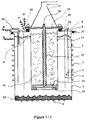
- FIG. 1/1 represents an example of arrangement of an electrolysis cell suitable for the method according to the invention using a bath containing HF.
- the tank for example in monel or steel internally covered with an inert coating resistant to bath and temperature, on the walls and the bottom of which are fixed respectively the coils (2) and (3) (or any other equivalent heating or cooling device) which allow the regulation of the temperature of the bath or its reheating, for example after cooling which has caused the bath to freeze.
- the coil (3) also serves to obtain a frozen bath layer (23) to isolate the bottom.
- the cathode compartment (4) is separated from the rest of the cell (anode compartment) using the diaphragm (5) fixed here to the cover (9) and comprising oblique holes, making it possible to confine the hydrogen formed which is then evacuated using the manifold (6). It comprises cathode blades (7), for example in monel, fixed to the cover (9) and plunging into the electrolysis bath whose surface is shown in (8).
- the cover passes an HF supply pipe (20).
- the cover is isolated from the body of the tank by a Teflon crown (10).
- the openwork anode basket (11), which contains the anode charge (21), is fixed to the cover (9) by means of a teflon crown (12).
- It can be made of carbon composite, but it can also be made of monel internally covered with a plastic insulator, teflon, fluorinated plastic ...
- teflon crown (13) At the bottom of said basket there is a teflon crown (13) on which a carbon disc rests (14) constituting the lower active part of the anode current supply.
- This arrangement makes it possible to force the current to pass through the lower disc (14) so as to preferably consume the alloy located at the back of the basket and causing the gases to percolate through the load, the supply of this zone with the alloy to be consumed then being done automatically by gravity.
- the upper disc (15) rests on an insulating crown (18) in Teflon which isolates it from the anode basket (11).
- the dome covering the anode basket and used to collect the gaseous fluoride formed. It is fixed directly to the upper disc (15) to ensure good electrical contact, possibly cooled by the coil (22).
- connection (D) to bring the anode current is made directly on the dome (19)
- connection K for the cathode current supply is made directly on the cover (9) in contact with the cathode (7).
- the connection (P) connected to the anode basket is used, if necessary, to control and / or measure the voltage of said basket.
- the current supply (Q) is used to control the potential of the tank (1) to prevent corrosion.
- the fluorination of a U alloy containing 10% Mo was carried out.
- a device was used in accordance with that described in FIG. 1.
- the bath is a KF, 2HF mixture maintained at 100 ° C.
- the tank (1) is made of steel covered internally with a monel envelope.
- the cathode blades (7) are in monel and the diaphragm (5), insulating, in teflon (fabrics of brand GORE-TEX) perforated with oblique holes.
- the anode basket (11) is made of "Aerolor" composite (registered trademark of Le Carbone Lorraine), based on two-dimensional carbon fibers, perforated and contains pieces of alloy weighing approximately 50 g.
- the anode current supply comprises a lower disc (14) and a connecting rod (16) in graphite, while the upper perforated disc (15), of the chariot wheel type, is in carbonaceous "Aérolor" composite. Sheath insulation (17) around the rod (16) is Teflon. The dome (19) is in monel.
- the cell and the cathode plates were connected together to be at the same potential, and the terminal P of the anode basket was left free to carry out measurements.
- the bath was then melted by circulation in the coils of a water-glycol mixture at 120 ° C., then injected cold air into the coil (3) of the bottom of the tank to obtain a bottom covered with a layer of frozen bath.
- a voltage was applied between the cathode terminal (K) and the anode terminal (D) taking into account the selective dissolution voltage of the uranium, the overvoltages and the ohmic losses of the device, so as to obtain an intensity of about 50A and to have a voltage of 1 V between (P) and (K) (anode basket and cathode), which allows better control of the selective dissolution reaction.
- the current density is then approximately 0.25 A / cm2 on the cathodes and is estimated at approximately 0.01 A / cm2 on the pieces of alloy.
- This voltage is kept approximately constant, however compensating for the ohmic losses which appear; similarly, a regular supply of HF is carried out so that the HF content of the bath is constant.
- the collected gases were analyzed continuously by mass spectrometry; it has been found that they consist essentially of UF6 with HF and MoF5 entrainments not exceeding about 0.05%. When the intensity dropped significantly, it was not possible to increase the voltage, to maintain said intensity at an acceptable level, without suddenly increasing the proportion of MoF5 in the gases collected.
- the steel tank (1) used was internally covered with fluorinated polypropylene; it was heated and its temperature was regulated at 60 ° C using hot air; the bath consists of a NH4F-3HF mixture.
- the cathode blades (7) are steel ribbons, the anode basket (11) is also made of fluorinated polypropylene; it also acts as a diaphragm, to separate the anode and cathode compartments, thanks to oblique holes made in its wall.
- the current supply is such as that described in FIG. 1, the insulating sheath (17) also being made of fluorinated polypropylene.
- the dome (19) is made of nickel.
- the intensity has been limited to 20A; as previously, the gases collected were analyzed continuously.
- the metal residues contained in the anode basket were treated as in Example 1; they titrate 0.03% U.
- the invention makes it possible to recover practically all of the U of an alloy, in a form such that it is directly usable so as to be possibly and easily adjusted, for example by dilution gaseous online, at a desired isotopic content, and for making nuclear fuels, knowing that this recovered uranium can be, before its nuclear use, completely purified by an easy-to-conduct distillation.
- this process does not generate parasitic effluents, does not consume reagent and / or energy to react with elements other than the metal to be recovered or reagent to neutralize unwanted effluents.
Landscapes
- Chemical & Material Sciences (AREA)
- Organic Chemistry (AREA)
- Electrochemistry (AREA)
- Chemical Kinetics & Catalysis (AREA)
- Materials Engineering (AREA)
- Metallurgy (AREA)
- Engineering & Computer Science (AREA)
- Inorganic Chemistry (AREA)
- Life Sciences & Earth Sciences (AREA)
- General Life Sciences & Earth Sciences (AREA)
- Geology (AREA)
- Electrolytic Production Of Non-Metals, Compounds, Apparatuses Therefor (AREA)
- Electrolytic Production Of Metals (AREA)
- Inorganic Compounds Of Heavy Metals (AREA)
Claims (13)
- Verfahren zur selektiven Elektrofluorierung von Legierungen oder von metallischen Mischungen auf der Basis von Uran, dadurch gekennzeichnet, daß eine selektive anodische Reaktion an mindestens einem der Legierungsbestandteile mit Hilfe einer gesteuerten anodischen Spannung in einem flüssigen Fluorbad stattfindet.
- Verfahren nach Anspruch 1, dadurch gekennzeichnet, daß die selektive Fluorierung auf der Basis von Uran erfolgt.
- Verfahren nach einem der Ansprüche 1 oder 2, dadurch gekennzeichnet, daß die Legierung in fragmentierter Form verwendet wird.
- Verfahren nach einem der Ansprüche 1 bis 3, dadurch gekennzeichnet, daß das flüssige Fluorbad Fluorwasserstoffsäure enthält.
- Verfahren nach Anspruch 4, dadurch gekennzeichnet, daß es sich bei dem Bad um ein KF-2HF- oder NH₄F-3HF-Bad handelt.
- Verfahren nach einem der Ansprüche 1 bis 4, dadurch gekennzeichnet, daß es in einer Elektrolysezelle durchgeführt wird, die in einer Wanne (1) angebracht ist, die mit einer Vorrichtung (2) ausgestattet ist, die erwärmt und abgekühlt werden kann, um das Bad zu verflüssigen, zu verfestigen und/oder die Temperatur des Bades konstant zu halten, ferner ausgestattet mit einer Metallkathode (7), einem Anodenkorb (11), der die zu behandelnde Legierung (21) und eine Anodenstromzuführung enthält, einem Diaphragma (5), das den anodische Teil vom kathodischen Teil abtrennt, einer Kuppel (19) zur Rückgewinnung von flüchtigen Fluoriden, die im Verlaufe der selektiven Fluorierung entstehen, sowie gegebenenfalls einem Wasserstoffkollektor (6).
- Verfahren nach Anspruch 6, dadurch gekennzeichnet, daß die Wanne als Kathode dient.
- Verfahren nach einem der Ansprüche 6 oder 7, dadurch gekennzeichnet, daß der Anodenkorb als Diaphragma dient.
- Verfahren nach einem der Ansprüche 6 bis 8, dadurch gekennzeichnet, daß die Anodenstromzuführung den genannten Strom von unten zuleitet.
- Verfahren nach einem der Ansprüche 6 bis 9, dadurch gekennzeichnet, daß die Wanne einen Deckel (9) umfaßt, der den Anodenkorb (11), die Rückgewinnungskuppel (19) sowie gegebenenfalls die Kathode (7) und den Wasserstoffkollektor (6) abstützt.
- Verfahren nach einem der Ansprüche 6 bis 10, dadurch gekennzeichnet, daß die Wanne aus Mantelstahl, Monelstahl, Nickel oder (vorzugsweise verstärktem) Kunststoff besteht.
- Verfahren nach einem der Ansprüche 6 bis 11, dadurch gekennzeichnet, daß der Anodenkorb aus Monelstahl besteht, der an der Innenseite mit Kunststoff, Kohlenstoff, (vorzugsweise verstärkten) Kohlenstoffasern oder Polyfluorethylen- bzw. Perfluorkunststoff verkleidet ist.
- Verfahren nach einem der Ansprüche 1 bis 12, dadurch gekennzeichnet, daß die Spannung der Legierung, des Anodenkorbs und der Wanne unabhängig voneinander gesteuert werden, und daß der Anodenkorb im Verhältnis zur Legierung vorzugsweise kathodisch polarisiert wird und aus Metall besteht, das an der Innenseite mit Kunststoff beschichtetet ist.
Applications Claiming Priority (2)
| Application Number | Priority Date | Filing Date | Title |
|---|---|---|---|
| FR929208333A FR2692880B1 (fr) | 1992-06-29 | 1992-06-29 | Procédé d'électro-fluoration sélective d'alliages ou de mélanges métalliques à base d'uranium. |
| FR9208333 | 1992-06-29 |
Publications (2)
| Publication Number | Publication Date |
|---|---|
| EP0577533A1 EP0577533A1 (de) | 1994-01-05 |
| EP0577533B1 true EP0577533B1 (de) | 1996-05-08 |
Family
ID=9431600
Family Applications (1)
| Application Number | Title | Priority Date | Filing Date |
|---|---|---|---|
| EP93420280A Expired - Lifetime EP0577533B1 (de) | 1992-06-29 | 1993-06-28 | Verfahren zur selektiven Elektrofluorierung von Legierungen oder von metallischen Mischungen auf der Basis von Uran |
Country Status (9)
| Country | Link |
|---|---|
| US (1) | US5340447A (de) |
| EP (1) | EP0577533B1 (de) |
| JP (1) | JPH0688266A (de) |
| CN (1) | CN1083547A (de) |
| CA (1) | CA2099335A1 (de) |
| DE (1) | DE69302529T2 (de) |
| FR (1) | FR2692880B1 (de) |
| RU (1) | RU2119554C1 (de) |
| UA (1) | UA27734C2 (de) |
Families Citing this family (16)
| Publication number | Priority date | Publication date | Assignee | Title |
|---|---|---|---|---|
| CZ430498A3 (cs) * | 1996-06-28 | 1999-04-14 | Novartis Ag | Kapalný pesticidní prostředek |
| US7794580B2 (en) * | 2004-04-21 | 2010-09-14 | Materials & Electrochemical Research Corp. | Thermal and electrochemical process for metal production |
| US7410562B2 (en) * | 2003-08-20 | 2008-08-12 | Materials & Electrochemical Research Corp. | Thermal and electrochemical process for metal production |
| US8116423B2 (en) | 2007-12-26 | 2012-02-14 | Thorium Power, Inc. | Nuclear reactor (alternatives), fuel assembly of seed-blanket subassemblies for nuclear reactor (alternatives), and fuel element for fuel assembly |
| JP5585883B2 (ja) | 2007-12-26 | 2014-09-10 | トリウム・パワー、インク | 核燃料集合体、核燃料集合体を含む軽水炉、及び核燃料集合体の使用方法 |
| CA2946210C (en) | 2008-12-25 | 2019-02-12 | Thorium Power, Inc. | A light-water reactor fuel assembly and fuel element thereof |
| US8367026B2 (en) * | 2009-10-29 | 2013-02-05 | Omotowa Bamidele A | Method of producing sulfur tetrafluoride from uranium tetrafluoride |
| US10170207B2 (en) | 2013-05-10 | 2019-01-01 | Thorium Power, Inc. | Fuel assembly |
| WO2011143172A1 (en) | 2010-05-11 | 2011-11-17 | Thorium Power, Inc. | Fuel assembly with metal fuel alloy kernel and method of manufacturing thereof |
| US10192644B2 (en) | 2010-05-11 | 2019-01-29 | Lightbridge Corporation | Fuel assembly |
| CN101994133B (zh) * | 2010-11-24 | 2012-10-17 | 中国原子能科学研究院 | 用于氧化物乏燃料干法后处理的熔盐体系 |
| US9382632B2 (en) | 2013-06-21 | 2016-07-05 | Savannah River Nuclear Solutions, Llc | Electrochemical fluorination for processing of used nuclear fuel |
| CN104746105B (zh) * | 2015-04-14 | 2017-06-06 | 锡矿山闪星锑业有限责任公司 | 一种分离含锑合金的装置及方法 |
| CN108269638A (zh) * | 2017-12-20 | 2018-07-10 | 中核四0四有限公司 | 一种带有外部冷却的乏燃料后处理工艺系统电解槽 |
| KR20250010132A (ko) * | 2018-08-02 | 2025-01-20 | 테슬라, 인크. | 전기화학적 용해를 통한 금속 황산염 제조 시스템 |
| WO2025179085A1 (en) * | 2024-02-23 | 2025-08-28 | Board Of Supervisors Of Louisiana State University And Agricultural And Mechanical College | Electrolyzer dynamic seal |
Family Cites Families (14)
| Publication number | Priority date | Publication date | Assignee | Title |
|---|---|---|---|---|
| US4704261A (en) * | 1955-01-17 | 1987-11-03 | The United States Of America As Represented By The United States Department Of Energy | Method for fluorination of uranium oxide |
| FR72440E (fr) * | 1957-11-05 | 1960-04-13 | Commissariat Energie Atomique | Perfectionnements apportés aux procédés et appareils du genre de ceux pour l'obtention du fluorure d'uranium |
| NL267653A (de) * | 1960-08-03 | 1900-01-01 | ||
| US3330742A (en) * | 1966-10-11 | 1967-07-11 | Roger D Piper | Electrolytic reduction of uranium hexafluoride to uranium metal in fused salt |
| US3373000A (en) * | 1966-11-01 | 1968-03-12 | Olin Mathieson | Process for preparing tetrafluorides and hexafluorides |
| BE729289A (de) * | 1968-03-09 | 1969-08-18 | ||
| DE2129939C3 (de) * | 1970-06-23 | 1974-02-21 | Agip Nucleare S.P.A., Rom | Verfahren zur elektrochemischen Erzeugung von Uranhexafluorid |
| DE2040426A1 (de) * | 1970-08-14 | 1972-02-17 | Kali Chemie Ag | Verfahren zur Wiedergewinnung von Uran als Uranhexafluorid aus verbrauchten,Uran und Thorium enthaltenden Kernbrenn- und/oder Brutstoffen |
| DE2449590C3 (de) * | 1974-10-18 | 1980-06-12 | Kernforschungszentrum Karlsruhe Gmbh, 7500 Karlsruhe | Verfahren zur Reinigung von in niedrigen Oxidationszuständen befindlichen Aktiniden |
| FR2365187A1 (fr) * | 1976-09-20 | 1978-04-14 | Commissariat Energie Atomique | Procede de retraitement par voie seche de combustibles nucleaires irradies et dispositif de transformation de solides en gaz a haute temperature |
| GB8417364D0 (en) * | 1984-07-06 | 1984-08-30 | British Nuclear Fuels Plc | Production of uranium tetrafluoride |
| US4783322A (en) * | 1984-08-01 | 1988-11-08 | The United States Of America As Represented By The United States Department Of Energy | Method for fluorination of actinide fluorides and oxyfluorides thereof using O2 F2 |
| USH659H (en) * | 1989-04-06 | 1989-08-01 | The United States Of America As Represented By The United States Department Of Energy | Process for electrolytically preparing uranium metal |
| US4995948A (en) * | 1989-07-24 | 1991-02-26 | The United States Of America As Represented By The United States Department Of Energy | Apparatus and process for the electrolytic reduction of uranium and plutonium oxides |
-
1992
- 1992-06-29 FR FR929208333A patent/FR2692880B1/fr not_active Expired - Fee Related
-
1993
- 1993-06-18 UA UA93002726A patent/UA27734C2/uk unknown
- 1993-06-21 US US08/079,287 patent/US5340447A/en not_active Expired - Fee Related
- 1993-06-28 DE DE69302529T patent/DE69302529T2/de not_active Expired - Fee Related
- 1993-06-28 RU RU93045579A patent/RU2119554C1/ru active
- 1993-06-28 EP EP93420280A patent/EP0577533B1/de not_active Expired - Lifetime
- 1993-06-28 CA CA002099335A patent/CA2099335A1/fr not_active Abandoned
- 1993-06-29 JP JP5185528A patent/JPH0688266A/ja active Pending
- 1993-06-29 CN CN93107714A patent/CN1083547A/zh active Pending
Also Published As
| Publication number | Publication date |
|---|---|
| DE69302529D1 (de) | 1996-06-13 |
| FR2692880A1 (fr) | 1993-12-31 |
| CA2099335A1 (fr) | 1995-04-15 |
| UA27734C2 (uk) | 2000-10-16 |
| JPH0688266A (ja) | 1994-03-29 |
| DE69302529T2 (de) | 1996-12-12 |
| US5340447A (en) | 1994-08-23 |
| FR2692880B1 (fr) | 1994-09-02 |
| EP0577533A1 (de) | 1994-01-05 |
| RU2119554C1 (ru) | 1998-09-27 |
| CN1083547A (zh) | 1994-03-09 |
Similar Documents
| Publication | Publication Date | Title |
|---|---|---|
| EP0577533B1 (de) | Verfahren zur selektiven Elektrofluorierung von Legierungen oder von metallischen Mischungen auf der Basis von Uran | |
| US5380406A (en) | Electrochemical method of producing eutectic uranium alloy and apparatus | |
| CA1079222A (fr) | Type de cellule d'electrolyse pour la preparation industrielle du fluor | |
| US4235863A (en) | Method of and cell for generating hydrogen | |
| FR2810996A1 (fr) | Procede d'electrolyse | |
| CH658259A5 (fr) | Procede de purification de l'aluminium. | |
| EP0570308B1 (de) | Legierungen aus Metall mit hohen Schmelzpunkten geeignet für die Umwandlung in homogene und rein Blöcke, und Herstellungsverfahren dieser Legierungen | |
| CH643000A5 (fr) | Procede de production d'aluminium d'extreme purete. | |
| FR2694769A1 (fr) | Procédé de traitement de déchets de graphite. | |
| CH410441A (fr) | Procédé d'affinage du silicium et du germanium | |
| CA2020494C (fr) | Procede d'obtention d'uranium a partir d'oxyde et utilisant une voie chlorure | |
| FR2587364A1 (fr) | Procede de reduction a l'etat metallique de chlorure de zirconium, de hafnium ou de titane utilisant du zinc ou de l'etain comme element d'etancheite | |
| EP0412935A1 (de) | Verfahren zum Aufarbeiten von Knopfzellen in Mischung mit anderen metallischen Gegenständen und Rückgewinnung der metallenen Bestandteile | |
| CA2496683C (fr) | Procede de prechauffage d'une cuve pour la production d'aluminium par electrolyse | |
| FR2533590A1 (fr) | Procede de preparation electrolytique d'aluminium a partir de chlorure d'aluminium | |
| FR2559473A1 (fr) | Procede de production de silicium purifieÿa | |
| CH618890A5 (de) | ||
| US4802970A (en) | Process for preparing fluorine by electrolysis of calcium fluoride | |
| JP2740621B2 (ja) | 使用済みナトリウム硫黄電池の処理方法 | |
| JP2025115365A (ja) | アルミニウム電析方法 | |
| BE649028A (de) | ||
| BE489046A (de) | ||
| Mamantov et al. | Production of Fluorine by the Electrolysis of Calcium Fluoride‐Containing Tetrafluoroborate Melts | |
| CH133252A (fr) | Appareil pour l'extraction électrolytique de métaux légers. | |
| Ginatta et al. | Preparation of solar grade amorphous silicon for photovoltaic cells by means of an electrolytic process |
Legal Events
| Date | Code | Title | Description |
|---|---|---|---|
| PUAI | Public reference made under article 153(3) epc to a published international application that has entered the european phase |
Free format text: ORIGINAL CODE: 0009012 |
|
| AK | Designated contracting states |
Kind code of ref document: A1 Designated state(s): DE GB NL |
|
| 17P | Request for examination filed |
Effective date: 19940310 |
|
| RAP1 | Party data changed (applicant data changed or rights of an application transferred) |
Owner name: COGEMA COMPAGNIE GENERALE DES MATIERES NUCLEAIRES |
|
| 17Q | First examination report despatched |
Effective date: 19950915 |
|
| GRAH | Despatch of communication of intention to grant a patent |
Free format text: ORIGINAL CODE: EPIDOS IGRA |
|
| GRAA | (expected) grant |
Free format text: ORIGINAL CODE: 0009210 |
|
| AK | Designated contracting states |
Kind code of ref document: B1 Designated state(s): DE GB NL |
|
| REF | Corresponds to: |
Ref document number: 69302529 Country of ref document: DE Date of ref document: 19960613 |
|
| GBT | Gb: translation of ep patent filed (gb section 77(6)(a)/1977) |
Effective date: 19960708 |
|
| PLBE | No opposition filed within time limit |
Free format text: ORIGINAL CODE: 0009261 |
|
| STAA | Information on the status of an ep patent application or granted ep patent |
Free format text: STATUS: NO OPPOSITION FILED WITHIN TIME LIMIT |
|
| 26N | No opposition filed | ||
| PGFP | Annual fee paid to national office [announced via postgrant information from national office to epo] |
Ref country code: DE Payment date: 20010615 Year of fee payment: 9 |
|
| PGFP | Annual fee paid to national office [announced via postgrant information from national office to epo] |
Ref country code: GB Payment date: 20010627 Year of fee payment: 9 |
|
| PGFP | Annual fee paid to national office [announced via postgrant information from national office to epo] |
Ref country code: NL Payment date: 20010628 Year of fee payment: 9 |
|
| REG | Reference to a national code |
Ref country code: GB Ref legal event code: IF02 |
|
| PG25 | Lapsed in a contracting state [announced via postgrant information from national office to epo] |
Ref country code: GB Free format text: LAPSE BECAUSE OF NON-PAYMENT OF DUE FEES Effective date: 20020628 |
|
| PG25 | Lapsed in a contracting state [announced via postgrant information from national office to epo] |
Ref country code: NL Free format text: LAPSE BECAUSE OF NON-PAYMENT OF DUE FEES Effective date: 20030101 Ref country code: DE Free format text: LAPSE BECAUSE OF NON-PAYMENT OF DUE FEES Effective date: 20030101 |
|
| GBPC | Gb: european patent ceased through non-payment of renewal fee |
Effective date: 20020628 |
|
| NLV4 | Nl: lapsed or anulled due to non-payment of the annual fee |
Effective date: 20030101 |