EP0575747A1 - Appareil bloquant le passage de fumée dans une installation pour le passage de conduites à travers un mur - Google Patents
Appareil bloquant le passage de fumée dans une installation pour le passage de conduites à travers un mur Download PDFInfo
- Publication number
- EP0575747A1 EP0575747A1 EP93108074A EP93108074A EP0575747A1 EP 0575747 A1 EP0575747 A1 EP 0575747A1 EP 93108074 A EP93108074 A EP 93108074A EP 93108074 A EP93108074 A EP 93108074A EP 0575747 A1 EP0575747 A1 EP 0575747A1
- Authority
- EP
- European Patent Office
- Prior art keywords
- flaps
- flap
- opening
- locking device
- wall
- Prior art date
- Legal status (The legal status is an assumption and is not a legal conclusion. Google has not performed a legal analysis and makes no representation as to the accuracy of the status listed.)
- Withdrawn
Links
Images

Classifications
-
- F—MECHANICAL ENGINEERING; LIGHTING; HEATING; WEAPONS; BLASTING
- F16—ENGINEERING ELEMENTS AND UNITS; GENERAL MEASURES FOR PRODUCING AND MAINTAINING EFFECTIVE FUNCTIONING OF MACHINES OR INSTALLATIONS; THERMAL INSULATION IN GENERAL
- F16L—PIPES; JOINTS OR FITTINGS FOR PIPES; SUPPORTS FOR PIPES, CABLES OR PROTECTIVE TUBING; MEANS FOR THERMAL INSULATION IN GENERAL
- F16L5/00—Devices for use where pipes, cables or protective tubing pass through walls or partitions
- F16L5/02—Sealing
- F16L5/04—Sealing to form a firebreak device
-
- A—HUMAN NECESSITIES
- A62—LIFE-SAVING; FIRE-FIGHTING
- A62C—FIRE-FIGHTING
- A62C2/00—Fire prevention or containment
- A62C2/06—Physical fire-barriers
Definitions
- the invention relates to a blocking device against the passage of smoke in a device for carrying out lines, such as cables, pipes or the like, through an opening in a wall separating two fire compartments, the device for carrying out the lines being arranged sealed against the wall in the wall opening
- the bulkhead box has a through opening opening on both sides of the wall, which receives the lines, in which fire protection and / or extinguishing agents only become effective in the event of a fire, and which closes the through opening at its mouth on both sides of the wall with a movable locking member is provided as well as in the Fire sections arranged on both sides of the wall smoke detectors controlled holding devices that can hold the locking member in the closed position, and means are provided which supply the bulkhead with an incombustible gas medium and can generate a flow of this gas medium at each mouth of the through opening to the outside.
- Such a locking device is described in the German patent application P 41 31 153.1, which is not part of the prior art.
- the holding devices are controlled so that when there is smoke in one of the two fire compartments, the blocking member located on the side of the wall opens, so that a flow of the gas medium which is directed outward from the bulkhead box through the opened mouth of the through opening arises, which prevents the ingress of smoke, flames, convection heat and the like into the bulkhead box.
- the gas medium consists of air, but can also have flame-suffocating properties, such as, in particular, nitrogen or carbon dioxide.
- the disadvantage here is that the opening cross section of the gas flow at the mouth of the through opening is relatively large due to the opening of the blocking member and therefore the maintenance of the gas flow requires correspondingly large amounts of gas. It is forbidden to reduce the size of the opening of the feed-through opening itself, since there would then no longer be enough space to make changes or additions to the line assignment of the feed-through opening without problems.
- the invention has for its object to provide a blocking device of the type mentioned in such a way that the generation of the outward gas flow requires as little gas as possible, or with a given amount of gas the gas flow can be maintained as long as possible.
- the locking members are normally always in the closed position and reliably assume the closed position again and again when they should have been opened, for example in connection with the work relating to the laying of the line in the lead-through opening. If smoke then occurs in one of the fire compartments, the locking members are held in the closed position at both mouths, so that the resulting gas flow no longer has to meet the entire mouth cross-section of the through-opening, but only the clear cross-section between the lines and the one opposite them Edge of the pawls.
- This cross section is significantly smaller than the full mouth cross section of the through opening, so that the gas flow at both mouths can be generated and maintained with a correspondingly lower gas consumption.
- the locking members can Furthermore, they no longer open if the fire protection and / or extinguishing agents become effective in the passage opening as the fire progresses. Esp. the fire retardants remain limited to the inside of the bulkhead, so that, for. B. by intumescent material located in the bulkhead, which greatly increases its original volume under the action of heat, the bulkhead and the through opening are reliably filled and closed.
- the locking members themselves can contribute to fire protection if they are themselves resistant to heat and fire, preferably made of a material based on calcium silicate.
- the blocking members can even contain intumescent material, which in the event of fire exits from the blocking members held in the closed position into the lead-through opening.
- the locking members are designed as flaps which are mounted with a horizontal pivot axis above the respective mouth of the through opening. Then the flaps can swing in and out of the lead-through opening and thus easily open the lead-through opening when working on the lines, be it that existing lines should be pulled out or new lines drawn in.
- the flaps always return automatically to the closed position, in which they only need to be held in place in the event of a fire. Even the force of gravity causes the flaps to return to the closed position. However, it is advisable to let larger restoring forces take effect for a reliable return of the flaps.
- the device preferred for resetting the flaps into the closed position therefore has a control link and a return spring which is increasingly tensioned when the flap is pivoted out of the closed position via the control link, thus forming an energy store for the flap reset.
- this can be achieved in that the flap bearings, in addition to pivoting, also permit displacements of the flap parallel to themselves and transversely to the flap pivot axis, the flap being supported in the direction of displacement against the return spring.
- the return spring is tensioned by moving the flap when opening.
- the flap bearings are preferably formed by bearing journals fixed to the bulkhead box and bearing slots provided in the flaps, into which the bearing journals protrude, the return springs being arranged between the bearing journals and the ends of the bearing slots facing away from the lines and the flaps with their flap edge lying on the same side on the Control scenes are supported.
- the control link can be realized in a very simple and expedient manner in that the flaps each engage with their upper edge in a groove formed in the bulkhead box wall, which is rounded in cross section and the side surfaces of which form the control link on which the flap joins the flap edge appropriately rounded edges come to rest.
- the holding devices for holding the flaps in the closed position preferably consist of inflatable inflatable bodies which are inflated to hold the flaps and in the gap between the bulkhead box wall and brace the flap.
- the inflatable bodies are expediently fastened to the bulkhead box wall and recesses are provided on the edge of the flaps, into which the inflatable bodies engage in a form-fitting manner in the inflated state. Because they are attached to the bulkhead box wall instead of to the flaps, the inflatable bodies can be supplied more easily with the pressure medium causing them to inflate, for which purpose they are preferably connected to a pressure source feeding the pressure medium via valves which can be controlled by the smoke detectors.
- the pressure medium usually compressed air, can be supplied to the bulkhead from the outside via a compressed gas line.
- the pressure source directly in the bulkhead box in the form of compressed gas storage tanks and the smoke detectors on the outside of the bulkhead box.
- the electrical supply of the smoke detectors and the valves can then be provided by batteries or accumulators installed in the bulkhead box.
- the inflatable bodies are designed as inflatable hoses extending continuously along the gap between the flap and the bulkhead box wall.
- the inflation hoses then seal the entire gap between the flap and the bulkhead wall, which further contributes to reducing the gas consumption for the outward gas flow. If the flap protrudes with its upper edge in a manner already described in a groove in the bulkhead box wall which forms the control link, it is advisable to countersink the inflatable body, which is designed as an inflation hose, in the apex line of the groove receiving the upper flap edge into the groove base.
- the inflation of the inflatable bodies can also cause the flap to move against the lines, so that in the event of a fire, the otherwise free space between the lower flap edge and the in the through-opening lines can be closed further, which in turn is advantageous for reducing the gas consumption for the outward gas flow.
- This additional sealing of the flaps against the lines proves to be particularly effective if, according to a further proposal of the invention, the flaps on their edge facing the lines have fringes lying between the lines, which advantageously consist of copper wire and then not only provide additional sealing, but also have a high level of flame retardancy.
- the gas used to generate the outward gas flow is first passed into the bulkhead box itself, and then from there to emerge at the mouths of the through opening, the resulting gas flows and gas turbulence within the bulkhead box can affect the effect of the fire protection and / or extinguishing agents in the Affect the bulkhead box in the further course of the fire, for example hinder the complete and tight filling of the bulkhead box and the lead-through opening with intumescent material rising in the fire heat.
- this danger can be avoided in that, in order to generate the outward gas flow at each mouth of the lead-through opening, the respective blocking member with the Has gas medium-fed channel system that forms on the outside of the line facing the edge of the locking member on the outside of a longitudinally extending row of channel openings for the gas outlet, the emerging gas jets directed obliquely downwards and outwards against the lines and together outside in front of the closed blocking member form the outward gas flow.
- these and the channel system for the gas flow are connected to the same compressed gas storage container within the bulkhead box, the connection of the channel system being carried out by flexible compressed gas lines running inside the bulkhead box.
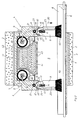
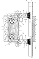
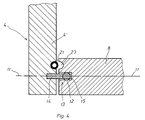
- the device shown in the drawing serves to fire-seal a wall opening for the passage of lines 1, such as cables or pipes, shown in the figures using only a single example, through a wall 2 and has a fire-resistant foam 3 sealed against the wall 2 in the wall opening arranged bulkhead box 4, which forms a through-opening 5 opening on both sides of the wall 2 and receiving the lines 1.
- the lines 1 lie on a line platform 6 passing through the lead-through opening 5.
- the bulkhead box 4 rests on the fire protection foam 3 on a reinforcing plate 7 made of incombustible material.
- the bulkhead box 4 has flaps 8 provided on both sides of the wall 2 for covering the mouths of the through opening 5, which flaps are pivotably mounted on the bulkhead box 4 in the edge region of the mouths of the through opening 5.
- the flaps 8 can be opened inwards or outwards for occupancy work, but always automatically return to the closed position covering the respective mouth, but are held in this closed position in the event of a fire.
- the holding devices serving the latter and to be described in more detail are controlled by fire and / or smoke detectors 9 arranged on both sides of the wall 2 on the bulkhead box 4.
- fire and / or smoke detectors 9 arranged on both sides of the wall 2 on the bulkhead box 4.
- the flaps 8 are mounted with a horizontal pivot axis 11 above the respective mouth of the through opening 5.
- return springs 12 which are increasingly tensioned when the flaps 8 are pivoted out of the closed position with the help of the control links 10 and thereby each form an energy store for the resetting of the flaps 8.
- the flap bearings 13 also allow displacements of the flaps 8 parallel to themselves and transversely to the flap pivot axis, the flaps 8 being supported in the direction of displacement against the return springs 12.
- the flap bearings 13 are formed by bearing journals 14 fixed on the bulkhead box 4 and bearing slots 15 provided in the flaps 8, into which the bearing journals 14 protrude.
- the return springs 12 are arranged between the bearing pins 14 and the ends 16 of the bearing slots 15 facing away from the lines.
- the flaps 8 can be supported on the control link 10 with their upper flap edge 17 lying on the same side.
- the flaps 8 engage with their upper edge 17 each in a groove 18 formed in the bulkhead wall, which is rounded in cross section and the side surfaces of which Form control links 10, on which the flap 8 comes to rest with correspondingly rounded edge surfaces 19 on the flap edge when pivoting.
- the elliptical groove or edge cross section ensures that the flaps 8 are pushed against the lines 1 when pivoting from the closed position in the direction of the arrow 20 and thereby tension the return springs 12, which then then flaps 8 over the control link 10 again push back into the closed position.
- the devices for holding the flaps 8 in the closed position consist of inflatable inflatable bodies 21 made of highly stretchable neoprene.
- the inflatable bodies 21 are inflated to hold the flaps with compressed air and then braced in the gap 22 between the bulkhead box wall 4 'and the flap.
- the inflatable bodies 21 are fastened to the bulkhead box wall 4 ', ie they do not take part in the flap movement themselves and can therefore be connected to the compressed air supply in a simple manner.
- recesses 23 are provided, in which the inflatable bodies 21 engage in a positive manner in the inflated state.
- the inflatable bodies 21 are designed as inflatable hoses which extend continuously along the gap 22 between the flap 8 and the partition wall 4 'and therefore, when inflated, seal the flap 8 against the partition wall 4' over the entire gap length, which is shown in FIG. 1 is indicated by dashed lines at 21 '.
- the inflatable body 21 is sunk into the groove base, so that it does not hinder the flap movement in the uninflated state.
- the respective flap 8 has a channel system 25 fed with the gas medium for the gas flow of channel openings 26 for the gas outlet.
- the gas jets emerging from the orifices 26 are directed obliquely downwards and outwards against the lines 1 and together form the outward gas flow outside the closed flap 8.
- the supply of this channel system 25 with the gas medium takes place through flexible compressed gas lines 27 running inside the bulkhead box, so that the gas medium cannot come into effect inside the bulkhead box 4 and within the lead-through opening 5 itself.
- the inflatable bodies 21 and the channel system 25 are connected to a compressed gas source 30 via valves 31, which are controlled by the fire and / or smoke detectors 9.
- the compressed gas source 30 consists of a plurality of compressed gas storage containers arranged in the bulkhead box 4, generally compressed air containers. If one of the detectors 9 responds, the valves open so that the inflatable bodies 21 inflate and at the same time the gas flow forms at the channel openings 26.
- the smoke detectors 9 and the valves 31 are supplied with electrical power by batteries or rechargeable batteries 32 indicated in the bulkhead box 4.
- fire protection means 40 in the form of an intumescent material are contained within the bulkhead case 4, which have the effect of heat of the fire multiplied its volume, thereby filling and closing the feed-through opening 5 and the bulkhead box 4.
- This fire protection agent 40 was located in a PE plastic bag 41 inside a container 42 arranged in the bulkhead box 4, the wall of which has openings 43 downwards to the passage opening 5, so that the fire protection agent 40 passes through these openings 43 into the passage opening 5 when in the fire heat of the pouch 41 enclosing the fire protection agent 40 begins to melt.
- the flaps 8 carry fringes 50 made of copper wire between the lines on their edge facing the lines 1.
Applications Claiming Priority (2)
| Application Number | Priority Date | Filing Date | Title |
|---|---|---|---|
| DE19924220449 DE4220449C1 (fr) | 1992-06-23 | 1992-06-23 | |
| DE4220449 | 1992-06-23 |
Publications (1)
| Publication Number | Publication Date |
|---|---|
| EP0575747A1 true EP0575747A1 (fr) | 1993-12-29 |
Family
ID=6461580
Family Applications (1)
| Application Number | Title | Priority Date | Filing Date |
|---|---|---|---|
| EP93108074A Withdrawn EP0575747A1 (fr) | 1992-06-23 | 1993-05-18 | Appareil bloquant le passage de fumée dans une installation pour le passage de conduites à travers un mur |
Country Status (2)
| Country | Link |
|---|---|
| EP (1) | EP0575747A1 (fr) |
| DE (1) | DE4220449C1 (fr) |
Cited By (2)
| Publication number | Priority date | Publication date | Assignee | Title |
|---|---|---|---|---|
| GB2318975A (en) * | 1996-05-01 | 1998-05-13 | Nullifire Ltd | Fire resistant duct |
| CN112003157A (zh) * | 2020-08-07 | 2020-11-27 | 李凯龙 | 一种基于水利工程电力输送用的配电柜自动灭火警示机构 |
Families Citing this family (1)
| Publication number | Priority date | Publication date | Assignee | Title |
|---|---|---|---|---|
| CN112354109A (zh) * | 2020-10-27 | 2021-02-12 | 湖南无双科技有限公司 | 一种基于智慧消防的室内安全预警装置及其预警方法 |
Citations (4)
| Publication number | Priority date | Publication date | Assignee | Title |
|---|---|---|---|---|
| CH636667A5 (en) * | 1978-12-28 | 1983-06-15 | Geberit Ag | Fire-extinguishing passage through walls or floors for flammable pipelines and cables |
| DE3932868A1 (de) * | 1988-10-05 | 1990-04-12 | Janka Zrl Radotin Statni Podni | Sicherheitsabsperrklappe gegen feueruebertragung durch lufttechnische rohrleitungen |
| DE9014517U1 (fr) * | 1990-10-19 | 1991-01-03 | Wichmann, Walter, 5952 Attendorn, De | |
| DE4131153C1 (fr) * | 1991-09-19 | 1992-11-12 | Werner 7925 Dischingen De Hauff |
-
1992
- 1992-06-23 DE DE19924220449 patent/DE4220449C1/de not_active Expired - Fee Related
-
1993
- 1993-05-18 EP EP93108074A patent/EP0575747A1/fr not_active Withdrawn
Patent Citations (4)
| Publication number | Priority date | Publication date | Assignee | Title |
|---|---|---|---|---|
| CH636667A5 (en) * | 1978-12-28 | 1983-06-15 | Geberit Ag | Fire-extinguishing passage through walls or floors for flammable pipelines and cables |
| DE3932868A1 (de) * | 1988-10-05 | 1990-04-12 | Janka Zrl Radotin Statni Podni | Sicherheitsabsperrklappe gegen feueruebertragung durch lufttechnische rohrleitungen |
| DE9014517U1 (fr) * | 1990-10-19 | 1991-01-03 | Wichmann, Walter, 5952 Attendorn, De | |
| DE4131153C1 (fr) * | 1991-09-19 | 1992-11-12 | Werner 7925 Dischingen De Hauff |
Cited By (4)
| Publication number | Priority date | Publication date | Assignee | Title |
|---|---|---|---|---|
| GB2318975A (en) * | 1996-05-01 | 1998-05-13 | Nullifire Ltd | Fire resistant duct |
| GB2318975B (en) * | 1996-05-01 | 2000-03-08 | Nullifire Ltd | Fire resistant duct |
| CN112003157A (zh) * | 2020-08-07 | 2020-11-27 | 李凯龙 | 一种基于水利工程电力输送用的配电柜自动灭火警示机构 |
| CN112003157B (zh) * | 2020-08-07 | 2022-04-29 | 广东海彬线槽有限公司 | 一种基于水利工程电力输送用的配电柜自动灭火警示机构 |
Also Published As
| Publication number | Publication date |
|---|---|
| DE4220449C1 (fr) | 1993-07-15 |
Similar Documents
| Publication | Publication Date | Title |
|---|---|---|
| DE3590606C2 (de) | Dichtungsvorrichtung für eine selbstschließende Schiebetür | |
| DE102004026649A1 (de) | Sauerstoffnotversorgungseinrichtung | |
| EP2555833A1 (fr) | Dispositif coupe-feu ou coupe-fumée | |
| DE69728518T2 (de) | Feuerbekämpfungseinrichtung | |
| EP0575747A1 (fr) | Appareil bloquant le passage de fumée dans une installation pour le passage de conduites à travers un mur | |
| DE4220448C1 (en) | Fire protection for wall entrance carrying cables - has fire-extinguishing medium in cabinet sealed within wall and cable access flaps closing if fire occurs | |
| DE4131153C1 (fr) | ||
| EP0824940A2 (fr) | Clapet coupe-feu | |
| DE4221862C1 (en) | Pipe and cable firestop for wall opening - has tension springs either side of inflatable securing flaps to box walls | |
| CH700709B1 (de) | Abdichtungssystem für tunnelartigen Durchgang, sowie Brandbekämpfungssystem. | |
| DE2848069A1 (de) | Feuerschutztuer, insbesondere fuer einen durchtritt eines foerderbandes durch eine wandoeffnung | |
| DE4131147C1 (fr) | ||
| DE4337565C1 (de) | Vorrichtung zur Durchführung von Leitungen durch eine Wandöffnung | |
| DE4316967C1 (de) | Vorrichtung zur Durchführung von Leitungen durch eine Wandöffnung | |
| DE4134915C1 (fr) | ||
| DE518305C (de) | Gesteinsstaubsperre mit Ausloesemittel fuer das Ventil einer Druckgasflasche | |
| DE10121550B4 (de) | Inertisierungsverfahren mit Stickstoffpuffer | |
| DE4131146C1 (fr) | ||
| DE4100750C2 (de) | Anlage zum Transport und zur Behandlung von einander gleichen Körpern | |
| EP0532886B1 (fr) | Dispositif coupe-feu placé dans l'ouverture d'une paroi pour la traversée de conduits | |
| EP0532888A2 (fr) | Dispositif coupe-feu placé dans l'ouverture d'une paroi pour la traversée de conduits | |
| DE10010270A1 (de) | Brandschutz-Sperrvorrichtung | |
| DE3044877A1 (de) | Feuerschutzabschluss fuer foerderkettendurchfuehrungen in brandschutzmauern | |
| DE102022112810A1 (de) | Vorrichtung und Verfahren zum Laden einer elektrischen Batterie | |
| DE3140043A1 (de) | Brandschutzklappe |
Legal Events
| Date | Code | Title | Description |
|---|---|---|---|
| PUAI | Public reference made under article 153(3) epc to a published international application that has entered the european phase |
Free format text: ORIGINAL CODE: 0009012 |
|
| AK | Designated contracting states |
Kind code of ref document: A1 Designated state(s): AT BE CH DK ES FR GB IT LI NL SE |
|
| STAA | Information on the status of an ep patent application or granted ep patent |
Free format text: STATUS: THE APPLICATION IS DEEMED TO BE WITHDRAWN |
|
| 18D | Application deemed to be withdrawn |
Effective date: 19940630 |