EP0575747A1 - Smoke passage cut-off device in a conduit lead-through installation - Google Patents
Smoke passage cut-off device in a conduit lead-through installation Download PDFInfo
- Publication number
- EP0575747A1 EP0575747A1 EP93108074A EP93108074A EP0575747A1 EP 0575747 A1 EP0575747 A1 EP 0575747A1 EP 93108074 A EP93108074 A EP 93108074A EP 93108074 A EP93108074 A EP 93108074A EP 0575747 A1 EP0575747 A1 EP 0575747A1
- Authority
- EP
- European Patent Office
- Prior art keywords
- flaps
- flap
- opening
- locking device
- wall
- Prior art date
- Legal status (The legal status is an assumption and is not a legal conclusion. Google has not performed a legal analysis and makes no representation as to the accuracy of the status listed.)
- Withdrawn
Links
Images

Classifications
-
- F—MECHANICAL ENGINEERING; LIGHTING; HEATING; WEAPONS; BLASTING
- F16—ENGINEERING ELEMENTS AND UNITS; GENERAL MEASURES FOR PRODUCING AND MAINTAINING EFFECTIVE FUNCTIONING OF MACHINES OR INSTALLATIONS; THERMAL INSULATION IN GENERAL
- F16L—PIPES; JOINTS OR FITTINGS FOR PIPES; SUPPORTS FOR PIPES, CABLES OR PROTECTIVE TUBING; MEANS FOR THERMAL INSULATION IN GENERAL
- F16L5/00—Devices for use where pipes, cables or protective tubing pass through walls or partitions
- F16L5/02—Sealing
- F16L5/04—Sealing to form a firebreak device
-
- A—HUMAN NECESSITIES
- A62—LIFE-SAVING; FIRE-FIGHTING
- A62C—FIRE-FIGHTING
- A62C2/00—Fire prevention or containment
- A62C2/06—Physical fire-barriers
Definitions
- the invention relates to a blocking device against the passage of smoke in a device for carrying out lines, such as cables, pipes or the like, through an opening in a wall separating two fire compartments, the device for carrying out the lines being arranged sealed against the wall in the wall opening
- the bulkhead box has a through opening opening on both sides of the wall, which receives the lines, in which fire protection and / or extinguishing agents only become effective in the event of a fire, and which closes the through opening at its mouth on both sides of the wall with a movable locking member is provided as well as in the Fire sections arranged on both sides of the wall smoke detectors controlled holding devices that can hold the locking member in the closed position, and means are provided which supply the bulkhead with an incombustible gas medium and can generate a flow of this gas medium at each mouth of the through opening to the outside.
- Such a locking device is described in the German patent application P 41 31 153.1, which is not part of the prior art.
- the holding devices are controlled so that when there is smoke in one of the two fire compartments, the blocking member located on the side of the wall opens, so that a flow of the gas medium which is directed outward from the bulkhead box through the opened mouth of the through opening arises, which prevents the ingress of smoke, flames, convection heat and the like into the bulkhead box.
- the gas medium consists of air, but can also have flame-suffocating properties, such as, in particular, nitrogen or carbon dioxide.
- the disadvantage here is that the opening cross section of the gas flow at the mouth of the through opening is relatively large due to the opening of the blocking member and therefore the maintenance of the gas flow requires correspondingly large amounts of gas. It is forbidden to reduce the size of the opening of the feed-through opening itself, since there would then no longer be enough space to make changes or additions to the line assignment of the feed-through opening without problems.
- the invention has for its object to provide a blocking device of the type mentioned in such a way that the generation of the outward gas flow requires as little gas as possible, or with a given amount of gas the gas flow can be maintained as long as possible.
- the locking members are normally always in the closed position and reliably assume the closed position again and again when they should have been opened, for example in connection with the work relating to the laying of the line in the lead-through opening. If smoke then occurs in one of the fire compartments, the locking members are held in the closed position at both mouths, so that the resulting gas flow no longer has to meet the entire mouth cross-section of the through-opening, but only the clear cross-section between the lines and the one opposite them Edge of the pawls.
- This cross section is significantly smaller than the full mouth cross section of the through opening, so that the gas flow at both mouths can be generated and maintained with a correspondingly lower gas consumption.
- the locking members can Furthermore, they no longer open if the fire protection and / or extinguishing agents become effective in the passage opening as the fire progresses. Esp. the fire retardants remain limited to the inside of the bulkhead, so that, for. B. by intumescent material located in the bulkhead, which greatly increases its original volume under the action of heat, the bulkhead and the through opening are reliably filled and closed.
- the locking members themselves can contribute to fire protection if they are themselves resistant to heat and fire, preferably made of a material based on calcium silicate.
- the blocking members can even contain intumescent material, which in the event of fire exits from the blocking members held in the closed position into the lead-through opening.
- the locking members are designed as flaps which are mounted with a horizontal pivot axis above the respective mouth of the through opening. Then the flaps can swing in and out of the lead-through opening and thus easily open the lead-through opening when working on the lines, be it that existing lines should be pulled out or new lines drawn in.
- the flaps always return automatically to the closed position, in which they only need to be held in place in the event of a fire. Even the force of gravity causes the flaps to return to the closed position. However, it is advisable to let larger restoring forces take effect for a reliable return of the flaps.
- the device preferred for resetting the flaps into the closed position therefore has a control link and a return spring which is increasingly tensioned when the flap is pivoted out of the closed position via the control link, thus forming an energy store for the flap reset.
- this can be achieved in that the flap bearings, in addition to pivoting, also permit displacements of the flap parallel to themselves and transversely to the flap pivot axis, the flap being supported in the direction of displacement against the return spring.
- the return spring is tensioned by moving the flap when opening.
- the flap bearings are preferably formed by bearing journals fixed to the bulkhead box and bearing slots provided in the flaps, into which the bearing journals protrude, the return springs being arranged between the bearing journals and the ends of the bearing slots facing away from the lines and the flaps with their flap edge lying on the same side on the Control scenes are supported.
- the control link can be realized in a very simple and expedient manner in that the flaps each engage with their upper edge in a groove formed in the bulkhead box wall, which is rounded in cross section and the side surfaces of which form the control link on which the flap joins the flap edge appropriately rounded edges come to rest.
- the holding devices for holding the flaps in the closed position preferably consist of inflatable inflatable bodies which are inflated to hold the flaps and in the gap between the bulkhead box wall and brace the flap.
- the inflatable bodies are expediently fastened to the bulkhead box wall and recesses are provided on the edge of the flaps, into which the inflatable bodies engage in a form-fitting manner in the inflated state. Because they are attached to the bulkhead box wall instead of to the flaps, the inflatable bodies can be supplied more easily with the pressure medium causing them to inflate, for which purpose they are preferably connected to a pressure source feeding the pressure medium via valves which can be controlled by the smoke detectors.
- the pressure medium usually compressed air, can be supplied to the bulkhead from the outside via a compressed gas line.
- the pressure source directly in the bulkhead box in the form of compressed gas storage tanks and the smoke detectors on the outside of the bulkhead box.
- the electrical supply of the smoke detectors and the valves can then be provided by batteries or accumulators installed in the bulkhead box.
- the inflatable bodies are designed as inflatable hoses extending continuously along the gap between the flap and the bulkhead box wall.
- the inflation hoses then seal the entire gap between the flap and the bulkhead wall, which further contributes to reducing the gas consumption for the outward gas flow. If the flap protrudes with its upper edge in a manner already described in a groove in the bulkhead box wall which forms the control link, it is advisable to countersink the inflatable body, which is designed as an inflation hose, in the apex line of the groove receiving the upper flap edge into the groove base.
- the inflation of the inflatable bodies can also cause the flap to move against the lines, so that in the event of a fire, the otherwise free space between the lower flap edge and the in the through-opening lines can be closed further, which in turn is advantageous for reducing the gas consumption for the outward gas flow.
- This additional sealing of the flaps against the lines proves to be particularly effective if, according to a further proposal of the invention, the flaps on their edge facing the lines have fringes lying between the lines, which advantageously consist of copper wire and then not only provide additional sealing, but also have a high level of flame retardancy.
- the gas used to generate the outward gas flow is first passed into the bulkhead box itself, and then from there to emerge at the mouths of the through opening, the resulting gas flows and gas turbulence within the bulkhead box can affect the effect of the fire protection and / or extinguishing agents in the Affect the bulkhead box in the further course of the fire, for example hinder the complete and tight filling of the bulkhead box and the lead-through opening with intumescent material rising in the fire heat.
- this danger can be avoided in that, in order to generate the outward gas flow at each mouth of the lead-through opening, the respective blocking member with the Has gas medium-fed channel system that forms on the outside of the line facing the edge of the locking member on the outside of a longitudinally extending row of channel openings for the gas outlet, the emerging gas jets directed obliquely downwards and outwards against the lines and together outside in front of the closed blocking member form the outward gas flow.
- these and the channel system for the gas flow are connected to the same compressed gas storage container within the bulkhead box, the connection of the channel system being carried out by flexible compressed gas lines running inside the bulkhead box.
- the device shown in the drawing serves to fire-seal a wall opening for the passage of lines 1, such as cables or pipes, shown in the figures using only a single example, through a wall 2 and has a fire-resistant foam 3 sealed against the wall 2 in the wall opening arranged bulkhead box 4, which forms a through-opening 5 opening on both sides of the wall 2 and receiving the lines 1.
- the lines 1 lie on a line platform 6 passing through the lead-through opening 5.
- the bulkhead box 4 rests on the fire protection foam 3 on a reinforcing plate 7 made of incombustible material.
- the bulkhead box 4 has flaps 8 provided on both sides of the wall 2 for covering the mouths of the through opening 5, which flaps are pivotably mounted on the bulkhead box 4 in the edge region of the mouths of the through opening 5.
- the flaps 8 can be opened inwards or outwards for occupancy work, but always automatically return to the closed position covering the respective mouth, but are held in this closed position in the event of a fire.
- the holding devices serving the latter and to be described in more detail are controlled by fire and / or smoke detectors 9 arranged on both sides of the wall 2 on the bulkhead box 4.
- fire and / or smoke detectors 9 arranged on both sides of the wall 2 on the bulkhead box 4.
- the flaps 8 are mounted with a horizontal pivot axis 11 above the respective mouth of the through opening 5.
- return springs 12 which are increasingly tensioned when the flaps 8 are pivoted out of the closed position with the help of the control links 10 and thereby each form an energy store for the resetting of the flaps 8.
- the flap bearings 13 also allow displacements of the flaps 8 parallel to themselves and transversely to the flap pivot axis, the flaps 8 being supported in the direction of displacement against the return springs 12.
- the flap bearings 13 are formed by bearing journals 14 fixed on the bulkhead box 4 and bearing slots 15 provided in the flaps 8, into which the bearing journals 14 protrude.
- the return springs 12 are arranged between the bearing pins 14 and the ends 16 of the bearing slots 15 facing away from the lines.
- the flaps 8 can be supported on the control link 10 with their upper flap edge 17 lying on the same side.
- the flaps 8 engage with their upper edge 17 each in a groove 18 formed in the bulkhead wall, which is rounded in cross section and the side surfaces of which Form control links 10, on which the flap 8 comes to rest with correspondingly rounded edge surfaces 19 on the flap edge when pivoting.
- the elliptical groove or edge cross section ensures that the flaps 8 are pushed against the lines 1 when pivoting from the closed position in the direction of the arrow 20 and thereby tension the return springs 12, which then then flaps 8 over the control link 10 again push back into the closed position.
- the devices for holding the flaps 8 in the closed position consist of inflatable inflatable bodies 21 made of highly stretchable neoprene.
- the inflatable bodies 21 are inflated to hold the flaps with compressed air and then braced in the gap 22 between the bulkhead box wall 4 'and the flap.
- the inflatable bodies 21 are fastened to the bulkhead box wall 4 ', ie they do not take part in the flap movement themselves and can therefore be connected to the compressed air supply in a simple manner.
- recesses 23 are provided, in which the inflatable bodies 21 engage in a positive manner in the inflated state.
- the inflatable bodies 21 are designed as inflatable hoses which extend continuously along the gap 22 between the flap 8 and the partition wall 4 'and therefore, when inflated, seal the flap 8 against the partition wall 4' over the entire gap length, which is shown in FIG. 1 is indicated by dashed lines at 21 '.
- the inflatable body 21 is sunk into the groove base, so that it does not hinder the flap movement in the uninflated state.
- the respective flap 8 has a channel system 25 fed with the gas medium for the gas flow of channel openings 26 for the gas outlet.
- the gas jets emerging from the orifices 26 are directed obliquely downwards and outwards against the lines 1 and together form the outward gas flow outside the closed flap 8.
- the supply of this channel system 25 with the gas medium takes place through flexible compressed gas lines 27 running inside the bulkhead box, so that the gas medium cannot come into effect inside the bulkhead box 4 and within the lead-through opening 5 itself.
- the inflatable bodies 21 and the channel system 25 are connected to a compressed gas source 30 via valves 31, which are controlled by the fire and / or smoke detectors 9.
- the compressed gas source 30 consists of a plurality of compressed gas storage containers arranged in the bulkhead box 4, generally compressed air containers. If one of the detectors 9 responds, the valves open so that the inflatable bodies 21 inflate and at the same time the gas flow forms at the channel openings 26.
- the smoke detectors 9 and the valves 31 are supplied with electrical power by batteries or rechargeable batteries 32 indicated in the bulkhead box 4.
- fire protection means 40 in the form of an intumescent material are contained within the bulkhead case 4, which have the effect of heat of the fire multiplied its volume, thereby filling and closing the feed-through opening 5 and the bulkhead box 4.
- This fire protection agent 40 was located in a PE plastic bag 41 inside a container 42 arranged in the bulkhead box 4, the wall of which has openings 43 downwards to the passage opening 5, so that the fire protection agent 40 passes through these openings 43 into the passage opening 5 when in the fire heat of the pouch 41 enclosing the fire protection agent 40 begins to melt.
- the flaps 8 carry fringes 50 made of copper wire between the lines on their edge facing the lines 1.
Abstract
Description
Die Erfindung betrifft eine Sperreinrichtung gegen Rauchdurchtritt bei einer Vorrichtung zur Durchführung von Leitungen, wie Kabel, Rohre oder dergl., durch eine Öffnung in einer zwei Brandabschnitte voneinander trennenden Wand, wobei die Vorrichtung zur Durchführung der Leitungen einen abgedichtet gegen die Wand in der Wandöffnung angeordneten Schottkasten aufweist, der eine auf beiden Seiten der Wand mündende, die Leitungen aufnehmende Durchführungsöffnung bildet, in der erst im Brandfall Brandschutz- und/oder Löschmittel wirksam werden, und der zum Abschließen der Durchführungsöffnung an deren Mündung auf beiden Seiten der Wand mit einem beweglichen Sperrglied versehen ist sowie von in den Brandabschnitten beidseits der Wand angeordneten Rauchmeldern gesteuerte Halteeinrichtungen aufweist, die das Sperrglied in der Schließstellung festhalten können, und wobei Mittel vorgesehen sind, die den Schottkasten mit einem unbrennbaren Gasmedium versorgen und eine Strömung dieses Gasmediums an jeder Mündung der Durchführungsöffnung nach außen erzeugen können.The invention relates to a blocking device against the passage of smoke in a device for carrying out lines, such as cables, pipes or the like, through an opening in a wall separating two fire compartments, the device for carrying out the lines being arranged sealed against the wall in the wall opening The bulkhead box has a through opening opening on both sides of the wall, which receives the lines, in which fire protection and / or extinguishing agents only become effective in the event of a fire, and which closes the through opening at its mouth on both sides of the wall with a movable locking member is provided as well as in the Fire sections arranged on both sides of the wall smoke detectors controlled holding devices that can hold the locking member in the closed position, and means are provided which supply the bulkhead with an incombustible gas medium and can generate a flow of this gas medium at each mouth of the through opening to the outside.
Eine derartige Sperreinrichtung ist in der zum nicht vorveröffentlichten Stand der Technik gehörenden deutschen Patentanmeldung P 41 31 153.1 beschrieben. Bei dieser Sperreinrichtung sind die Halteeinrichtungen so gesteuert, daß bei Rauch in einem der beiden Brandabschnitte sich das auf dessen Seite der Wand befindliche Sperrglied öffnet, so daß eine aus dem Schottkasten durch die geöffnete Mündung der Durchführungsöffnung hindurch nach außen gerichtete Strömung des Gasmediums entsteht, die das Eindringen von Rauch, Flammen, Konvektionswärme und dergl. in den Schottkasten hinein verhindert. Im einfachsten Fall besteht das Gasmedium aus Luft, kann aber auch flammenerstickende Eigenschaften besitzen, wie insbes. Stickstoff oder Kohlendyoxid. Nachteilig hierbei ist, daß durch die Öffnung des Sperrglieds der Austrittsquerschnitt der Gasströmung an der Mündung der Durchführungsöffnung verhältnismäßig groß ist und daher die Aufrechterhaltung der Gasströmung entsprechend große Gasmengen erfordert. Die Mündung der Durchführungsöffnung selbst zu verkleinern, verbietet sich, da dann kein ausreichender Platz mehr vorhanden wäre, Änderungen oder Ergänzungen in der Leitungsbelegung der Durchführungsöffnung problemlos auszuführen.Such a locking device is described in the German
Der Erfindung liegt die Aufgabe zugrunde, eine Sperreinrichtung der eingangs genannten Art so auszubilden, daß die Erzeugung der auswärts gerichteten Gasströmung möglichst wenig Gas erfordert, bzw. mit einer gegebenen Menge an Gas die Gasströmung möglichst lange aufrecht erhalten werden kann.The invention has for its object to provide a blocking device of the type mentioned in such a way that the generation of the outward gas flow requires as little gas as possible, or with a given amount of gas the gas flow can be maintained as long as possible.
Diese Aufgabe wird bei einer Sperreinrichtung mit den eingangs genannten Merkmalen nach der Erfindung dadurch gelöst, daß Einrichtungen zum Rückstellen der Sperrglieder in die Schließstellung vorgesehen sind und die Steuerung der Halteeinrichtung so ausgebildet ist, daß bei Rauch in einem der Brandabschnitte die Sperrglieder an beiden Mündungen der Durchführungsöffnung in der Schließstellung festgehalten werden.This object is achieved in a locking device with the features mentioned at the outset according to the invention in that devices for resetting the locking members into the closed position are provided and the control of the holding device is designed such that when there is smoke in one of the fire sections, the locking members at both mouths of the Feedthrough opening are held in the closed position.
Dadurch wird erreicht, daß die Sperrglieder normalerweise immer in der Schließstellung stehen und die Schließstellung auch zuverlässig immer wieder einnehmen, wenn sie, etwa im Zusammenhang mit die Leitungsverlegung in der Durchführungsöffnung betreffenden Arbeiten, geöffnet worden sein sollten. Tritt dann in einem der Brandabschnitte Rauch auf, werden die Sperrglieder an beiden Mündungen in der Schließstellung festgehalten, so daß die entstehende Gasströmung nicht mehr den gesamten Mündungsquerschnitt der Durchführungsöffnung zu erfüllen braucht, sondern nur noch den lichten Querschnitt zwischen den Leitungen und dem ihnen gegenüber liegenden Rand der Sperrglieder. Dieser Querschnitt ist wesentlich geringer als der volle Mündungsquerschnitt der Durchführungsöffnung, so daß die Gasströmung an beiden Mündungen mit entsprechend kleinerem Gasverbrauch erzeugt und aufrecht erhalten werden kann. Die Sperrglieder können sich im übrigen auch dann nicht mehr öffnen, wenn im weiteren Verlauf des Brandgeschehens die Brandschutz- und/oder Löschmittel in der Durchführungsöffnung wirksam werden. Insbes. bleiben dadurch die Brandschutzmittel auf das Innere des Schottkastens beschränkt, so daß z. B. durch im Schottkasten befindliches Intumeszenzmaterial, das unter Wärmeeinwirkung sein ursprüngliches Volumen stark vergrößert, der Schottkasten und die Durchführungsöffnung zuverlässig gefüllt und verschlossen werden. Die Sperrglieder selbst können dabei zum Brandschutz beitragen, wenn sie ihrerseits entsprechend gegen Wärme und Feuer widerstandsfähig sind, vorzugsweise aus einem Werkstoff auf der Basis von Calciumsilikat bestehen. Die Sperrglieder können sogar ihrerseits Intumeszenzmaterial enthalten, das im Brandfall aus den in der Schließstellung festgehaltenen Sperrgliedern in die Durchführungsöffnung austritt.It is thereby achieved that the locking members are normally always in the closed position and reliably assume the closed position again and again when they should have been opened, for example in connection with the work relating to the laying of the line in the lead-through opening. If smoke then occurs in one of the fire compartments, the locking members are held in the closed position at both mouths, so that the resulting gas flow no longer has to meet the entire mouth cross-section of the through-opening, but only the clear cross-section between the lines and the one opposite them Edge of the pawls. This cross section is significantly smaller than the full mouth cross section of the through opening, so that the gas flow at both mouths can be generated and maintained with a correspondingly lower gas consumption. The locking members can Furthermore, they no longer open if the fire protection and / or extinguishing agents become effective in the passage opening as the fire progresses. Esp. the fire retardants remain limited to the inside of the bulkhead, so that, for. B. by intumescent material located in the bulkhead, which greatly increases its original volume under the action of heat, the bulkhead and the through opening are reliably filled and closed. The locking members themselves can contribute to fire protection if they are themselves resistant to heat and fire, preferably made of a material based on calcium silicate. The blocking members can even contain intumescent material, which in the event of fire exits from the blocking members held in the closed position into the lead-through opening.
In bevorzugter Ausführungsform sind die Sperrglieder als Klappen ausgebildet, die mit horizontaler Schwenkachse oberhalb der jeweiligen Mündung der Durchführungsöffnung gelagert sind. Dann können die Klappen in der Durchführungsöffnung nach innen und außen pendeln und so bei Arbeiten an den Leitungen die Durchführungsöffnung ohne weiteres freigeben, sei es, daß vorhandene Leitungen heraus- oder neue Leitungen eingezogen werden sollen. Immer aber kehren die Klappen selbsttätig in die Schließstellung zurück, in der sie beim Eintreten eines Brandfalls nur noch festgehalten zu werden brauchen. Schon die-Schwerkraft bewirkt die Rückstellung der Klappen in die Schließstellung. Jedoch empfiehlt es sich, für eine zuverlässige Rückstellung der Klappen größere Rückstellkräfte wirksam werden zu lassen. Eine im Rahmen der Erfindung bevorzugte Einrichtung zum Rückstellen der Klappen in die Schließstellung besitzt daher je eine Steuerkulisse und eine Rückstellfeder, die beim Verschwenken der Klappe aus der Schließstellung heraus über die Steuerkulisse zunehmend gespannt wird, im Ergebnis also einen Kraftspeicher für die Klappenrückstellung bildet. In konstruktiv besonders einfacher und daher bevorzugter Weise kann dies dadurch verwirklicht werden, daß die Klappenlager außer Schwenkungen auch Verschiebungen der Klappe parallel zu sich selbst und quer zur Klappenschwenkachse ermöglichen, wobei die Klappe in Verschiebungsrichtung gegen die Rückstellfeder abgestützt ist. Durch die Verschiebung der Klappe beim Öffnen wird die Rückstellfeder gespannt. Vorzugsweise sind die Klappenlager von am Schottkasten festen Lagerzapfen und in den Klappen vorgesehenen Lagerschlitzen gebildet, in die die Lagerzapfen vorstehen, wobei die Rückstellfedern zwischen den Lagerzapfen und den den Leitungen abgewandten Enden der Lagerschlitze angeordnet und die Klappen mit ihrem auf derselben Seite liegenden Klappenrand an den Steuerkulissen abgestützt sind. Die Steuerkulisse kann dabei auf sehr einfache und zweckmäßige Weise dadurch verwirklicht werden, daß die Klappen mit ihrem oberen Rand je in eine in der Schottkastenwand ausgebildete Nut greifen, die im Querschnitt ausgerundet ist und deren Seitenflächen die Steuerkulisse bilden, an der die Klappe mit am Klappenrand entsprechend gerundeten Randflächen zur Anlage kommt.In a preferred embodiment, the locking members are designed as flaps which are mounted with a horizontal pivot axis above the respective mouth of the through opening. Then the flaps can swing in and out of the lead-through opening and thus easily open the lead-through opening when working on the lines, be it that existing lines should be pulled out or new lines drawn in. However, the flaps always return automatically to the closed position, in which they only need to be held in place in the event of a fire. Even the force of gravity causes the flaps to return to the closed position. However, it is advisable to let larger restoring forces take effect for a reliable return of the flaps. One in the frame The device preferred for resetting the flaps into the closed position therefore has a control link and a return spring which is increasingly tensioned when the flap is pivoted out of the closed position via the control link, thus forming an energy store for the flap reset. In a structurally particularly simple and therefore preferred manner, this can be achieved in that the flap bearings, in addition to pivoting, also permit displacements of the flap parallel to themselves and transversely to the flap pivot axis, the flap being supported in the direction of displacement against the return spring. The return spring is tensioned by moving the flap when opening. The flap bearings are preferably formed by bearing journals fixed to the bulkhead box and bearing slots provided in the flaps, into which the bearing journals protrude, the return springs being arranged between the bearing journals and the ends of the bearing slots facing away from the lines and the flaps with their flap edge lying on the same side on the Control scenes are supported. The control link can be realized in a very simple and expedient manner in that the flaps each engage with their upper edge in a groove formed in the bulkhead box wall, which is rounded in cross section and the side surfaces of which form the control link on which the flap joins the flap edge appropriately rounded edges come to rest.
Die Halteeinrichtungen zum Festhalten der Klappen in der Schließstellung bestehen vorzugweise aus aufblasbaren Blähkörpern, die zum Festhalten der Klappen aufgebläht werden und sich im Spalt zwischen der Schottkastenwand und der Klappe verspannen. Zweckmäßigerweise sind die Blähkörper an der Schottkastenwand befestigt und am Rand der Klappen Ausnehmungen vorgesehen, in welche die Blähkörper im aufgeblähten Zustand formschlüssig eingreifen. Durch ihre Befestigung an der Schottkastenwand statt an den Klappen können die Blähkörper einfacher mit dem ihr Aufblähen bewirkenden Druckmedium versorgt werden, wozu sie vorzugsweise mit einer das Druckmedium einspeisenden Druckquelle über Ventile verbunden sind, die durch die Rauchmelder steuerbar sind. Das Druckmedium, in der Regel Druckluft, kann dem Schottkasten von außen über eine Druckgasleitung zugeführt werden. Besser, einfacher und betriebssicherer aber ist es, die Druckquelle unmittelbar im Schottkasten in Form von Druckgas-Speicherbehältern und die Rauchmelder außen am Schottkasten anzuordnen. Die elektrische Versorgung der Rauchmelder und der Ventile kann dann durch im Schottkasten installierte Batterien oder Akkus erfolgen.The holding devices for holding the flaps in the closed position preferably consist of inflatable inflatable bodies which are inflated to hold the flaps and in the gap between the bulkhead box wall and brace the flap. The inflatable bodies are expediently fastened to the bulkhead box wall and recesses are provided on the edge of the flaps, into which the inflatable bodies engage in a form-fitting manner in the inflated state. Because they are attached to the bulkhead box wall instead of to the flaps, the inflatable bodies can be supplied more easily with the pressure medium causing them to inflate, for which purpose they are preferably connected to a pressure source feeding the pressure medium via valves which can be controlled by the smoke detectors. The pressure medium, usually compressed air, can be supplied to the bulkhead from the outside via a compressed gas line. It is better, simpler and more reliable to arrange the pressure source directly in the bulkhead box in the form of compressed gas storage tanks and the smoke detectors on the outside of the bulkhead box. The electrical supply of the smoke detectors and the valves can then be provided by batteries or accumulators installed in the bulkhead box.
Nach einem weiteren, besonders vorteilhaften Vorschlag der Erfindung sind die Blähkörper als sich durchgehend längs des Spaltes zwischen der Klappe und der Schottkastenwand erstreckende Blähschläuche ausgebildet. Im aufgeblähten Zustand ergeben dann die Blähschläuche eine Abdichtung des gesamten Spaltes zwischen der Klappe und der Schottkastenwandung, was weiter zur Verringerung des Gasverbrauchs für die auswärts gerichtete Gasströmung beiträgt. Ragt die Klappe mit ihrem oberen Rand in schon beschriebener Weise in eine mit den Seitenwänden die Steuerkulisse bildende Nut in der Schottkastenwand, so empfiehlt es sich, den als Blähschlauch ausgebildeten Blähkörper in der Scheitellinie der den oberen Klappenrand aufnehmenden Nut in den Nutgrund einzusenken. Soweit dabei die Klappe im übrigen in der ebenfalls schon beschriebenen Weise verschiebbar ist, kann das Aufblähen der Blähkörper, insbes. der Blähschläuche, auch ein Verschieben der Klappe gegen die Leitungen bewirken, wodurch im Brandfall auch der sonst noch vorhandene Freiraum zwichen dem unteren Klappenrand und den in der Durchführungsöffnung verlaufenden Leitungen weiter geschlossen werden kann, was wiederum zur Verringerung des Gasverbrauchs für die auswärts gerichtete Gasströmung vorteilhaft ist. Diese zusätzliche Abdichtung der Klappen gegen die Leitungen erweist sich dann als besonders wirksam, wenn gemäß einem weiteren Vorschlag der Erfindung die Klappen an ihrem den Leitungen zugekehrten Rand sich zwischen die Leitungen legende Fransen tragen, die zweckmäßigerweise aus Kupferdraht bestehen und dann nicht nur zusätzlich abdichtend, sondern auch in hohem Maße flammenhemmend wirken.According to a further, particularly advantageous proposal of the invention, the inflatable bodies are designed as inflatable hoses extending continuously along the gap between the flap and the bulkhead box wall. In the inflated state, the inflation hoses then seal the entire gap between the flap and the bulkhead wall, which further contributes to reducing the gas consumption for the outward gas flow. If the flap protrudes with its upper edge in a manner already described in a groove in the bulkhead box wall which forms the control link, it is advisable to countersink the inflatable body, which is designed as an inflation hose, in the apex line of the groove receiving the upper flap edge into the groove base. So far here the flap is otherwise displaceable in the manner already described, the inflation of the inflatable bodies, in particular the inflation hoses, can also cause the flap to move against the lines, so that in the event of a fire, the otherwise free space between the lower flap edge and the in the through-opening lines can be closed further, which in turn is advantageous for reducing the gas consumption for the outward gas flow. This additional sealing of the flaps against the lines proves to be particularly effective if, according to a further proposal of the invention, the flaps on their edge facing the lines have fringes lying between the lines, which advantageously consist of copper wire and then not only provide additional sealing, but also have a high level of flame retardancy.
Wird das zur Erzeugung der nach außen gerichteten Gasströmung dienende Gas zunächst in den Schottkasten selbst geleitet, um dann von da an den Mündungen der Durchführungsöffnung auszutreten, können die dadurch innerhalb des Schottkastens selbst entstehenden Gasströmungen und Gasturbulenzen die Wirkung der Brandschutz- und/oder Löschmittel im Schottkasten im weiteren Verlauf des Brandgeschehens störend beeinflussen, beispielsweise die vollständige und dichte Verfüllung des Schottkastens und der Durchführungsöffnung mit in der Brandhitze aufgehendem Intumeszenzmaterial behindern. In weiterer Ausbildung der Erfindung kann diese Gefahr dadurch vermieden werden, daß zur Erzeugung der auswärts gerichteten Gasströmung an jeder Mündung der Durchführungsöffnung das jeweilige Sperrglied ein mit dem Gasmedium gespeistes Kanalsystem aufweist, das an dem den Leitungen zugewandten Rand des Sperrglieds auf dessen Außenseite eine sich längs des Randes erstreckende Reihe von Kanalmündungen für den Gasaustritt bildet, wobei die austretenden Gasstrahlen schräg nach unten und außen gegen die Leitungen gerichtet sind und gemeinsam außen vor dem geschlossenen Sperrglied die auswärts gerichtete Gasströmung bilden. Vorzugsweise sind bei zum Festhalten der Sperrglieder in der Schließstellung vorgesehenen Blähkörpern diese und das Kanalsystem für die Gasströmung an denselben Druckgas-Speicherbehälter innerhalb des Schottkastens angeschlossen, wobei der Anschluß des Kanalsystems durch im Schottkasteninneren verlaufende flexible Druckgasleitungen erfolgt. Im Ergebnis wird erreicht, daß das die nach außen gerichtete Strömung erzeugende Gas in der Durchführungsöffnung selbst und im Schottkasten überhaupt nicht mehr wirksam werden, also dort auch die Wirkung der Brandschutz- und/oder Löschmittel nicht mehr beeinträchtigen kann.If the gas used to generate the outward gas flow is first passed into the bulkhead box itself, and then from there to emerge at the mouths of the through opening, the resulting gas flows and gas turbulence within the bulkhead box can affect the effect of the fire protection and / or extinguishing agents in the Affect the bulkhead box in the further course of the fire, for example hinder the complete and tight filling of the bulkhead box and the lead-through opening with intumescent material rising in the fire heat. In a further embodiment of the invention, this danger can be avoided in that, in order to generate the outward gas flow at each mouth of the lead-through opening, the respective blocking member with the Has gas medium-fed channel system that forms on the outside of the line facing the edge of the locking member on the outside of a longitudinally extending row of channel openings for the gas outlet, the emerging gas jets directed obliquely downwards and outwards against the lines and together outside in front of the closed blocking member form the outward gas flow. Preferably, in the case of inflatable bodies provided for holding the locking members in the closed position, these and the channel system for the gas flow are connected to the same compressed gas storage container within the bulkhead box, the connection of the channel system being carried out by flexible compressed gas lines running inside the bulkhead box. The result is that the gas generating the outward flow is no longer effective in the lead-through opening itself and in the bulkhead box, and therefore can no longer impair the action of the fire protection and / or extinguishing agent there.
Im folgenden wird die Erfindung an einem in der Zeichnung dargestellten Ausführungsbeispiel näher erläutert; es zeigen:
- Fig. 1
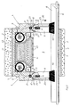
- eine Stirnansicht einer Vorrichtung zur Brandabschottung gemäß der Erfindung,
- Fig. 2
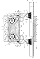
- den Schnitt II-II durch den Gegenstand der Fig. 1,
- Fig. 3
- den Schnitt III-III durch den Gegenstand der Fig. 1,
- Fig. 4
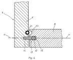
- den Schnitt IV-IV in Fig. 1.
- Fig. 1
- 1 shows an end view of a device for fire insulation according to the invention,
- Fig. 2
- the section II-II through the subject of Fig. 1,
- Fig. 3
- the section III-III through the subject of Fig. 1,
- Fig. 4
- the section IV-IV in Fig. 1st
Die in der Zeichnung dargestellte Vorrichtung dient zur Brandabschottung einer Wandöffnung für die Durchführung von in den Figuren lediglich an einem einzigen Beispiel dargestellten Leitungen 1, wie Kabel oder Rohre, durch eine Wand 2 und besitzt einen durch Brandschutzschaum 3 abgedichtet gegen die Wand 2 in der Wandöffnung angeordneten Schottkasten 4, der eine auf beide Seiten der Wand 2 mündende, die Leitungen 1 aufnehmende Durchführungsöffnung 5 bildet. Die Leitungen 1 liegen auf einer die Durchführungsöffnung 5 durchsetzenden Leitungspritsche 6. Der Schottkasten 4 ruht über den Brandschutzschaum 3 auf einer Verstärkungsplatte 7 aus unbrennbarem Material. In der Durchführungsöffnung 5 werden erst im Brandfall Brandschutz- und/oder Löschmittel wirksam, so daß die Durchführungsöffnung 5 normalerweise für Arbeiten zur Änderung oder Ergänzung der Leitungsbelegung offen und zugänglich ist. Der Schottkasten 4 besitzt auf beiden Seiten der Wand 2 zum Abdecken der Mündungen der Durchführungsöffnung 5 vorgesehene Klappen 8, die am Schottkasten 4 im Randbereich der Mündungen der Durchführungsöffnung 5 schwenkbar gelagert sind. Die Klappen 8 können für Belegungsarbeiten nach innen in den Schottkasten hinein oder nach außen geöffnet werden, stellen sich aber immer selbsttätig wieder in die die jeweilige Mündung abdeckende Schließstellung zurück, werden aber beim Eintreten eines Brandfalles in dieser Schließstellung festgehalten. Die zu letzterem dienenden, noch näher zu beschreibenden Halteeinrichtungen werden von beidseits der Wand 2 am Schottkasten 4 angeordneten Brand- und/oder Rauchmeldern 9 gesteuert. Außerdem besteht die Möglichkeit, an jeder Mündung der Durchführungsöffnung 5 eine nach außen gerichtete Strömung eines unbrennbaren Gasmediums zu erzeugen, die zu Beginn eines Brandfalles, wenn die Brandschutz- und/oder Löschmittel in der Durchführungsöffnung 4 noch nicht wirksam geworden ist, das Eindringen von Rauch in den Schottkasten 4 verhindert und somit eine Sperreinrichtung gegen Rauchdurchtritt bildet.The device shown in the drawing serves to fire-seal a wall opening for the passage of lines 1, such as cables or pipes, shown in the figures using only a single example, through a
Die Klappen 8 sind mit horizontaler Schwenkachse 11 oberhalb der jeweiligen Mündung der Durchführungsöffnung 5 gelagert. Zum Rückstellen der Klappen 8 in die Schließstellung dienen außer der Schwerkraft Steuerkulissen 10 und zwischen den Steuerkulissen 10 einerseits und der Schwenkachse 11 andererseits wirkende Rückstellfedern 12, die beim Verschwenken der Klappen 8 aus der Schließstellung heraus mit Hilfe der Steuerkulissen 10 zunehmend gespannt werden und dadurch jeweils einen Kraftspeicher für die Rückstellung der Klappen 8 bilden. Die Klappenlager 13 ermöglichen außer Schwenkungen auch Verschiebungen der Klappen 8 parallel zu sich selbst und quer zur Klappenschwenkachse, wobei die Klappen 8 in Verschiebungsrichtung gegen die Rückstellfedern 12 abgestützt sind. Die Klappenlager 13 sind von am Schottkasten 4 festen Lagerzapfen 14 und in den Klappen 8 vorgesehenen Lagerschlitzen 15 gebildet, in die die Lagerzapfen 14 vorstehen. Die Rückstellfedern 12 sind zwischen den Lagerzapfen 14 und den den Leitungen abgewandten Enden 16 der Lagerschlitze 15 angeordnet. Die Klappen 8 können sich mit ihrem auf derselben Seite liegenden, also oberen Klappenrand 17 an den Steuerkulissen 10 abgestützen. Dabei greifen die Klappen 8 mit ihrem oberen Rand 17 je in eine in der Schottkastenwand ausgebildete Nut 18, die im Querschnitt ausgerundet ist und deren Seitenflächen die Steuerkulissen 10 bilden, an der die Klappe 8 mit am Klappenrand entsprechend gerundeten Randflächen 19 beim Schwenken zur Anlage kommt. Durch den ellyptischen Nut- bzw. Randquerschnitt wird erreicht, daß die Klappen 8 beim Verschwenken aus der Schließstellung in Richtung des Pfeiles 20 gegen die Leitungen 1 vorgeschoben werden und sich dabei die Rückstellfedern 12 spannen, die dann anschließend die Klappen 8 über die Steuerkulissen 10 wieder in die Schließstellung zurückdrücken.The
Die Einrichtungen zum Festhalten der Klappen 8 in der Schließstellung bestehen aus aufblasbaren Blähkörpern 21 aus hoch dehnungsfähigem Neopren. Die Blähkörper 21 werden zum Festhalten der Klappen mit Druckluft aufgebläht und verspannen sich dann im Spalt 22 zwischen der Schottkastenwand 4' und der Klappe. Die Blähkörper 21 sind an der Schottkastenwand 4' befestigt, nehmen also an der Klappenbewegung selbst nicht teil und können daher in einfacher Weise an die Druckluftversorgung angeschlossen werden. Am Rand der Klappen 8 sind Ausnehmungen 23 vorgesehen, in welche die Blähkörper 21 im aufgeblähten Zustand formschlüssig eingreifen. Die Blähkörper 21 sind als Blähschläuche ausgebildet, die sich durchgehend längs der Spalte 22 zwischen der Klappe 8 und der Schottkastenwand 4' erstrecken und daher im aufgeblähten Zustand die Klappe 8 gegen die Schottkastenwand 4' über jeweils die gesamte Spaltlänge abdichten, was in Fig. 1 gestrichelt bei 21' angedeutet ist. In der Scheitellinie der den oberen Klappenrand 17 aufnehmenden Nut 18 ist der Blähkörper 21 in den Nutgrund eingesenkt, so daß er im nicht aufgeblähten Zustand die Klappenbewegung nicht behindert.The devices for holding the
Zur Erzeugung der auswärts gerichteten Gasströmung an jeder Mündung der Durchführungsöffnung 5 besitzt die jeweilige Klappe 8 ein mit dem Gasmedium für die Gasströmung gespeistes Kanalsystem 25. Dieses Kanalsystem 25 bildet im Bereich des den Leitungen 1 zugewandten Klappenrands auf der Klappenaußenseite eine sich längs des Klappenrands erstreckende Reihe von Kanalmündungen 26 für den Gasaustritt. Die aus den Mündungen 26 austretenden Gasstrahlen sind schräg nach unten und außen gegen die Leitungen 1 gerichtet und bilden gemeinsam außen vor der geschlossenen Klappe 8 die auswärts gerichtete Gasströmung. Die Versorgung dieses Kanalsystems 25 mit dem Gasmedium erfolgt durch im Schottkasteninneren verlaufende flexible Druckgasleitungen 27, so daß das Gasmedium im Inneren des Schottkastens 4 und innerhalb der Durchführungsöffnung 5 selbst nicht zur Wirkung kommen kann.In order to generate the outward gas flow at each mouth of the through opening 5, the
Die Blähkörper 21 und das Kanalsystem 25 sind mit einer Druckgasquelle 30 über Ventile 31 verbunden, die durch die Brand- und/oder Rauchmelder 9 gesteuert werden. Die Druckgasquelle 30 besteht aus mehreren im Schottkasten 4 angeordneten Druckgas-Speicherbehältern, in der Regel Druckluftbehältern. Spricht einer der Melder 9 an, öffnen sich die Ventile, so daß sich die Blähkörper 21 aufblähen und gleichzeitig die Gasströmung an den Kanalmündungen 26 bildet. Die elektrische Versorgung der Rauchmelder 9 und der Ventile 31 erfolgt durch im Schottkasten 4 angedeutete Batterien oder Akkus 32.The
Im Ausführungsbeispiel sind innerhalb des Schottkastens 4 lediglich Brandschutzmittel 40 in Form eines Intumeszenzmaterials enthalten, das in der Hitzewirkung des Brandes sein Volumen vervielfacht und dadurch die Durchführungsöffnung 5 und den Schottkasten 4 verfüllt und verschließt. Dieses Brandschutzmittel 40 befindete sich in einem PE-Kunststoffbeutel 41 innerhalb eines im Schottkasten 4 angeordneten Behälters 42, dessen Wand nach unten zur Durchführungsöffnung 5 hin Öffnungen 43 aufweist, so daß das Brandschutzmittel 40 durch diese Öffnungen 43 hindurch in die Durchführungsöffnung 5 gelangt, wenn in der Brandhitze der das Brandschutzmittel 40 einschließende Beutel 41 zu schmelzen beginnt.In the exemplary embodiment, only fire protection means 40 in the form of an intumescent material are contained within the
Die Klappen 8 tragen an ihrem den Leitungen 1 zugewandten Rand sich zwischen die Leitungen legende Fransen 50 aus Kupferdraht.The
Claims (17)
Applications Claiming Priority (2)
| Application Number | Priority Date | Filing Date | Title |
|---|---|---|---|
| DE4220449 | 1992-06-23 | ||
| DE19924220449 DE4220449C1 (en) | 1992-06-23 | 1992-06-23 |
Publications (1)
| Publication Number | Publication Date |
|---|---|
| EP0575747A1 true EP0575747A1 (en) | 1993-12-29 |
Family
ID=6461580
Family Applications (1)
| Application Number | Title | Priority Date | Filing Date |
|---|---|---|---|
| EP93108074A Withdrawn EP0575747A1 (en) | 1992-06-23 | 1993-05-18 | Smoke passage cut-off device in a conduit lead-through installation |
Country Status (2)
| Country | Link |
|---|---|
| EP (1) | EP0575747A1 (en) |
| DE (1) | DE4220449C1 (en) |
Cited By (2)
| Publication number | Priority date | Publication date | Assignee | Title |
|---|---|---|---|---|
| GB2318975A (en) * | 1996-05-01 | 1998-05-13 | Nullifire Ltd | Fire resistant duct |
| CN112003157A (en) * | 2020-08-07 | 2020-11-27 | 李凯龙 | Switch board automatic fire extinguishing warning mechanism based on hydraulic engineering electric power transmission uses |
Families Citing this family (1)
| Publication number | Priority date | Publication date | Assignee | Title |
|---|---|---|---|---|
| CN112354109A (en) * | 2020-10-27 | 2021-02-12 | 湖南无双科技有限公司 | Indoor safety early warning device based on intelligent fire fighting and early warning method thereof |
Citations (4)
| Publication number | Priority date | Publication date | Assignee | Title |
|---|---|---|---|---|
| CH636667A5 (en) * | 1978-12-28 | 1983-06-15 | Geberit Ag | Fire-extinguishing passage through walls or floors for flammable pipelines and cables |
| DE3932868A1 (en) * | 1988-10-05 | 1990-04-12 | Janka Zrl Radotin Statni Podni | AIr conduit safety shutter - comprises rectangular plate hinging at downstream end into recess flush with wall |
| DE9014517U1 (en) * | 1990-10-19 | 1991-01-03 | Wichmann, Walter, 5952 Attendorn, De | |
| DE4131153C1 (en) * | 1991-09-19 | 1992-11-12 | Werner 7925 Dischingen De Hauff |
-
1992
- 1992-06-23 DE DE19924220449 patent/DE4220449C1/de not_active Expired - Fee Related
-
1993
- 1993-05-18 EP EP93108074A patent/EP0575747A1/en not_active Withdrawn
Patent Citations (4)
| Publication number | Priority date | Publication date | Assignee | Title |
|---|---|---|---|---|
| CH636667A5 (en) * | 1978-12-28 | 1983-06-15 | Geberit Ag | Fire-extinguishing passage through walls or floors for flammable pipelines and cables |
| DE3932868A1 (en) * | 1988-10-05 | 1990-04-12 | Janka Zrl Radotin Statni Podni | AIr conduit safety shutter - comprises rectangular plate hinging at downstream end into recess flush with wall |
| DE9014517U1 (en) * | 1990-10-19 | 1991-01-03 | Wichmann, Walter, 5952 Attendorn, De | |
| DE4131153C1 (en) * | 1991-09-19 | 1992-11-12 | Werner 7925 Dischingen De Hauff |
Cited By (4)
| Publication number | Priority date | Publication date | Assignee | Title |
|---|---|---|---|---|
| GB2318975A (en) * | 1996-05-01 | 1998-05-13 | Nullifire Ltd | Fire resistant duct |
| GB2318975B (en) * | 1996-05-01 | 2000-03-08 | Nullifire Ltd | Fire resistant duct |
| CN112003157A (en) * | 2020-08-07 | 2020-11-27 | 李凯龙 | Switch board automatic fire extinguishing warning mechanism based on hydraulic engineering electric power transmission uses |
| CN112003157B (en) * | 2020-08-07 | 2022-04-29 | 广东海彬线槽有限公司 | Switch board automatic fire extinguishing warning mechanism based on hydraulic engineering electric power transmission uses |
Also Published As
| Publication number | Publication date |
|---|---|
| DE4220449C1 (en) | 1993-07-15 |
Similar Documents
| Publication | Publication Date | Title |
|---|---|---|
| DE3590606C2 (en) | Sealing device for a self-closing sliding door | |
| DE102004026649A1 (en) | Sauerstoffnotversorgungseinrichtung | |
| WO2011124374A1 (en) | Fire-protection or smoke-protection device | |
| DE69728518T2 (en) | FIRE FIGHTING EQUIPMENT | |
| EP0575747A1 (en) | Smoke passage cut-off device in a conduit lead-through installation | |
| DE4220448C1 (en) | Fire protection for wall entrance carrying cables - has fire-extinguishing medium in cabinet sealed within wall and cable access flaps closing if fire occurs | |
| DE4131153C1 (en) | ||
| DE8313824U1 (en) | FIRE CLOSURE FOR A CEILING BREAKTHROUGH OF A PATERNOSTER CONVEYING SYSTEM | |
| EP0824940A2 (en) | Fire damper | |
| DE4221862C1 (en) | Pipe and cable firestop for wall opening - has tension springs either side of inflatable securing flaps to box walls | |
| CH700709B1 (en) | Sealing system for tunnel-like passage, and fire fighting system. | |
| DE2848069A1 (en) | Conveyor belt passage fire damping door in wall - is in form of slider of flat box shape, with narrow underside bearing surface | |
| DE4131147C1 (en) | ||
| DE4316967C1 (en) | Cable or pipe entrance for opening in fire-resistant wall | |
| DE3140043C2 (en) | Fire damper | |
| DE4134915C1 (en) | ||
| DE518305C (en) | Rock dust barrier with release means for the valve of a pressurized gas cylinder | |
| DE4131146C1 (en) | ||
| DE4100750C2 (en) | Plant for the transport and treatment of identical bodies | |
| EP0532886B1 (en) | Fire barrier device through a wall opening for the penetration of conduits | |
| EP0532888A2 (en) | Fire barrier device through a wall opening for the penetration of conduits | |
| DE10010270A1 (en) | Fireproof blocking device has housing with closure element, detachable locking unit and intumescent material | |
| DE3044877A1 (en) | Fire-wall fireproof conveyor chain passage sealing case - has fireproof material filled top chamber with bottom seal opened under heat | |
| EP0655576B1 (en) | Device for the penetration of conduits through a wall opening | |
| DE102022112810A1 (en) | Device and method for charging an electric battery |
Legal Events
| Date | Code | Title | Description |
|---|---|---|---|
| PUAI | Public reference made under article 153(3) epc to a published international application that has entered the european phase |
Free format text: ORIGINAL CODE: 0009012 |
|
| AK | Designated contracting states |
Kind code of ref document: A1 Designated state(s): AT BE CH DK ES FR GB IT LI NL SE |
|
| STAA | Information on the status of an ep patent application or granted ep patent |
Free format text: STATUS: THE APPLICATION IS DEEMED TO BE WITHDRAWN |
|
| 18D | Application deemed to be withdrawn |
Effective date: 19940630 |