EP0575709B1 - Verfahren zur elektrolytischen Herstellung feinkörniger, einphasiger, metallischer Legierungspulver - Google Patents
Verfahren zur elektrolytischen Herstellung feinkörniger, einphasiger, metallischer Legierungspulver Download PDFInfo
- Publication number
- EP0575709B1 EP0575709B1 EP93105208A EP93105208A EP0575709B1 EP 0575709 B1 EP0575709 B1 EP 0575709B1 EP 93105208 A EP93105208 A EP 93105208A EP 93105208 A EP93105208 A EP 93105208A EP 0575709 B1 EP0575709 B1 EP 0575709B1
- Authority
- EP
- European Patent Office
- Prior art keywords
- process according
- cathode
- powder
- deposition
- powders
- Prior art date
- Legal status (The legal status is an assumption and is not a legal conclusion. Google has not performed a legal analysis and makes no representation as to the accuracy of the status listed.)
- Expired - Lifetime
Links
Images
Classifications
-
- C—CHEMISTRY; METALLURGY
- C25—ELECTROLYTIC OR ELECTROPHORETIC PROCESSES; APPARATUS THEREFOR
- C25C—PROCESSES FOR THE ELECTROLYTIC PRODUCTION, RECOVERY OR REFINING OF METALS; APPARATUS THEREFOR
- C25C5/00—Electrolytic production, recovery or refining of metal powders or porous metal masses
- C25C5/02—Electrolytic production, recovery or refining of metal powders or porous metal masses from solutions
-
- C—CHEMISTRY; METALLURGY
- C22—METALLURGY; FERROUS OR NON-FERROUS ALLOYS; TREATMENT OF ALLOYS OR NON-FERROUS METALS
- C22C—ALLOYS
- C22C1/00—Making non-ferrous alloys
- C22C1/04—Making non-ferrous alloys by powder metallurgy
Definitions
- the invention relates to a process for the electrolytic production of fine-grained, single-phase, metallic alloy powders, in particular powders of intermetallic compounds and noble metal alloy powders, in which one consists of a known, inorganic, electrolytic deposition bath which contains the alloy components to be deposited in solution, among known ones Powder deposition-producing electrolysis conditions galvanically generates powdery metallic deposits on the cathode.
- Metal powder has become very important with the rise of powder metallurgy.
- the manufacturing processes range from grinding brittle metals or alloys and atomizing melts to reducing powdery oxides and thermal decomposition or precipitation of organometallic compounds to chemical and electrolytic deposition.
- the different processes produce powders with very different properties.
- the morphological powder properties (particle shape, particle size distribution) play a major role in the processing steps of powder preparation, shaping and consolidation. This means that they also have a major influence on the residual porosity, the surface quality and the structure of the product.
- Electrolytically manufactured powders often consist of dendritic crystals. Powders produced on stationary electrodes show, depending on the electrolysis conditions, particle sizes between 300 and 1 ⁇ m.
- the powdery deposit on the cathode is generated in the electrolytic processes under conditions which are opposite to those of the electrolytic layer formation.
- the precipitates crystallize in powder form at high current densities, low metal ion concentrations and low bath temperatures.
- Vibrating or rotating electrodes are used to intensify the mass transport, which at the same time promote the throwing off of the powder grown on the electrode.
- the pulverulent precipitate thrown off or to be brushed off from the electrode collects either on the bottom of the electrolytic cell or in an organic medium submerged in the electrolyte (two-phase bath).
- a process for the electrolytic production of pourable powders from precious metals, in particular from platinum, palladium or gold, is known for example from DD-PS 139 605.
- powders of defined grain size should be able to be produced electrolytically if the deposition is carried out with solutions of the platinum metal hydrochloric acids and gold hydrochloric acids in the diffusion limit current range, ie in the range between solid deposition and hydrogen deposition.
- the grain size in the above-described process should be able to be influenced by varying the concentration, the temperature and the pH.
- a disadvantage of this known method is that the empirically determined ranges of values for the electrolysis parameters are very narrow and relate exclusively to the AgPd system and still to a specific deposition bath. It is not possible to transfer the results obtained to other deposition baths or other alloy systems.
- the object of the invention is to develop a method of the type mentioned at the outset in such a way that single-phase alloy powders can be produced electrolytically for almost any system.
- the driving force for alloy formation is the cathode potential alone.
- Single-phase alloy powders only develop above a critical cathode potential, which depends on the alloy composition. If the critical electrode potential is undershot, only segregated, i.e. heterogeneous alloy powder, with further reduction only mixtures of the individual metals.
- preliminary tests are carried out by successively increasing the cathode potential at otherwise constant, possibly also in preliminary tests with a view to making the method as simple and economical as possible, such as e.g. Bath composition and bath temperature, flow conditions in the border area in front of the cathode, type and nature of the cathode, from which cathode potential single-phase alloy powders are formed and then carries out the powder deposition at a cathode potential lying in the range of single-phase alloy formation.
- Bath composition and bath temperature flow conditions in the border area in front of the cathode, type and nature of the cathode, from which cathode potential single-phase alloy powders are formed
- the potentiostatic way of working is of particular importance. This means that not only can metal powders with a defined chemical and crystallographic composition be produced, but also with a very narrow grain size distribution and defined morphology.
- phase diagram is electrolytically created for an alloy system of interest, in which the phases found (with different symbols for different crystallographic structures) are plotted over the metal ion concentration ratio in the electrolyte depending on the cathode potential.
- metallic powders are deposited and examined for their chemical and crystallographic composition using suitable chemical and structure analysis methods, for example X-ray structure analysis.
- the number of measuring points for the phase diagram and their distribution over the concentration and potential range should be coordinated so that the areas of existence of the individual phases can be clearly delimited from one another with as few measuring points as possible.
- the phase diagram can extend over the entire composition range of the alloy system or only over a comparatively narrow, interesting concentration range.
- the procedure described above has the advantage that with repeated deposition of alloy powders from the same alloy system, but with different compositions, the cathode potential, from which a single-phase alloy formation occurs, must not be determined for each individual alloy composition in complex experiments.
- the critical cathode potential associated with any alloy composition can be read in a simple manner from the phase diagram once created for the alloy system.
- the process according to the invention can be carried out either continuously or batchwise.
- the latter means that the process must be interrupted at regular intervals and the metallic precipitate removed from the cathode mechanically, for example by brushing or stripping.
- the adhesion of the powder to the electrode depends on the physico-chemical properties of the deposited powder, on the electrolyte, on the electrolysis conditions - due to the influence of the crystallization of the powder (crystal shape, size) - on the surface properties of the electrode material (material, roughness, coating) with impurities and additives) and from external interventions such as oscillating, rotating or abrupt electrode movement, rising gas bubbles, use of ultrasound and mechanical brushing.
- the powder dropping behavior is influenced by a large number of interrelated factors in the interplay of the binding and detaching forces.
- laminar and / or turbulent flows of such a strength are generated in the area of the boundary layer in front of the cathode that the powder particles deposited on the cathode are continuously thrown off.
- this has the advantage that the relative movement between the electrolyte and the cathode increases the mass transfer and thus the productivity of the process.
- the relative movement between the electrolyte and the cathode is preferably generated in that the cathode is vibrated in a manner known per se during the deposition process, the powder-dropping behavior being variable within certain limits via the frequency and amplitude of the electrode vibrations.
- the vibration amplitude should be between 0.1 and 200 mm, the upper limit being essentially technical. Vibration amplitudes between 1 and 100 mm are more preferred.
- the relative movement between cathode and electrolyte can also advantageously be used to influence the grain size distribution of the deposited powder. If an oscillating electrode is used as the cathode, an increase in the oscillation width will generally lead to an increase in the grain size and possibly also to a broadening of the grain size distribution curve. However, this mode of operation can still be heavily dependent on the oscillation frequency. Very fine powders with a narrow distribution curve are usually obtained on a stationary cathode.
- the following properties of the alloy powders in particular can be set in a targeted manner: chemical and crystallographic composition, particle size distribution, particle shape and purity of the powder.
- cathode potential cathode potential
- bath composition in particular metal ion concentration ratio of the alloy components and total metal ion concentration
- flow conditions in the region of the boundary layer in front of the cathode - i.e. when using a vibrating electrode system: frequency and amplitude of the vibrating electrode - as well as bath temperature and material and surface quality of the cathode.
- the cathode potential also influences all other powder properties. In particular, it affects the grain size distribution of the powder, whereby there is a close connection with the powder dropping behavior.
- the cathodic decomposition e.g. hydrogen (with) deposition
- an increase in potential with otherwise constant process parameters causes a decrease in the grain size, while powder discharge goes through a maximum and finally to the full Can come to a standstill.
- the grain size of the powder generally continues to decrease, but the opposite stirring action can occur due to the cathodically generated gases.
- a strong gas development can also cause the powder to detach from the cathode again and the particle sizes to decrease.
- the upper limit of the cathode potential is essentially limited by economic aspects: with increasing cathode potential, the current yield decreases.
- the method according to the invention can be carried out with conventional galvanic deposition baths.
- Mandatory bath components are: a solvent, salts of the metals to be separated, at least one acid or alkali.
- the metals in the electrolyte are in the form of similar organic or inorganic compounds, for example in the form of inorganic salts, in particular in the form of very simple, non-complexing nitrates or chlorides. This has the advantage that the diffusion of the metal ions in the cathodic phase boundary layer and not the decomplexation of the metal ions determines the deposition rate. This results in higher deposition rates and easier powder formation.
- the chemical composition of the deposited powders is essentially determined via the metal ion concentration ratio of the alloy components in the electrolyte.
- the total metal ion concentration mainly affects the grain size, but also the productivity of the process. The following applies: the lower the metal ion concentration, the smaller the grain size, but the lower the current efficiency. The upper limit is given when the solubility product is reached. In addition, both the metal ion concentration ratio and the total metal ion concentration influence the powder dropping behavior.
- the pH value of the deposition bath is to be selected depending on the system, care being taken that a precipitation of the metal ions in the electrolyte triggered in a pH-dependent manner should also not occur in the area of the boundary layer in front of the cathode. Powder heavily contaminated by oxygen, for example, is otherwise to be expected.
- the pH should also be set so that the deposited powder largely does not corrode, ie the acid concentration should not be too high.
- One or more inorganic and / or organic additives are advantageously added to the deposition bath to influence the grain size and particle shape. These can, for example, improve the conductivity of the bath (possibly higher productivity, coarser powder), form complexes with one or all of the metal ions involved in the deposition, so that the respective free metal ion concentration drops or the deposition from the complex takes place with a changed deposition mechanism (change the grain size and morphology) or intervene in the electrocrystallization (also changing the grain size and morphology).
- Total concentrations of additives between 1 mg / l and 200 g / l are preferred. At concentrations below 1 mg / l, the measurable effectiveness of the additive diminishes too much. The upper limit is given by the maximum solubility of an additive.
- Preferred organic additives are proteins and / or protein degradation products, in particular gelatin, agar-agar, and / or surfactants, in particular sodium lauryl sulfate.
- Preferred inorganic additives are sulfates, chlorides and / or nitrates of the alkali metals, such as. B. Na2SO4, Li2SO4 and / or, insofar as soluble, also the alkaline earth metals, e.g. MgSO4.
- the bath temperature has almost no influence on the powder properties, but has considerable effects on the current yield and thus on the productivity of the process. This increases with increasing bath temperature.
- the upper limit of the bath temperature is limited to the physical and chemical area of existence of the solvent (e.g. water) and the components or to that of the finished electrolyte.
- the material of the cathode should be selected so that it is not corroded by the electrolyte and enables the powder to be easily separated. Suitable materials are e.g. Aluminum, titanium, stainless steel, nickel, gold or graphite.
- modifying the cathode surface for example by applying oxide layers or applying organic separating layers, such as. B. mineral oils, PTFE, the detachment of the powder from the cathode can be promoted. On the one hand, this results in finer powder (reduction in the mean residence time), and on the other hand the property spectrum of the powder can become narrower (homogenization of the residence time spectrum). A change in the powder morphology is only conceivable if the morphology changes with the dwell time on the electrode.
- the modification of the cathode surface itself takes place in process steps that take place before the actual electrolysis.
- the surface roughness of the cathode surface should be a maximum of a few mm, preferably only a few ⁇ m, in order to ensure that a high powder yield, a uniform powder separation behavior and thus also constant powder properties are achieved.
- the shape of the cathode should be such that the flow and potential distribution on the cathode surface is as uniform as possible. If a vibrating electrode is used as the cathode, this is preferred as a vertically arranged cylinder which is set to vibrate in the vertical direction.
- the method according to the invention can in principle be used for any alloy systems, for example also for alloys of the transition metals and tin alloys.
- alloys of the noble metals Pt, Ru, Rh, Pd, Os, Ir, Ag, Au are to be produced with the method according to the invention.
- the process according to the invention has the particular advantage that, for the first time, single-phase powders can be produced specifically for almost any alloy system. Not only are powders with sharply defined properties such as chemical and crystallographic composition, grain size and morphology obtained, the deposited powders are also characterized by a high level of purity due to the refining effect associated with electrolytic deposition, which is not possible using conventional methods is achievable.
- the powder was deposited using the three-electrode method known per se for electrochemical measurements.
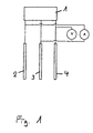
- the electrode arrangement used in this method is shown in FIG.
- the potentiostat is designated by (1) in FIG. 1, the counter electrode by (2), the working electrode by (3) and the reference electrode by (4).
- V and A denote a voltmeter and an ammeter, respectively.
- the centerpiece of the system consisted of a vibrating electrode that was connected to a potentiostat / galvanostat (model PAR 273, Princeton Applied Research) and a desktop computer (model 216, Hewlett Packard).
- the control of the separation process was partly computer-based.
- the vibrating electrode system used consisted of a sine generator (type TPO-25), the frequency and amplitude-variable signal of which controlled an electromagnetic vibrator (type 201, from Ling Dynamics), which in turn set the working electrode in vibration.
- the amplitude of the vibrating electrode was dependent on the frequency and reached a vibration range of 1.8 mm for coupled maximum values at a frequency of 50 Hz.
- a 600 ml wide-mouth glass vessel served as the electrolysis cell.
- the vibrating electrode was placed centrally in the electrolysis cell.
- An insoluble anode made of platinized titanium expanded metal was used as the counter electrode.
- the deposition potential and the concentrations of the alloy components were varied with constant total metal ion concentration in the case of powder deposition, with otherwise constant electrolysis conditions.
- the deposited powders were then examined for their chemical composition and crystallographic structure using methods known per se.
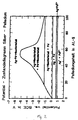
- FIG. 2 It can be seen in FIG. 2 that the alloying behavior of the AgPd system can be represented very clearly in a new type of phase diagram.
- the phases formed during powder deposition are plotted in FIG. 2 as a function of the cathode potential and, for the sake of simplicity, of the Pd concentration in the deposited powder.
- a representation with the metal ion concentration ratio as an abscissa could just as well be chosen.
- An advantage of this type of representation lies not only in the clarity, but in particular also in the simple possibility of reading the quantitative ratios of the separated phases by applying the lever law known per se.
- phase diagram presented here can only be viewed as a rough overview due to the relatively small number of measurement points on which it is based. Additional measurements would have to be carried out for the exact determination of the phase boundary lines.
- the diagram clearly shows the mixture gap within which the alloy powders crystallize heterogeneously. It turns out that two heterogeneous phase areas exist here. With low potentials, silver-rich mixed crystals are formed alongside palladium crystals. At higher potentials, in addition to the silver-rich, palladium-rich mixed crystals are formed until the gap in the mixture disappears with increasing electrode potential and single-phase AgPd alloy powders can be deposited over the entire concentration range.
- the critical potential for single-phase alloy formation depends on the AgPd concentration ratio in the electrolyte or on the alloy composition to be produced.
- the critical potential for a single-phase Ag50Pd50 alloy powder is still above -5 V (vs. SCE), while a single-phase Ag90Pd10 alloy powder is already deposited at -1 V.
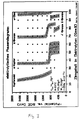
- the method according to the invention is also suitable for the production of single-phase powders of intermetallic compounds, as will be demonstrated below using the CuSn system.
- Intermetallic compounds are alloy phases with such a narrow concentration range that a certain stoichiometric composition of the alloy components can be specified.
Landscapes
- Chemical & Material Sciences (AREA)
- Engineering & Computer Science (AREA)
- Materials Engineering (AREA)
- Metallurgy (AREA)
- Organic Chemistry (AREA)
- Mechanical Engineering (AREA)
- Chemical Kinetics & Catalysis (AREA)
- Electrochemistry (AREA)
- Electrolytic Production Of Metals (AREA)
- Manufacture Of Metal Powder And Suspensions Thereof (AREA)
Applications Claiming Priority (2)
| Application Number | Priority Date | Filing Date | Title |
|---|---|---|---|
| DE4220849A DE4220849C1 (enExample) | 1992-06-25 | 1992-06-25 | |
| DE4220849 | 1992-06-25 |
Publications (2)
| Publication Number | Publication Date |
|---|---|
| EP0575709A1 EP0575709A1 (de) | 1993-12-29 |
| EP0575709B1 true EP0575709B1 (de) | 1996-05-08 |
Family
ID=6461808
Family Applications (1)
| Application Number | Title | Priority Date | Filing Date |
|---|---|---|---|
| EP93105208A Expired - Lifetime EP0575709B1 (de) | 1992-06-25 | 1993-03-30 | Verfahren zur elektrolytischen Herstellung feinkörniger, einphasiger, metallischer Legierungspulver |
Country Status (6)
| Country | Link |
|---|---|
| US (1) | US5370784A (enExample) |
| EP (1) | EP0575709B1 (enExample) |
| JP (1) | JP3265409B2 (enExample) |
| AT (1) | ATE137814T1 (enExample) |
| DE (2) | DE4220849C1 (enExample) |
| ES (1) | ES2086814T3 (enExample) |
Families Citing this family (17)
| Publication number | Priority date | Publication date | Assignee | Title |
|---|---|---|---|---|
| US5413987A (en) * | 1994-01-24 | 1995-05-09 | Midwest Research Institute | Preparation of superconductor precursor powders |
| DE4408512A1 (de) * | 1994-03-14 | 1995-09-21 | Studiengesellschaft Kohle Mbh | Verfahren zur Herstellung von hochdispersen Metallkolloiden und trägerfixierten Metallclustern |
| US5785837A (en) * | 1996-01-02 | 1998-07-28 | Midwest Research Institute | Preparation of transparent conductors ferroelectric memory materials and ferrites |
| CA2390647C (en) * | 1999-11-12 | 2008-03-25 | Michael A. Freeman | Method and composition for the triggered release of polymer-degrading agents for oil field use |
| US20040140222A1 (en) * | 2002-09-12 | 2004-07-22 | Smedley Stuart I. | Method for operating a metal particle electrolyzer |
| US7166203B2 (en) * | 2002-09-12 | 2007-01-23 | Teck Cominco Metals Ltd. | Controlled concentration electrolysis system |
| US7470351B2 (en) * | 2002-09-12 | 2008-12-30 | Teck Cominco Metals Ltd. | Discrete particle electrolyzer cathode and method of making same |
| US7273537B2 (en) * | 2002-09-12 | 2007-09-25 | Teck Cominco Metals, Ltd. | Method of production of metal particles through electrolysis |
| US6811625B2 (en) * | 2002-10-17 | 2004-11-02 | General Motors Corporation | Method for processing of continuously cast aluminum sheet |
| DE10259367A1 (de) * | 2002-12-18 | 2004-07-08 | Siemens Ag | Verfahren zur Verbesserung der Wechselwirkung zwischen einem Medium und einem Bauteil |
| JP4923763B2 (ja) | 2006-06-09 | 2012-04-25 | 富士ゼロックス株式会社 | 銀三角錐粒子の製造方法、及び銀三角錐粒子 |
| JP4527743B2 (ja) * | 2007-03-09 | 2010-08-18 | アサヒプリテック株式会社 | ルテニウム金属粉末の製造方法 |
| WO2011138876A1 (ja) * | 2010-05-07 | 2011-11-10 | Jx日鉱日石金属株式会社 | 印刷回路用銅箔 |
| JP5485239B2 (ja) * | 2010-09-17 | 2014-05-07 | 古河電気工業株式会社 | 銅微粒子の製造方法 |
| JP5654416B2 (ja) | 2011-06-07 | 2015-01-14 | Jx日鉱日石金属株式会社 | 液晶ポリマー銅張積層板及び当該積層板に用いる銅箔 |
| US9381588B2 (en) | 2013-03-08 | 2016-07-05 | Lotus BioEFx, LLC | Multi-metal particle generator and method |
| KR101637993B1 (ko) * | 2014-10-17 | 2016-07-11 | 한양대학교 에리카산학협력단 | 금속 분말 제조방법 및 제조장치 |
Family Cites Families (4)
| Publication number | Priority date | Publication date | Assignee | Title |
|---|---|---|---|---|
| GB1305562A (enExample) * | 1969-08-18 | 1973-02-07 | ||
| FR2526446B1 (fr) * | 1982-05-06 | 1986-02-21 | Penarroya Miniere Metall | Procede et appareil de preparation de metal par electrolyse, notamment de plomb, et demi-produit obtenu par leur mise en oeuvre |
| CA1226456A (en) * | 1984-01-12 | 1987-09-08 | Michael J. Pryor | Method and apparatus for producing acicular iron or iron alloy particles |
| FR2561265B1 (fr) * | 1984-03-16 | 1986-09-26 | Castillo Jean Michel | Procede de production de poudres fines et ultrafines de zinc par electrolyse en milieu basique |
-
1992
- 1992-06-25 DE DE4220849A patent/DE4220849C1/de not_active Expired - Fee Related
-
1993
- 1993-03-30 EP EP93105208A patent/EP0575709B1/de not_active Expired - Lifetime
- 1993-03-30 ES ES93105208T patent/ES2086814T3/es not_active Expired - Lifetime
- 1993-03-30 AT AT93105208T patent/ATE137814T1/de not_active IP Right Cessation
- 1993-03-30 DE DE59302492T patent/DE59302492D1/de not_active Expired - Fee Related
- 1993-06-17 JP JP16983493A patent/JP3265409B2/ja not_active Expired - Fee Related
- 1993-06-25 US US08/081,057 patent/US5370784A/en not_active Expired - Fee Related
Also Published As
| Publication number | Publication date |
|---|---|
| JPH06101085A (ja) | 1994-04-12 |
| ATE137814T1 (de) | 1996-05-15 |
| US5370784A (en) | 1994-12-06 |
| DE4220849C1 (enExample) | 1993-03-18 |
| JP3265409B2 (ja) | 2002-03-11 |
| ES2086814T3 (es) | 1996-07-01 |
| EP0575709A1 (de) | 1993-12-29 |
| DE59302492D1 (de) | 1996-06-13 |
Similar Documents
| Publication | Publication Date | Title |
|---|---|---|
| EP0575709B1 (de) | Verfahren zur elektrolytischen Herstellung feinkörniger, einphasiger, metallischer Legierungspulver | |
| DE2907179C2 (enExample) | ||
| DE2640225C2 (de) | Kathode für die Elektrolyse von Wasser oder Alkalichloridlösungen und Verfahren zu deren Herstellung | |
| DE2636550C3 (de) | Verfahren zum Herstellen von Ferro-Nickel-Granalien für die Galvanoplastik | |
| DE3640433C2 (enExample) | ||
| DE1105854B (de) | Bleidioxyd-Elektrode fuer elektrolytische Verfahren | |
| EP0279174A1 (de) | Verfahren zur Herstellung von Elektrolytmangandioxid | |
| DE202016007550U1 (de) | Galvanisch hergestellte Kupferlegierungen mit hoher Festigkeit und Leitfähigkeit | |
| DE3046913C2 (enExample) | ||
| DE2644199A1 (de) | Elektrolytische zelle zur anwendung in der hydroelektrometallurgie | |
| DE3029364A1 (de) | Verfahren zur herstellung von kathoden mit niedriger wasserstoffueberspannung und ihre verwendung | |
| DE2819964C2 (de) | Metallisches Diaphragma | |
| DE2931454A1 (de) | Verwendung von ferro-nickel-granalien | |
| DE2232903C3 (de) | Verfahren zur elektrolytischen Raffination von Kupfer unter Verwendung von Titanelektroden | |
| AT392293B (de) | Verfahren zum elektrolytischen galvanisieren | |
| DE3515742C2 (enExample) | ||
| DE2060066C3 (de) | Verfahren zur Herstellung von Magnesiumhydroxid und Chlorgas durch Elektrolyse von wäßrigen Elektrolyten, die in der Hauptmenge Magnesiumchlorid sowie Alkalichlorid gelöst enthalten | |
| DE2636552C3 (de) | Verwendung von Ferro-Nickel-Granalien | |
| DE19981314C2 (de) | Sputtertargetmaterial | |
| DE3208835A1 (de) | Unloesliche elektrode und elektrochemische vorrichtung | |
| WO2010046392A2 (de) | Elektrochemisches beschichtungsverfahren | |
| DE69213268T2 (de) | Verfahren zur Herstellung eines feinen dendritischen Pulvers und nach diesem Verfahren erzeugtes Pulver | |
| DE3132269C2 (enExample) | ||
| DE698478C (de) | genem Bleipulver | |
| WO2005021429A1 (de) | Verfahren zur herstellung einer schicht oder eines filmes aus einem metall-nanotube-verbundwerkstoff |
Legal Events
| Date | Code | Title | Description |
|---|---|---|---|
| PUAI | Public reference made under article 153(3) epc to a published international application that has entered the european phase |
Free format text: ORIGINAL CODE: 0009012 |
|
| AK | Designated contracting states |
Kind code of ref document: A1 Designated state(s): AT CH DE ES FR GB IT LI |
|
| 17P | Request for examination filed |
Effective date: 19931126 |
|
| 17Q | First examination report despatched |
Effective date: 19950406 |
|
| GRAH | Despatch of communication of intention to grant a patent |
Free format text: ORIGINAL CODE: EPIDOS IGRA |
|
| GRAA | (expected) grant |
Free format text: ORIGINAL CODE: 0009210 |
|
| AK | Designated contracting states |
Kind code of ref document: B1 Designated state(s): AT CH DE ES FR GB IT LI |
|
| REF | Corresponds to: |
Ref document number: 137814 Country of ref document: AT Date of ref document: 19960515 Kind code of ref document: T |
|
| ITF | It: translation for a ep patent filed | ||
| REF | Corresponds to: |
Ref document number: 59302492 Country of ref document: DE Date of ref document: 19960613 |
|
| ET | Fr: translation filed | ||
| REG | Reference to a national code |
Ref country code: ES Ref legal event code: FG2A Ref document number: 2086814 Country of ref document: ES Kind code of ref document: T3 |
|
| GBT | Gb: translation of ep patent filed (gb section 77(6)(a)/1977) |
Effective date: 19960730 |
|
| PLBE | No opposition filed within time limit |
Free format text: ORIGINAL CODE: 0009261 |
|
| 26N | No opposition filed | ||
| REG | Reference to a national code |
Ref country code: GB Ref legal event code: IF02 |
|
| PGFP | Annual fee paid to national office [announced via postgrant information from national office to epo] |
Ref country code: GB Payment date: 20020222 Year of fee payment: 10 |
|
| PGFP | Annual fee paid to national office [announced via postgrant information from national office to epo] |
Ref country code: CH Payment date: 20020225 Year of fee payment: 10 |
|
| PGFP | Annual fee paid to national office [announced via postgrant information from national office to epo] |
Ref country code: AT Payment date: 20020307 Year of fee payment: 10 |
|
| PGFP | Annual fee paid to national office [announced via postgrant information from national office to epo] |
Ref country code: FR Payment date: 20020315 Year of fee payment: 10 |
|
| PGFP | Annual fee paid to national office [announced via postgrant information from national office to epo] |
Ref country code: ES Payment date: 20020320 Year of fee payment: 10 |
|
| PG25 | Lapsed in a contracting state [announced via postgrant information from national office to epo] |
Ref country code: GB Free format text: LAPSE BECAUSE OF NON-PAYMENT OF DUE FEES Effective date: 20030330 Ref country code: AT Free format text: LAPSE BECAUSE OF NON-PAYMENT OF DUE FEES Effective date: 20030330 |
|
| PG25 | Lapsed in a contracting state [announced via postgrant information from national office to epo] |
Ref country code: LI Free format text: LAPSE BECAUSE OF NON-PAYMENT OF DUE FEES Effective date: 20030331 Ref country code: ES Free format text: LAPSE BECAUSE OF NON-PAYMENT OF DUE FEES Effective date: 20030331 Ref country code: CH Free format text: LAPSE BECAUSE OF NON-PAYMENT OF DUE FEES Effective date: 20030331 |
|
| REG | Reference to a national code |
Ref country code: CH Ref legal event code: PL |
|
| GBPC | Gb: european patent ceased through non-payment of renewal fee |
Effective date: 20030330 |
|
| PG25 | Lapsed in a contracting state [announced via postgrant information from national office to epo] |
Ref country code: FR Free format text: LAPSE BECAUSE OF NON-PAYMENT OF DUE FEES Effective date: 20031127 |
|
| REG | Reference to a national code |
Ref country code: FR Ref legal event code: ST |
|
| REG | Reference to a national code |
Ref country code: ES Ref legal event code: FD2A Effective date: 20030331 |
|
| PG25 | Lapsed in a contracting state [announced via postgrant information from national office to epo] |
Ref country code: IT Free format text: LAPSE BECAUSE OF NON-PAYMENT OF DUE FEES;WARNING: LAPSES OF ITALIAN PATENTS WITH EFFECTIVE DATE BEFORE 2007 MAY HAVE OCCURRED AT ANY TIME BEFORE 2007. THE CORRECT EFFECTIVE DATE MAY BE DIFFERENT FROM THE ONE RECORDED. Effective date: 20050330 |
|
| PGFP | Annual fee paid to national office [announced via postgrant information from national office to epo] |
Ref country code: DE Payment date: 20060524 Year of fee payment: 14 |
|
| PG25 | Lapsed in a contracting state [announced via postgrant information from national office to epo] |
Ref country code: DE Free format text: LAPSE BECAUSE OF NON-PAYMENT OF DUE FEES Effective date: 20071002 |