EP0575005A1 - Vorrichtung zum Reinigen und Sterilisieren von Kunststoffstopfen oder dergleichen zur Verwendung in pharmazeutischen Behältern - Google Patents
Vorrichtung zum Reinigen und Sterilisieren von Kunststoffstopfen oder dergleichen zur Verwendung in pharmazeutischen Behältern Download PDFInfo
- Publication number
- EP0575005A1 EP0575005A1 EP93201722A EP93201722A EP0575005A1 EP 0575005 A1 EP0575005 A1 EP 0575005A1 EP 93201722 A EP93201722 A EP 93201722A EP 93201722 A EP93201722 A EP 93201722A EP 0575005 A1 EP0575005 A1 EP 0575005A1
- Authority
- EP
- European Patent Office
- Prior art keywords
- washing
- plugs
- basket
- sterilizing apparatus
- fixed
- Prior art date
- Legal status (The legal status is an assumption and is not a legal conclusion. Google has not performed a legal analysis and makes no representation as to the accuracy of the status listed.)
- Withdrawn
Links
Images


Classifications
-
- B—PERFORMING OPERATIONS; TRANSPORTING
- B01—PHYSICAL OR CHEMICAL PROCESSES OR APPARATUS IN GENERAL
- B01J—CHEMICAL OR PHYSICAL PROCESSES, e.g. CATALYSIS OR COLLOID CHEMISTRY; THEIR RELEVANT APPARATUS
- B01J3/00—Processes of utilising sub-atmospheric or super-atmospheric pressure to effect chemical or physical change of matter; Apparatus therefor
- B01J3/04—Pressure vessels, e.g. autoclaves
-
- B—PERFORMING OPERATIONS; TRANSPORTING
- B08—CLEANING
- B08B—CLEANING IN GENERAL; PREVENTION OF FOULING IN GENERAL
- B08B3/00—Cleaning by methods involving the use or presence of liquid or steam
- B08B3/04—Cleaning involving contact with liquid
- B08B3/041—Cleaning travelling work
- B08B3/042—Cleaning travelling work the loose articles or bulk material travelling gradually through a drum or other container, e.g. by helix or gravity
-
- B—PERFORMING OPERATIONS; TRANSPORTING
- B01—PHYSICAL OR CHEMICAL PROCESSES OR APPARATUS IN GENERAL
- B01J—CHEMICAL OR PHYSICAL PROCESSES, e.g. CATALYSIS OR COLLOID CHEMISTRY; THEIR RELEVANT APPARATUS
- B01J2219/00—Chemical, physical or physico-chemical processes in general; Their relevant apparatus
- B01J2219/18—Details relating to the spatial orientation of the reactor
- B01J2219/182—Details relating to the spatial orientation of the reactor horizontal
Definitions
- the present invention relates to an apparatus for a) washing, b) rinsing, c) treating where necessary with additives, d) steam-sterilizing and e) drying the delicate components of a pharmaceutical container.
- These components include, among other things, plugs or stoppers and pistons made of elastomeric material, caps and covering devices; ring-nuts, capsules and other devices for fixing plugs and other members.
- the said methods of treatment assume greater importance when the drug is of the injectable type, and become of critical importance when the drug must be packaged under aseptic conditions, i.e. without final sterilization.
- hygroscopic powders for example antibiotics
- phial tubes are filled aseptically with a sterile fluid.
- plugs or small pistons must be sterile and be free of adherent particles.
- the plugs moreover, must be perfectly dry if they are used to close bottles containing hygroscopic or lyophilized powders.
- Treatment with additives may become of extreme importance when, for example, a very thin film of silicone (lubricant) must be spread on the members which are to be introduced into the necks of the bottles or flasks (plugs) or into prefilled syringes (pistons).
- silicone lubricant
- this machine only partially achieves the results sought after, in particular with regard to correct washing of the plugs, since, being a machine which is intended to wash a large number of plugs at a time, a large number of plugs accumulate on the bottom of the horizontal rotating cylindrical basket of the said machine, such that the dirty water dripping from the last-washed plugs comes into contact with the plugs accumulated on the bottom of the basket, with the risk that the plugs are not cleaned properly on account of the redeposition of dirt on the said plugs accumulated on the bottom of the basket.
- the basket rotates and jets of washing liquid are provided, oriented in a fixed manner with respect to said basket, it is necessary to ensure that nozzles generating said jets rotate together with the said basket, for example by providing a hollow shaft along the axis of the basket which acts as a supply duct for the nozzles and by connecting said hollow shaft to pipes for supplying washing liquid under pressure via a sealed rotating joint which in any case is a critical, costly and not easily maintainable component.
- the rotating basket is enclosed inside a sealed chamber which, like the basket, is substantially cylindrical and is provided with inlet and outlet hatches for the load arranged at two diametrically opposite points on the lateral surface of the said chamber, the basket must also be provided with at least one hatch which can be opened, so as to allow loading and unloading of the same via the two abovementioned entry and exit hatches of the said sealed chamber.
- an aim of the present invention is to provide an apparatus for washing and sterilizing plugs, which avoids the abovementioned drawbacks of the prior art, having a particularly simple and economical design and being particularly reliable as regards operation.
- Another aim of the present invention is to provide an apparatus for washing and sterilizing plugs, which is provided with inlet and outlet openings for the said plugs, located, respectively, at the two axial ends of a rotating cylindrical washing basket installed inside a sealed chamber and without any closing hatch in order to avoid the danger of contamination resulting from the hatch components.
- a further aim of the present invention is to provide a washing and sterilization basket which is able to pass from one operation being performed on the plugs to unloading of the said plugs without any modification being made to the said basket, apart from reversal of its direction of rotation.
- Another aim of the present invention is to provide an apparatus for washing and sterilizing plugs which is able to provide washed and sterilized plugs with a moisture content which can be closely controlled.
- an apparatus for washing and sterilizing plugs consisting of an autoclave chamber containing a substantially cylindrical rotating basket, characterized by two helical members extending along the axis of the cylindrical basket, connecting an inlet opening with an outlet opening and projecting inside the said basket, each provided with a rounded internal edge and terminating in slides emerging inside the outlet opening, the helical members thus formed enabling the plugs to be mixed when the basket rotates in one direction and to be unloaded from the basket when the latter rotates in the opposite direction.
- each of the two helical members is formed by two axially aligned halves, those of which closest to the inlet opening have mounted on them a straight wall arranged substantially perpendicularly with respect to the helical member so as to form a kind of barrier for balanced distribution of plugs inside the basket of the apparatus.
- FIG. 1 illustrates a typical cycle for the treatment of plugs for pharmaceutical use.
- Said plugs are subjected to a first washing cycle 10, followed by one or more rinsing cycles 11, by a silicone-treatment cycle 12, i.e. involving coating of the plugs with a film of silicone oil with the aim of facilitating both sliding of the said plugs during conveying to subsequent treatment stages and subsequent insertion into the necks of small bottles or the like, then by a sterilization cycle 14, by a drying cycle 16, until an acceptable moisture content of the said plugs is achieved, and finally by discharging, where necessary, into a sterile or clean area.
- a first washing cycle 10 followed by one or more rinsing cycles 11
- a silicone-treatment cycle 12 i.e. involving coating of the plugs with a film of silicone oil with the aim of facilitating both sliding of the said plugs during conveying to subsequent treatment stages and subsequent insertion into the necks of small bottles or the like
- a sterilization cycle 14 by a drying cycle 16 until
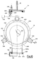
- An apparatus 20, generally designed for performing the treatment cycle shown in Figure 1, is shown, as a whole, in Figure 2 and in greater detail in Figures 3 and 4.
- This apparatus 20 comprises an autoclave chamber 22 resting by means of supports, such as columns 24 and 26, on a floor or base 28.
- the said autoclave chamber 22 comprises an entry door or hatch 30 of the type for example described and illustrated in Figures 11 to 15 of the Italian Patent Application No. 22155 A/89 filed on 27 October 1989 in the name of the same proprietor of the present Application.
- the said chamber 22 is also provided with an unloading connector 32 which can be rotated into two diametrically opposite positions: a first closed position where it is directed upwards and engaged with a lid 34 secured by means of a curved arm 36 to a wall of the chamber 22, and a second unloading position where it is connected to a duct 38 for conveying into a protected environment the treated plugs for further processing.
- an unloading connector 32 which can be rotated into two diametrically opposite positions: a first closed position where it is directed upwards and engaged with a lid 34 secured by means of a curved arm 36 to a wall of the chamber 22, and a second unloading position where it is connected to a duct 38 for conveying into a protected environment the treated plugs for further processing.
- the said chamber 22 is served by accessory equipment such as a steam generator 40, connected by means of ducts 42 and 44 to the chamber 22, a pneumatic machine 46 operated by a motor 48 and able to provide the said chamber 22 with the desired reduced pressure levels, a drive unit 50 provided with a coupler or magnetic coupling 52, for transmitting movement inside the chamber without the need for any opening through the walls of the said chamber, an air inlet 54 for introducing hot air or cold air, as required, inside the chamber, a pipe 56 for water and any detergents which, via a control valve 58 and an inlet duct 60, conveys said water and detergents into the said chamber 22, an emulsifier 62 discharging into the chamber 22 via an inlet duct 63, operated by a motor 64 and supplied both with silicone oil from a storage tank 66 via a control valve 68 and with water from a pipe 70 via a control valve 72, for providing the autoclave chamber 22 with silicone oil emulsion prepared in each case according to requirements.
- accessory equipment such as a steam
- All of the abovementioned accessory equipment is operated from a control console 76 containing a processor with its peripheral units and electromechanical equipment for enabling, for example via a multiple cable 78, full control and operation of the whole apparatus 20.
- a carriage 80 for supplying plugs to be treated inside the apparatus 20 comprises a platform 82 movable on wheels 84 and 86 in the directions indicated by a double arrow 88 and carrying a frame 90 supporting in a pivoted manner via hinges, such as the hinge 92 visible in Figure 2, a container 94 for moving plugs, for example from a warehouse or a plug production plant to the said apparatus 20, inside which it may be upturned with the aid of means such as a lever 96.
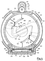
- the autoclave chamber 22 contains a rotating cylindrical basket 100 formed by two half-shells 102 and 104 connected together by means of two respective circular flanges 106 and 108, bolted together, the former of which is provided with a toothed rim 110 engaging with a gear wheel 112 in turn actuated by a pinion 114 accommodated inside a small sealed chamber 116 and connected to the said magnetic coupling 52 actuated by the drive unit 50.
- the autoclave chamber 22 is provided with a sealed internal wall 118 provided with heat-insulating lining layers 120 and connected at the front to a structure or frame 122 for retaining and supporting the entrance door 30 and ending at the rear in an opening 124 for unloading parts of the apparatus according to the invention.
- the circular inlet opening 136 in addition to admitting batches of plugs to be treated, accommodates in an axial direction at least a first pipe 138 for introducing water along with any washing detergents, equipped with a set of spraying nozzles 140 and connected to the duct 60 for introducing water and detergents.
- the opening 136 is able to accommodate, again in the axial direction, a second pipe 142 which is also provided with a set of spraying nozzles 144 and is connected to a duct 63 for introducing silicone-oil emulsion.
- the pipe 138 projects in cantilever fashion inside the basket 100 and is fixed to the sealed internal wall 118 by means of a fast-action fixing member 146 such as a bolted flange or, even better, a fast joint member.
- the pipe 142 also projects in cantilever fashion inside the basket 100 and is also fixed to the sealed internal wall 118 by means of a fixing member, such as a fast joint member 148.
- the cyldindrical basket 100 rests on two pairs of rollers 150 and 152 so as to be able to roll freely on the same when the toothed rim 110 is made to rotate, which pairs of rollers 150 and 152 pivotably hinged with brackets 154 and 156 are fixed to a frame 158 mounted on wheels 160 and 162 travelling on rails 164 and 166 which are in turn accommodated inside a niche or recess 168 connected to the said sealed internal wall 118 of the autoclave chamber 22.
- the frame 158 is then fixed in some way, for example by means of one or more bolts 170, to the said wall 118 so as to remain stationary, together with the basket 100, inside the autoclave chamber 22, while simple slackening of the bolt or bolts 170 is able to allow the entire frame 158 with the basket 100 above to be pulled out from the chamber 22.
- This operation is performed rather frequently after a certain number of plug treatment cycles in order to eliminate all the treatment residue (such as traces of silicone oil, residue material from the plugs and the like) which may be deposited on the walls of the basket 100 and on the wall 118 of the chamber 22.
- the upper steam duct 42 and the lower steam duct 44 are connected respectively to an upper steam distributor 172 and to a lower steam distributor 174 in the form of a perforated tubular loop which enables the steam to be conveyed in a substantially uniform manner throughout the chamber 22.
- the two helical members 126 and 128 are both provided with rounded internal edges 182 and 184, respectively, which on the convex side act as receiving surfaces so as to make the plugs 180 fall from the helical member 126, during rotation of basket 100 in the direction indicated by an arrow 186, across the said drum 100, causing them to pass through jets 188 produced by the nozzles 140 of the pipe 138 so as to ensure washing of the said plugs 180, or through similar jets from the nozzles 144 so as to ensure coating of the said plugs with silicone. Falling and mixing of the plugs 180 across the basket 100 also has the function, during sterilization when the entire basket is permeated by high-temperature steam, of turning over the said plugs and exposing them uniformly to the action of the steam.
- the concave side of the said internal edges 182 and 184 also collects and amasses the plugs 180 into piles 190 which are then conveyed towards the chutes 130 and 132 when the basket 100 is made to rotate in the direction of the arrow 192, passing at the highest point from one helical member 126 to the opposite helical member 128 until they reach the vicinity of the chutes 130 and 132 where they then begin to leave the basket 100 via the outlet opening 134.
- the plugs 180 during washing, fall in succession from the helical member 126, rolling over the rounded edge 182, pass through the jets 188 and are deposited on the internal wall of the basket 100, falling along the edge of the pile 190 so that the washing liquid of the jets 188 avoids most of the plugs of the pile 190 so that there is a minimum risk of redeposition of dirt removed from already-washed plugs accumulated in the pile 190.
- This results in satisfactory washing of the plugs 180 being achieved, with a smaller number of cycles, and hence in greater operating efficiency of the apparatus.
- it is sufficient to regulate the speed of rotation of the basket 100 in accordance with criteria which are well-known to experts in this particular art.
- the side wall of the basket 100 such as for example the half-shell 102, is provided with funnel shaped holes 194 which have, on the inside, a rounded lip 196 so that, when falling against, or rolling along a side wall, each plug 180 never encounters sharp edges, but merely sufficiently rounded lips, such as the lip 196 (see Figure 5A in this connection).
- the type of inlet door or hatch 30 preferred in this example of embodiment of the invention which, as already mentioned hereinabove, is similar to that described in the aforementioned Italian Patent Application No. 22155 A/89 and illustrated in Figures 11 to 15.
- the hatch 30 consists of a swing-door 198 fixed by means of hinges 200 and 202 rotatable about a spindle 204 mounted on two ball-bearing supports 206 and 208 movable inside diagonal slots 210, 212.
- the swing-door 198 is provided with means for anchoring to the door structure or frame 122, such as a left-hand right-angled bracket 214 fixed to the frame 122, a right-hand right-angled bracket 216 formed integrally with the said swing-door 198, the right-angled bracket 214 engaging with a corresponding left-hand side 218 of the swing-door 198 and the right-angled bracket 216 engaging with a corresponding counter-bracket (not shown) integral with the frame 122, as well as a bottom bracket 220 fixed to the frame 122, and a top right-angled bracket 222 formed integrally with the swing-door 198, the bottom right-angled bracket 220 engaging with a corresponding bottom side 224 of the swing-door and the top bracket 222 engaging with a top counter-bracket 226 formed integrally with the frame 122 (see Figure 3).
- the tightness of the hatch 30 is ensured by an emerging seal 228 (also shown in Figure 3) for example of the type described and claimed in Utility Model No. 189,131
- the procedure for opening the hatch 30 is identical to that illustrated in the aforementioned Patent Application, i.e. the ball-bearing supports 206 and 208 move along the slots 210 and 212, causing a translatory movement of the swing-door 198 in the direction of an arrow 230 and hence freeing the sides 218 and 224 of the said swing-door 198 from the right-angled brackets 214 and 220 fixed to the frame 122 and the right-angled brackets 216 and 222 from the corresponding counter-brackets fixed to the said frame 122 and subsequently the spindle 204 rotates in the direction of the arrow 232 so as to cause rotation and hence opening of the door 198.
- the hatch 30 is provided with an inspection port 236 making it possible, with suitable illumination, to see inside the basket 100 through the inlet opening 136.
- this inspection port 236 comprises a short tubular sleeve 238 terminating externally in a first flat circular flange 240 on which a second flat circular flange 242 rests, being fixed to the first flange by means of bolts 244 and pressing a glass plate 246 against the said first flange.
- An illumination apparatus 248 consisting of a lamp 250, provided with reflecting mirror 252 and possible control pushbutton 254, allows a proper lightning of the inside of the basket and its contents for a vision inspection thereof.
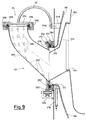
- the unloading connector 32 is formed by a tubular elbow 260 welded to a disc-shaped flange 262 which rests against a flat circumferential flange 264 having substantially the shape of a circular rim which is turn fixed to the sealed internal wall 118 of the autoclave chamber 22.
- the said flat flange 264 has mounted on it a certain number of circular segments (ideally three) 266, 268, 270 provided with a right-angled profile and fixed for example by means of bolts, such as the bolt 272, clamping and keeping joined together the two flanges 262 and 264.
- the external face of the flat circumferential flange 264 has formed in it a circular recess 274 designed to accommodate an emerging seal 276, preferably of the same type as that described in the aforementioned Utility Model No. 189,131, which produces a sealing action against the internal face of the disc-shaped flange 262 when a fluid under pressure, such as compressed air, is conveyed to the cavity 274 via a duct, such as the duct 278 illustrated in Figures 9 and 11.
- a fluid under pressure such as compressed air
- a lid 34 formed essentially by a circular disc 284 welded at the top to the curved arm 36 and provided with a circular recess 286, which is open on its lower face, for accommodating an emerging seal 288 which may be of the type described in the already mentioned Italian Utility Model No. 189,131, and which is made to emerge by the application of fluid under pressure, such as compressed air, via a duct 290 so as to press against a face 292 of an outlet mouth 294 of the elbow 260 in order to ensure a total sealing action between the disc 284 and the mouth 294.
- fluid under pressure such as compressed air
- the left-hand collar means 296 keeps the left-hand part of the disc 284 joined to the left-hand part of the mouth 294 as a result of its upper lip 304 resting against the upper face of the disc 284 and its lower lip 306 resting against a projecting lip 308 of the said mouth 294, while the right-hand collar means 298 keeps the right-hand part of the disc 284 joined to the right-hand part of the mouth 294 as a result of its upper lip 310 resting against the upper face of the disc 284 and its lower lip 312 resting against the projecting lip 308 of the mouth 294 and owing to the action of the weld 302. Obviously the pressing action of the emerging seal 288 completes the sealing effect obtained between the disc 284 and the mouth 294.
- Unloading of the pile 190 of treated plugs is performed, as illustrated in Figure 11, by means of a connecting funnel 334 which is inserted into the tubular elbow 260 and inside which the pile 190 of plugs flows when the basket 100 is made to rotate in the direction of the arrow 192 of Figure 6.
- the said pile 190 of plugs then flows in the direction of the arrow 336 of Figure 11, reaching other stations of a pharmaceutical plant which contains the apparatus according to the present invention.
- the said chamber 22 passes periodically from high pressures, which are due to the steam used for sterilization, to low pressures, which are due to the flash-evaporation drying procedure and, consequently, the disc-shaped flange 262 tends to move away from the fixed circumferential flange 264 and the tubular elbow 260 tends to straighten when a high pressure is applied inside the chamber 22, while the flange 262 tends to move towards the flange 264, compressing the seal 276, and the elbow 260 tends to become more curved when a reduced pressure is applied inside the chamber 22.
- the mouth 294 of the elbow 260 is not always located at exactly the same distance from the sealed wall 118 to which the lid 34 is fixed by means of the arm 36 and hence the curved shape shown in Figures 2, 3, 9 and 11 is preferred for the arm 36 so as to be able to compensate easily for those variations in distance between lid 34 and wall 118 which may occur during treatment of the plugs.
Landscapes
- Chemical & Material Sciences (AREA)
- Organic Chemistry (AREA)
- Chemical Kinetics & Catalysis (AREA)
- Apparatus For Disinfection Or Sterilisation (AREA)
- Drying Of Solid Materials (AREA)
Applications Claiming Priority (2)
| Application Number | Priority Date | Filing Date | Title |
|---|---|---|---|
| ITMI921522A IT1254981B (it) | 1992-06-19 | 1992-06-19 | Apparato di lavaggio e sterilizzazione di tappi di gomma, o simili impiegabili in confezioni farmaceutiche |
| ITMI921522 | 1992-06-19 |
Publications (1)
| Publication Number | Publication Date |
|---|---|
| EP0575005A1 true EP0575005A1 (de) | 1993-12-22 |
Family
ID=11363551
Family Applications (1)
| Application Number | Title | Priority Date | Filing Date |
|---|---|---|---|
| EP93201722A Withdrawn EP0575005A1 (de) | 1992-06-19 | 1993-06-16 | Vorrichtung zum Reinigen und Sterilisieren von Kunststoffstopfen oder dergleichen zur Verwendung in pharmazeutischen Behältern |
Country Status (3)
| Country | Link |
|---|---|
| US (1) | US5439655A (de) |
| EP (1) | EP0575005A1 (de) |
| IT (1) | IT1254981B (de) |
Cited By (14)
| Publication number | Priority date | Publication date | Assignee | Title |
|---|---|---|---|---|
| DE19922195A1 (de) * | 1999-05-12 | 2000-11-16 | Linde Tech Gase Gmbh | Reinigungsvorrichtung |
| EP1069153A1 (de) * | 1999-07-12 | 2001-01-17 | Daikyo Seiko, Ltd. | Herstellungverfahren für Gummistopfen |
| EP0878413B1 (de) * | 1997-05-09 | 2002-08-21 | Wolfgang Dipl.-Ing. Reinsberg | Verschliessbarer Behälter mit Schienen, Dichtungen, Stromzuführungen und Anschlüssen |
| ES2245530A1 (es) * | 2001-09-15 | 2006-01-01 | Alois Muller | Maquina para el tratamiento masivo de piezas industriales fabricadas en gran serie. |
| EP1707277A1 (de) * | 2005-03-31 | 2006-10-04 | Mutual Corporation | Verfahren und Vorrichtung zum Reinigen und Transportieren von Gummistopfen |
| WO2008136718A1 (en) | 2007-05-07 | 2008-11-13 | Sanciflex Ab | Apparatus for treating material comprising pressure vessel with drum rotatably arranged inside |
| US20100092652A1 (en) * | 2007-03-23 | 2010-04-15 | Kunitomo Kankyo Plant Co., Ltd. | Apparatus and method for treating organic waste and organic material obtained by the treatment method |
| CN102397846A (zh) * | 2011-12-05 | 2012-04-04 | 楚天科技股份有限公司 | 用于胶塞清洗机上的在位清洗灭菌装置 |
| CN102688864A (zh) * | 2012-05-22 | 2012-09-26 | 江苏华机环保设备有限责任公司 | 一种新型秸秆水洗器 |
| EP2762168A1 (de) | 2013-02-05 | 2014-08-06 | MOCOM S.r.L. | Autoklav zum Sterilisieren von Instrumenten |
| EP3072532A1 (de) | 2015-03-23 | 2016-09-28 | Icos Pharma S.p.A. | Fassungsbehälter für eine maschine zum waschen und / oder sterilisieren lose produkte |
| IT201700048057A1 (it) * | 2017-05-04 | 2018-11-04 | Last Tech S R L | Dosatore e procedimento per utilizzarlo. |
| EP3417884A1 (de) * | 2014-04-04 | 2018-12-26 | Icos Pharma S.p.A. | Sterilisiermaschine für lose produkte |
| CN112121201A (zh) * | 2020-09-30 | 2020-12-25 | 宁波方太厨具有限公司 | 一种消毒柜 |
Families Citing this family (18)
| Publication number | Priority date | Publication date | Assignee | Title |
|---|---|---|---|---|
| US7556767B2 (en) | 1997-12-17 | 2009-07-07 | Ethicon, Inc. | Integrated washing and sterilization process |
| US6818178B2 (en) * | 2001-08-16 | 2004-11-16 | Environmental Tectonics Corporation | Method for high vacuum sterilization of closures |
| KR100510680B1 (ko) * | 2003-03-31 | 2005-08-31 | 엘지전자 주식회사 | 증기분사식 드럼세탁기 |
| US7600402B2 (en) | 2003-11-04 | 2009-10-13 | Lg Electronics Inc. | Washing apparatus and control method thereof |
| US20050129889A1 (en) * | 2003-12-12 | 2005-06-16 | Edo Corporation, Fiber Science Division | Vessel and method for forming same |
| US8707861B2 (en) * | 2004-08-02 | 2014-04-29 | John Bean Technologies Corporation | Dry food pasteurization apparatus and method |
| CN1977078B (zh) * | 2005-03-16 | 2013-09-04 | Lg电子株式会社 | 使用蒸汽的洗衣机及控制该洗衣机的方法 |
| GB201001375D0 (en) * | 2010-01-28 | 2010-03-17 | Aerothermal Group Plc | Apparatus and process for treating municipal solid waste |
| CN103357620B (zh) * | 2013-07-09 | 2015-02-18 | 温州亚光机械制造有限公司 | 用于胶塞清洗机的内笼门自动启闭装置 |
| CN104889094A (zh) * | 2015-05-11 | 2015-09-09 | 成都中牧生物药业有限公司 | 一种全自动胶塞清洁设备 |
| CN104858170A (zh) * | 2015-05-11 | 2015-08-26 | 成都中牧生物药业有限公司 | 基于胶塞内壁清洁彻底的胶塞清洗机改进结构 |
| CN104888242B (zh) * | 2015-05-15 | 2018-08-21 | 楚天科技股份有限公司 | 一种法兰密封装置及脉动真空灭菌柜 |
| CA3085289A1 (en) | 2017-12-11 | 2019-06-20 | Glaxosmithkline Intellectual Property Development Limited | Modular aseptic production system |
| CN109125772B (zh) * | 2018-09-19 | 2024-03-26 | 江苏神农灭菌设备股份有限公司 | 旋转式胶塞清洗灭菌柜中灭菌筒体的驱动装置 |
| CN109107963B (zh) * | 2018-09-19 | 2024-03-12 | 江苏神农灭菌设备股份有限公司 | 一种用于清洗胶塞的旋转动态灭菌柜 |
| CN114012566B (zh) * | 2021-10-07 | 2022-09-06 | 张文鹏 | 一种新能源汽车轮毅打磨装置 |
| CN114042688B (zh) * | 2021-11-17 | 2023-12-05 | 丰都县中医院 | 一种医用球形草药淘洗无污染一体机 |
| CN116475148B (zh) * | 2023-03-31 | 2023-12-19 | 江苏博生医用新材料股份有限公司 | 一种药品密封塞清洗灭菌装置 |
Citations (6)
| Publication number | Priority date | Publication date | Assignee | Title |
|---|---|---|---|---|
| US3487840A (en) * | 1967-05-22 | 1970-01-06 | Waukee Eng Co | Apparatus for cleaning articles |
| DE3011517A1 (de) * | 1980-03-25 | 1981-10-01 | Werner 4006 Erkrath Rütten | Kontinuierlich arbeitende hochdruck-wasch- und spuelanlage |
| DE3248555A1 (de) * | 1982-12-29 | 1984-07-12 | Anton Huber Gmbh & Co Kg, 8050 Freising | Maschine zum reinigen empfindlicher kleinteile, wie pharmazeutischer verschlusselemente |
| US4719933A (en) * | 1986-12-08 | 1988-01-19 | Warren M. Jackson, Inc. | Machine for washing particulate workpieces |
| DE3841930A1 (de) * | 1988-12-13 | 1990-06-21 | Pta Pharma Techn Apparatebau G | Vorrichtung und verfahren zum reinigen, sterilisieren und trocknen kleiner gegenstaende, insbesondere pharmazeutischer verschluesse |
| EP0460344A2 (de) * | 1990-06-05 | 1991-12-11 | Dietwart Völpel | Einrichtung zum Reinigen und Sterilisieren von Gegenständen, insbesondere pharmazeutischen Verschlusselementen |
Family Cites Families (13)
| Publication number | Priority date | Publication date | Assignee | Title |
|---|---|---|---|---|
| US1204357A (en) * | 1915-01-13 | 1916-11-07 | Eugene D Jefferson | Apparatus for treating fibrous material. |
| US2861446A (en) * | 1953-08-20 | 1958-11-25 | Petterson Olof Holger | Machines for treating or washing clothes and the like |
| US2884287A (en) * | 1956-02-27 | 1959-04-28 | Holderbank Cement | Support arrangement |
| US3138167A (en) * | 1963-06-18 | 1964-06-23 | Sprout Waldron & Co Inc | Mixer for feeds and the like |
| GB1161209A (en) * | 1966-05-12 | 1969-08-13 | Maharaj Krishen Mehta | Apparatus for Washing Particles such as Capsules. |
| US3506021A (en) * | 1966-10-10 | 1970-04-14 | Rietz Mfg Co | Discharge apparatus for processing equipment |
| DE2125102A1 (de) * | 1971-05-19 | 1972-11-30 | Anton Huber Gmbh & Co Kg, 8050 Freising | Verfahren und Einrichtung zum Reinigen einer Anzahl kleiner Gegenstände |
| US3744402A (en) * | 1971-12-16 | 1973-07-10 | Welding And Steel Fabrication | Pressure vessel for uniformly treating articles in batch form |
| DE7441076U (de) * | 1974-12-10 | 1975-10-09 | Engelhardt & Foerster | Du rchlauf waschmaschine |
| US4829792A (en) * | 1987-07-27 | 1989-05-16 | Brent Keith M | Double drum batch washing machine |
| JPH0665395B2 (ja) * | 1988-09-30 | 1994-08-24 | 成太郎 西林 | 連続洗浄装置 |
| US5223229A (en) * | 1990-07-19 | 1993-06-29 | Midmark Corporation | Sterilizing apparatus having automatically actuated door |
| US5211039A (en) * | 1991-03-12 | 1993-05-18 | Pellerin Milnor Corporation | Continuous batch type washing machine |
-
1992
- 1992-06-19 IT ITMI921522A patent/IT1254981B/it active IP Right Grant
-
1993
- 1993-06-15 US US08/076,758 patent/US5439655A/en not_active Expired - Fee Related
- 1993-06-16 EP EP93201722A patent/EP0575005A1/de not_active Withdrawn
Patent Citations (6)
| Publication number | Priority date | Publication date | Assignee | Title |
|---|---|---|---|---|
| US3487840A (en) * | 1967-05-22 | 1970-01-06 | Waukee Eng Co | Apparatus for cleaning articles |
| DE3011517A1 (de) * | 1980-03-25 | 1981-10-01 | Werner 4006 Erkrath Rütten | Kontinuierlich arbeitende hochdruck-wasch- und spuelanlage |
| DE3248555A1 (de) * | 1982-12-29 | 1984-07-12 | Anton Huber Gmbh & Co Kg, 8050 Freising | Maschine zum reinigen empfindlicher kleinteile, wie pharmazeutischer verschlusselemente |
| US4719933A (en) * | 1986-12-08 | 1988-01-19 | Warren M. Jackson, Inc. | Machine for washing particulate workpieces |
| DE3841930A1 (de) * | 1988-12-13 | 1990-06-21 | Pta Pharma Techn Apparatebau G | Vorrichtung und verfahren zum reinigen, sterilisieren und trocknen kleiner gegenstaende, insbesondere pharmazeutischer verschluesse |
| EP0460344A2 (de) * | 1990-06-05 | 1991-12-11 | Dietwart Völpel | Einrichtung zum Reinigen und Sterilisieren von Gegenständen, insbesondere pharmazeutischen Verschlusselementen |
Cited By (26)
| Publication number | Priority date | Publication date | Assignee | Title |
|---|---|---|---|---|
| EP0878413B1 (de) * | 1997-05-09 | 2002-08-21 | Wolfgang Dipl.-Ing. Reinsberg | Verschliessbarer Behälter mit Schienen, Dichtungen, Stromzuführungen und Anschlüssen |
| US6821356B1 (en) | 1999-05-12 | 2004-11-23 | Linde Aktiengesellschaft | Cleaning device and method for cleaning, using liquid and/or supercritical gases |
| DE19922195A1 (de) * | 1999-05-12 | 2000-11-16 | Linde Tech Gase Gmbh | Reinigungsvorrichtung |
| EP1069153A1 (de) * | 1999-07-12 | 2001-01-17 | Daikyo Seiko, Ltd. | Herstellungverfahren für Gummistopfen |
| ES2245530A1 (es) * | 2001-09-15 | 2006-01-01 | Alois Muller | Maquina para el tratamiento masivo de piezas industriales fabricadas en gran serie. |
| EP1707277A1 (de) * | 2005-03-31 | 2006-10-04 | Mutual Corporation | Verfahren und Vorrichtung zum Reinigen und Transportieren von Gummistopfen |
| US20100092652A1 (en) * | 2007-03-23 | 2010-04-15 | Kunitomo Kankyo Plant Co., Ltd. | Apparatus and method for treating organic waste and organic material obtained by the treatment method |
| US8365433B2 (en) * | 2007-03-23 | 2013-02-05 | Kunitomo Kankyo Plant Co., Ltd. | Apparatus and method for treating organic waste and organic material obtained by the treatment method |
| WO2008136718A1 (en) | 2007-05-07 | 2008-11-13 | Sanciflex Ab | Apparatus for treating material comprising pressure vessel with drum rotatably arranged inside |
| NO341539B1 (no) * | 2007-05-07 | 2017-12-04 | Sanciflex Ab | Anordning for behandling av materiale omfattende en trykkbeholder med en deri roterbart anordnet trommel |
| US8747771B2 (en) | 2007-05-07 | 2014-06-10 | Sanciflex Ab | Apparatus for treating material comprising pressure vessel with drum rotatable arranged inside |
| EP2148739A4 (de) * | 2007-05-07 | 2013-01-02 | Sanciflex Ab | Vorrichtung zur behandlung von material mit einem druckgefäss mit drehbar darin angeordneter trommel |
| EP2148739A1 (de) * | 2007-05-07 | 2010-02-03 | Sanciflex AB | Vorrichtung zur behandlung von material mit einem druckgefäss mit drehbar darin angeordneter trommel |
| US8431085B2 (en) | 2007-05-07 | 2013-04-30 | Sanciflex Ab | Apparatus for treating material comprising pressure vessel with drum rotatable arranged inside |
| CN102397846B (zh) * | 2011-12-05 | 2013-11-20 | 楚天科技股份有限公司 | 用于胶塞清洗机上的在位清洗灭菌装置 |
| CN102397846A (zh) * | 2011-12-05 | 2012-04-04 | 楚天科技股份有限公司 | 用于胶塞清洗机上的在位清洗灭菌装置 |
| CN102688864A (zh) * | 2012-05-22 | 2012-09-26 | 江苏华机环保设备有限责任公司 | 一种新型秸秆水洗器 |
| EP2762168A1 (de) | 2013-02-05 | 2014-08-06 | MOCOM S.r.L. | Autoklav zum Sterilisieren von Instrumenten |
| ITBO20130050A1 (it) * | 2013-02-05 | 2014-08-06 | Mocom Srl | Autoclave per la sterilizzazione di strumenti |
| CN103961729A (zh) * | 2013-02-05 | 2014-08-06 | Mocom有限责任公司 | 用于消毒器械的高压灭菌器 |
| DE202014105174U1 (de) | 2013-02-05 | 2014-11-19 | Mocom S.R.L. | Autoklav zum Sterilisieren von Instrumenten |
| EP3417884A1 (de) * | 2014-04-04 | 2018-12-26 | Icos Pharma S.p.A. | Sterilisiermaschine für lose produkte |
| EP3072532A1 (de) | 2015-03-23 | 2016-09-28 | Icos Pharma S.p.A. | Fassungsbehälter für eine maschine zum waschen und / oder sterilisieren lose produkte |
| IT201700048057A1 (it) * | 2017-05-04 | 2018-11-04 | Last Tech S R L | Dosatore e procedimento per utilizzarlo. |
| CN112121201A (zh) * | 2020-09-30 | 2020-12-25 | 宁波方太厨具有限公司 | 一种消毒柜 |
| CN112121201B (zh) * | 2020-09-30 | 2021-10-12 | 宁波方太厨具有限公司 | 一种消毒柜 |
Also Published As
| Publication number | Publication date |
|---|---|
| US5439655A (en) | 1995-08-08 |
| ITMI921522A0 (it) | 1992-06-19 |
| ITMI921522A1 (it) | 1993-12-19 |
| IT1254981B (it) | 1995-10-11 |
Similar Documents
| Publication | Publication Date | Title |
|---|---|---|
| US5439655A (en) | Apparatus for washing and sterilizing rubber plugs or the like which may be used in pharmaceutical containers | |
| JP3255923B2 (ja) | 滅菌バイアル充填装置 | |
| JP3298014B2 (ja) | 工業用洗浄設備 | |
| US3736948A (en) | Washing and sanitizing apparatus for carts such as hospital carts | |
| US7024988B2 (en) | Plant for the continuous processing and packing of meat products | |
| US4080974A (en) | Bottle cleaning apparatus | |
| US5425385A (en) | Rotary washer spraying system | |
| JP2820761B2 (ja) | 小型物品の洗浄殺菌装置 | |
| JPH11193009A (ja) | キャップの殺菌洗浄装置 | |
| US3166082A (en) | Industrial parts washer | |
| WO1998001344A1 (en) | Sterilization device and method for sterilizing objects | |
| US3097658A (en) | Rotary jar washer | |
| US6158450A (en) | Epicycloidic industrial cleaning system | |
| US6035872A (en) | Rotary distributor rotating apparatus for handling of objects, in particular containers, with a revolving joint for the transport of fluid between a stationary assembly and a rotating assembly | |
| US4958649A (en) | Apparatus for treating articles with a gaseous and/or liquid medium | |
| CN2472722Y (zh) | 全自动胶塞清洗灭菌器 | |
| JP2560115B2 (ja) | マットレス、ふとん等の洗浄装置 | |
| CA2235732A1 (en) | Rotary distributor rotating apparatus for the handling of objects, in particular containers, with a revolving joint for the transport of fluid between a support assembly and a rotating assembly | |
| JP3915174B2 (ja) | 電磁弁のエア排気装置 | |
| JPH0725376B2 (ja) | 容器蓋の滅菌方法及び装置 | |
| JPH11277017A (ja) | ロータリ式洗びん機のロータリバルブ押圧装置およびロータリバルブ洗浄装置 | |
| JP3022456B2 (ja) | 固形物食品用蒸煮釜及び蒸煮装置 | |
| JP3915172B2 (ja) | ノズル洗浄装置 | |
| JPH0334308Y2 (de) | ||
| US4560282A (en) | Apparatus for mixing and granulating powdery substances with a sifting device attached by means of a valve closure |
Legal Events
| Date | Code | Title | Description |
|---|---|---|---|
| PUAI | Public reference made under article 153(3) epc to a published international application that has entered the european phase |
Free format text: ORIGINAL CODE: 0009012 |
|
| AK | Designated contracting states |
Kind code of ref document: A1 Designated state(s): AT BE CH DE DK ES FR GB GR IE IT LI LU MC NL PT SE |
|
| 17P | Request for examination filed |
Effective date: 19940613 |
|
| 17Q | First examination report despatched |
Effective date: 19950314 |
|
| GRAH | Despatch of communication of intention to grant a patent |
Free format text: ORIGINAL CODE: EPIDOS IGRA |
|
| GRAH | Despatch of communication of intention to grant a patent |
Free format text: ORIGINAL CODE: EPIDOS IGRA |
|
| STAA | Information on the status of an ep patent application or granted ep patent |
Free format text: STATUS: THE APPLICATION HAS BEEN WITHDRAWN |
|
| 18W | Application withdrawn |
Withdrawal date: 19960612 |