EP0572301A1 - Tiefziehvorrichtung zum Ziehen von blattförmigem Material in einer elastischen Verformungsmatrize - Google Patents
Tiefziehvorrichtung zum Ziehen von blattförmigem Material in einer elastischen Verformungsmatrize Download PDFInfo
- Publication number
- EP0572301A1 EP0572301A1 EP93401288A EP93401288A EP0572301A1 EP 0572301 A1 EP0572301 A1 EP 0572301A1 EP 93401288 A EP93401288 A EP 93401288A EP 93401288 A EP93401288 A EP 93401288A EP 0572301 A1 EP0572301 A1 EP 0572301A1
- Authority
- EP
- European Patent Office
- Prior art keywords
- cushion
- elastic element
- retention tank
- chamber
- elastic
- Prior art date
- Legal status (The legal status is an assumption and is not a legal conclusion. Google has not performed a legal analysis and makes no representation as to the accuracy of the status listed.)
- Granted
Links
- 239000000463 material Substances 0.000 title claims abstract description 21
- 229920001971 elastomer Polymers 0.000 claims abstract description 10
- 239000013013 elastic material Substances 0.000 claims abstract description 7
- 239000000806 elastomer Substances 0.000 claims abstract description 7
- 230000014759 maintenance of location Effects 0.000 claims description 20
- 230000001105 regulatory effect Effects 0.000 claims description 19
- 238000006073 displacement reaction Methods 0.000 claims description 5
- 238000007493 shaping process Methods 0.000 claims description 5
- 239000011159 matrix material Substances 0.000 claims description 4
- 239000012528 membrane Substances 0.000 claims description 4
- 239000002184 metal Substances 0.000 abstract description 4
- 230000002093 peripheral effect Effects 0.000 description 6
- 238000004519 manufacturing process Methods 0.000 description 4
- 238000010521 absorption reaction Methods 0.000 description 3
- 238000010438 heat treatment Methods 0.000 description 3
- 239000002131 composite material Substances 0.000 description 2
- 230000006835 compression Effects 0.000 description 2
- 238000007906 compression Methods 0.000 description 2
- 230000000694 effects Effects 0.000 description 2
- 230000000750 progressive effect Effects 0.000 description 2
- RRHGJUQNOFWUDK-UHFFFAOYSA-N Isoprene Chemical compound CC(=C)C=C RRHGJUQNOFWUDK-UHFFFAOYSA-N 0.000 description 1
- 229910000831 Steel Inorganic materials 0.000 description 1
- 238000006243 chemical reaction Methods 0.000 description 1
- 239000000470 constituent Substances 0.000 description 1
- 230000004048 modification Effects 0.000 description 1
- 238000012986 modification Methods 0.000 description 1
- 239000004033 plastic Substances 0.000 description 1
- 229920001195 polyisoprene Polymers 0.000 description 1
- 229920002379 silicone rubber Polymers 0.000 description 1
- 239000010959 steel Substances 0.000 description 1
- 230000008961 swelling Effects 0.000 description 1
Images
Classifications
-
- B—PERFORMING OPERATIONS; TRANSPORTING
- B21—MECHANICAL METAL-WORKING WITHOUT ESSENTIALLY REMOVING MATERIAL; PUNCHING METAL
- B21D—WORKING OR PROCESSING OF SHEET METAL OR METAL TUBES, RODS OR PROFILES WITHOUT ESSENTIALLY REMOVING MATERIAL; PUNCHING METAL
- B21D22/00—Shaping without cutting, by stamping, spinning, or deep-drawing
- B21D22/10—Stamping using yieldable or resilient pads
-
- Y—GENERAL TAGGING OF NEW TECHNOLOGICAL DEVELOPMENTS; GENERAL TAGGING OF CROSS-SECTIONAL TECHNOLOGIES SPANNING OVER SEVERAL SECTIONS OF THE IPC; TECHNICAL SUBJECTS COVERED BY FORMER USPC CROSS-REFERENCE ART COLLECTIONS [XRACs] AND DIGESTS
- Y10—TECHNICAL SUBJECTS COVERED BY FORMER USPC
- Y10T—TECHNICAL SUBJECTS COVERED BY FORMER US CLASSIFICATION
- Y10T29/00—Metal working
- Y10T29/49—Method of mechanical manufacture
- Y10T29/49805—Shaping by direct application of fluent pressure
Definitions
- the present invention relates to a device for stamping sheet materials on a forming matrix of elastic material.
- FR-A-2 641 217 discloses a device for stamping sheet materials, of the type comprising a cushion made of an elastic material housed in a retention tank, means for preforming a sheet blank, constituted by an external slide carrying an upper blank holder and means for definitive forming of said sheet blank constituted by a central slide acting on a plunger.
- This device also includes means for absorbing the excess volume of the elastic cushion relative to that determined by the surface of the finished part to be obtained.
- This device allows the stamping of a sheet material, in particular of a material with low elongation which may in particular be a metal sheet, for example steel.
- This device is not limited to the stamping of metal sheets, but can be applied to plastic materials and to any other composite material.
- the cushion of elastic material can be a composite support consisting of a substantially parallelepipedic mass based on a silicone elastomer, of low Shore hardness, possibly covered on its upper face, and on all and part of its lateral faces d '' a relatively thin envelope made of a more resistant and harder material.
- the blank holder applied to the peripheral part of the sheet blank causes the mass of the elastic cushion to creep to deform the central part of said sheet blank, while giving it, at the end of the preforming step, a surface substantially equal to the surface of the part to be obtained.
- the descent of the plunger for the final shaping of the sheet blank causes an increase in pressure in the cushion and a difference in volume in said cushion, between the preforming step and the shaping step, which it is necessary to compensate in order avoid an increase in pressure in the cushion.
- the device according to FR-A-2 641 217 comprises means for absorbing the excess volume of the elastic cushion generated during the application of the plunger.
- absorption means can be moved during the final forming of the part and this movement is regulated by a regulating member constituted for example by a multi-blade brake, or a spring or even a jack.
- This known device makes it possible to absorb large, constant and defined volume differences during the first press cycle for a geometry of the parts to be formed and at a given temperature.
- this device has the drawback of not responding to the problems of a progressive, even small, increase in volume of the cushion.
- This increase can be due to variations in the physical characteristics of the material constituting the cushion, such as for example a continuous heating of several tens of degrees generated by the deformation of the cushion under the action of the upper blank holder whose stroke can represent 20%. of the empty height of the cushion during the production of parts with a high press rate, i.e. greater at about ten cycles per minute.
- the object of the invention is the manufacture of parts with a press operating at a high rate without requiring a modification of the setting of said press during the forming operations.
- the present invention therefore relates to a device for stamping sheet materials, of the type comprising a matrix formed by a cushion made of an elastic material, such as for example an elastomer, housed in a retention tank, means for preforming a sheet blank, constituted by an external slide carrying an upper hold-down, means for definitive forming of said sheet blank, constituted by a central slide acting on a plunger and a first means of absorbing the excess volume of the cushion relative to to that determined by the surface of the finished part to be obtained during the definitive forming of said part, characterized in that it comprises at least one second means of compensating for the excess volume of the cushion due to variations in the physical characteristics of the constituent material said cushion during preforming and final forming of said part.
- a device for stamping sheet materials of the type comprising a matrix formed by a cushion made of an elastic material, such as for example an elastomer, housed in a retention tank, means for preforming a sheet blank, constituted by an external slide carrying an upper hold-down, means for
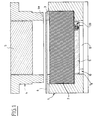
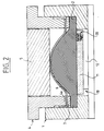
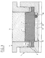
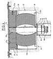
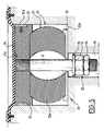
- the stamping device shown in Figs. 1 to 3 comprises a tank 1, the central part of which constitutes a housing for a matrix formed by a cushion 2 made of an elastic material, such as for example an elastomer.
- a frame 3 On the upper face of the elastic cushion 2 is disposed a frame 3 with a closed contour which constitutes a lower peripheral blank holder and which substantially follows the contour of the internal housing of the container 1 so as to be able to penetrate into said housing when the room.
- the stamping device comprises a body 4 carried by an external slide, not shown, and the lower part of which constitutes an upper peripheral blank holder 4a.
- the upper peripheral blank holder 4a has external dimensions slightly smaller than the outline of the internal housing of the container 1 so as to cooperate with the frame 3 and to penetrate into said housing.
- the body 4 has a central well inside which a plunger 5 penetrates, the underside of which constitutes an imprint corresponding to the profile of the finished part to be obtained.
- the device also comprises a first means 10 for absorbing the excess volume of the elastic cushion 2 generated by the application of the plunger 5 by compared to that determined by the surface of the finished part to be obtained during the definitive forming of said part.
- This means 10 is constituted, in this embodiment, by a piston 11 movable vertically constituting the bottom of the retention tank 1, which has for this purpose a central opening la.
- the piston 11 has its upper surface applied against the elastic cushion 2 and cooperates with a regulating member 12 for the movement of said piston.
- This regulating member 12 shown diagrammatically in FIGS. 1 to 3 is constituted for example by a multi-blade brake, or a spring or even a jack.
- the body 4 is lowered by means of the external slide, not shown, from the press, so that the upper blank holder 4a comes into contact with the sheet blank 6 whose peripheral zone is progressively clamped between the lower blank holder 3 and the upper blank holder 4a to avoid its scalloping.
- the upper blank holder 4a compresses the elastic cushion 2 by reaction.
- the swelling of the central part of the sheet blank 6 is limited by the bottom of the plunger 5 in order to avoid uncontrolled deformations.
- the regulating member 12 prevents the displacement of the movable piston 11 under the effect of the pressure exerted in the elastic cushion 2 and, consequently, prevents said elastic cushion from creeping towards the bottom.
- the plunger 5 descends to its low position and controls the final forming of the central part of the sheet blank 6 preformed during the previous operation.
- the regulating member 12 ensures the adjustment of the displacement of the piston 11 and, therefore, makes it possible to absorb the excess volume of the elastic cushion 2 generated by the application of the plunger 5.
- the pressure generated in the cushion is maintained at an adjustment value by automatic compensation for the excess volume of said elastic cushion.
- the device comprises at least a second means 20 for compensating for the excess volume of the elastic cushion 2.
- This compensation means is arranged in a wall of the retention tank 1 and for example in the movable piston 11 as shown in FIGS. 1 to 3.
- the compensation means 20 comprises, on the one hand, at least one sliding member 21 housed in a chamber 22 opening into the retention tank 1 and intended to cooperate with the elastic cushion 2 and, on the other hand, a regulating member 23 for the displacement of the sliding member 21, interposed between said sliding member 21 and the bottom 22a of the chamber 22.
- Chamber 22 can be open on the corresponding wall of the retention tank 1 or closed at the level of said wall by an elastic membrane 24 so as to seal the elastic cushion 2 relative to the device.
- the sliding member 21 is formed by a substantially flat sole having a face 21a flush with the corresponding wall of the retention tank 1 and comprising at its periphery at least one shoe 25 for guiding said sole 21 in the chamber 22.
- These pads are made of a material having good resistance to friction and are fixed in periphery of said sole 21 by means of screws 25a.
- the chamber 22 is extended by a recess 26.
- the regulating member 23 is formed by an elastic element 23a which cooperates with a means 30 for prestressing said elastic element.
- the means 30 for prestressing the elastic element 23a is formed by a rod 31 subject to said elastic element 23a and for example passing through this elastic element 23a and of which a first end 31a is connected to the sole 21, for example by a thread , and a second end 31b of which is provided with an adjustment nut 32 bearing on a plate 33 interposed between the elastic element 23a and the bottom 22a of the chamber 22.
- a washer 34 is placed between the plate 33 and the adjusting nut 32 and this adjusting nut 32 is blocked by a lock nut 35.
- the adjusting nut 32 and the counter nut 35 are disposed in the recess 26.
- the elastic element 23a can be formed for example by a rubber or elastomer block or by a spring or even by a gas spring.
- the regulating member 23 can be formed by a hydraulic system connected to an accumulator for adjusting the pressure or by a pneumatic system.
- This regulating member 23 regulates the movement of the sliding member 21 which has a given stroke whose extreme positions correspond to a minimum determined pressure and to a maximum determined pressure of the material constituting the elastic cushion 2.
- the compensation means thus described makes it possible to obtain an automatic adjustment of the pressure and of the volume of the elastic cushion 2 as the press operates.
- the stamping device may include one or more compensation means placed on a part of the bottom of the retention tank or on one of its side walls.
- the means for compensating for the excess volume of the cushion due to variations in the physical characteristics of the material constituting said cushion can be placed at the bottom of the retention tank or at one of its side walls.
Landscapes
- Engineering & Computer Science (AREA)
- Mechanical Engineering (AREA)
- Shaping Metal By Deep-Drawing, Or The Like (AREA)
- Presses And Accessory Devices Thereof (AREA)
Applications Claiming Priority (2)
| Application Number | Priority Date | Filing Date | Title |
|---|---|---|---|
| FR9206502 | 1992-05-27 | ||
| FR9206502A FR2691653B1 (fr) | 1992-05-27 | 1992-05-27 | Dispositif d'emboutissage de matériaux en feuille sur une matrice de formage en matériau élastique. |
Publications (2)
| Publication Number | Publication Date |
|---|---|
| EP0572301A1 true EP0572301A1 (de) | 1993-12-01 |
| EP0572301B1 EP0572301B1 (de) | 1996-07-24 |
Family
ID=9430242
Family Applications (1)
| Application Number | Title | Priority Date | Filing Date |
|---|---|---|---|
| EP93401288A Expired - Lifetime EP0572301B1 (de) | 1992-05-27 | 1993-05-18 | Tiefziehvorrichtung zum Ziehen von blattförmigem Material in einer elastischen Verformungsmatrize |
Country Status (7)
| Country | Link |
|---|---|
| US (1) | US5361617A (de) |
| EP (1) | EP0572301B1 (de) |
| JP (1) | JPH07275962A (de) |
| CA (1) | CA2096461A1 (de) |
| DE (1) | DE69303773T2 (de) |
| ES (1) | ES2090906T3 (de) |
| FR (1) | FR2691653B1 (de) |
Cited By (3)
| Publication number | Priority date | Publication date | Assignee | Title |
|---|---|---|---|---|
| EP0739663A3 (de) * | 1995-04-24 | 1997-08-27 | Trumpf Gmbh & Co | Bearbeitungsmaschine zum Umformen von Werkstücken |
| EP0888833A1 (de) * | 1997-07-04 | 1999-01-07 | Humard Automation SA | Verfahren und Vorrichtung zum unterschiedlichen und/oder nacheinanderfolgenden Stanzen in mindestens zwei unterschiedlichen Richtungen |
| CN103331935A (zh) * | 2013-06-23 | 2013-10-02 | 苏州腾行精密模具有限公司 | 一种对称孔位冲模模具 |
Families Citing this family (10)
| Publication number | Priority date | Publication date | Assignee | Title |
|---|---|---|---|---|
| JP2595448B2 (ja) * | 1993-07-14 | 1997-04-02 | 日本製紙株式会社 | パルプモールド型の製造方法 |
| FR2715335B1 (fr) * | 1994-01-21 | 1996-04-05 | Lorraine Laminage | Dispositif d'emboutissage d'un flan de tôle. |
| KR100284270B1 (ko) * | 1998-09-23 | 2001-03-02 | 김태선 | 형틀과합성고무판재를이용한금속판재의입체무늬형성용가압성형장치및그방법 |
| DE10016804B4 (de) * | 2000-04-05 | 2004-11-11 | Thyssenkrupp Stahl Ag | Verfahren und Vorrichtung zum Herstellen von Bauteilen aus einer tiefziehbaren Platine |
| US6233989B1 (en) | 2000-10-13 | 2001-05-22 | Changing Paradigms, Llc | Method and apparatus for stamping a metal sheet with an apertured design having rolled edges |
| WO2012151416A1 (en) * | 2011-05-03 | 2012-11-08 | Kairis Paul R | Cover for striking device for percussion instrument |
| DE202012003953U1 (de) | 2012-04-20 | 2012-07-13 | Michael Konrath | Anschlagstock |
| CN105013918A (zh) * | 2015-07-02 | 2015-11-04 | 奇瑞汽车股份有限公司 | 复杂型面板材拉延模及其控制方法 |
| CN111842637B (zh) * | 2020-07-03 | 2023-07-14 | 北京航星机器制造有限公司 | 一种钛合金深腔构件复合成形模具及成形方法 |
| CN116372022A (zh) * | 2023-02-20 | 2023-07-04 | 江铃汽车股份有限公司 | 一种拉延模具及其控制方法 |
Citations (3)
| Publication number | Priority date | Publication date | Assignee | Title |
|---|---|---|---|---|
| FR2462262A1 (fr) * | 1979-07-31 | 1981-02-13 | Bretagne Atel Chantiers | Presse a emboutir |
| EP0165133A1 (de) * | 1984-05-17 | 1985-12-18 | Sollac | Verfahren und Vorrichtung zum Formstanzen einer Metallplatte |
| FR2641217A1 (fr) * | 1988-12-30 | 1990-07-06 | Isoform | Procede et dispositif d'emboutissage de materiaux en feuille sur une matrice de formage elastique |
Family Cites Families (2)
| Publication number | Priority date | Publication date | Assignee | Title |
|---|---|---|---|---|
| FR2590814B1 (fr) * | 1985-12-04 | 1988-02-26 | Usinor | Procede et dispositif d'emboutissage de toles a faible allongement |
| SU1683841A1 (ru) * | 1989-01-03 | 1991-10-15 | Научно-исследовательский институт средств автоматизации | Устройство дл штамповки эластичной средой |
-
1992
- 1992-05-27 FR FR9206502A patent/FR2691653B1/fr not_active Expired - Fee Related
-
1993
- 1993-05-18 CA CA002096461A patent/CA2096461A1/fr not_active Abandoned
- 1993-05-18 ES ES93401288T patent/ES2090906T3/es not_active Expired - Lifetime
- 1993-05-18 DE DE69303773T patent/DE69303773T2/de not_active Expired - Fee Related
- 1993-05-18 EP EP93401288A patent/EP0572301B1/de not_active Expired - Lifetime
- 1993-05-25 US US08/066,660 patent/US5361617A/en not_active Expired - Fee Related
- 1993-05-27 JP JP5126204A patent/JPH07275962A/ja not_active Withdrawn
Patent Citations (3)
| Publication number | Priority date | Publication date | Assignee | Title |
|---|---|---|---|---|
| FR2462262A1 (fr) * | 1979-07-31 | 1981-02-13 | Bretagne Atel Chantiers | Presse a emboutir |
| EP0165133A1 (de) * | 1984-05-17 | 1985-12-18 | Sollac | Verfahren und Vorrichtung zum Formstanzen einer Metallplatte |
| FR2641217A1 (fr) * | 1988-12-30 | 1990-07-06 | Isoform | Procede et dispositif d'emboutissage de materiaux en feuille sur une matrice de formage elastique |
Cited By (3)
| Publication number | Priority date | Publication date | Assignee | Title |
|---|---|---|---|---|
| EP0739663A3 (de) * | 1995-04-24 | 1997-08-27 | Trumpf Gmbh & Co | Bearbeitungsmaschine zum Umformen von Werkstücken |
| EP0888833A1 (de) * | 1997-07-04 | 1999-01-07 | Humard Automation SA | Verfahren und Vorrichtung zum unterschiedlichen und/oder nacheinanderfolgenden Stanzen in mindestens zwei unterschiedlichen Richtungen |
| CN103331935A (zh) * | 2013-06-23 | 2013-10-02 | 苏州腾行精密模具有限公司 | 一种对称孔位冲模模具 |
Also Published As
| Publication number | Publication date |
|---|---|
| DE69303773T2 (de) | 1997-03-20 |
| FR2691653A1 (fr) | 1993-12-03 |
| FR2691653B1 (fr) | 1994-08-26 |
| JPH07275962A (ja) | 1995-10-24 |
| CA2096461A1 (fr) | 1993-11-28 |
| EP0572301B1 (de) | 1996-07-24 |
| ES2090906T3 (es) | 1996-10-16 |
| DE69303773D1 (de) | 1996-08-29 |
| US5361617A (en) | 1994-11-08 |
Similar Documents
| Publication | Publication Date | Title |
|---|---|---|
| EP0572301B1 (de) | Tiefziehvorrichtung zum Ziehen von blattförmigem Material in einer elastischen Verformungsmatrize | |
| EP0376809B1 (de) | Verfahren und Vorrichtung zum Tiefziehen von Blattmaterialien auf einer Matrize von elastischer Form | |
| EP0664168B1 (de) | Vorrichtung zum Tiefziehen eines Blechzuschnittes | |
| EP0376808B1 (de) | Verfahren und Vorrichtung zum Tiefziehen von Blattmaterialien mit einem deformierbaren Stempel unter einem Tauchkolben | |
| EP0435722A1 (de) | Verfahren und Vorrichtung zum Formen eines Blechzuschnittes insbesondere zur Herstellung einer Maske für eine Kathodenstrahlröhre | |
| EP0380894B1 (de) | Vorrichtung zum Tiefziehen von Blattmaterialien | |
| EP0541427A1 (de) | Vorrichtung zum Formstanzen von Blattmaterialien, insbesondere von Blechplättchen | |
| KR102018916B1 (ko) | 실린더 장치의 제조 방법 | |
| FR2564035A1 (fr) | Procede de pressage et presse a poincon et matrice pour la mise en oeuvre dudit procede | |
| GB1589666A (en) | Press for producing plates and similar articles | |
| FR2571460A1 (fr) | Dispositif de reglage de longueur reglable en continu | |
| EP0491602B1 (de) | Vorrichtung zum Formstanzen von Blattmaterialen, insbesondere von Blechplättchen | |
| AU2007345439A1 (en) | Method and device for deep drawing blanks made of sheet metal into flangeless molded blanks | |
| US4827839A (en) | Hydraulic overload protector for mechanical press | |
| JP5086651B2 (ja) | プレス成形装置 | |
| FR2514691A1 (fr) | Coussin d'emboutissage pour presses | |
| FR2733177A1 (fr) | Procede et dispositif d'emboutissage de pieces de formes non demoulables | |
| KR100372314B1 (ko) | 의자용 칼럼 유니트 | |
| US3605193A (en) | Apparatus for forming hollow articles made of thermoplastics material | |
| FR2744380A1 (fr) | Installation pour la fabrication de pieces par hydroflambage | |
| EP0636436B1 (de) | Verfahren und Vorrichtung zum Formen des metallischen Deckels eines Behälters und durch dieses Verfahren erzeugter metallischer Deckel | |
| JPH01202322A (ja) | 流体圧成形加工装置 | |
| EP0778796A1 (de) | Verfahren zum hydraulischen tiefziehen mit konstanten volumen | |
| JPH078401B2 (ja) | 内歯付カップ状製品の成形装置 | |
| JPH0557391A (ja) | 鍛造成形装置 |
Legal Events
| Date | Code | Title | Description |
|---|---|---|---|
| PUAI | Public reference made under article 153(3) epc to a published international application that has entered the european phase |
Free format text: ORIGINAL CODE: 0009012 |
|
| 17P | Request for examination filed |
Effective date: 19930910 |
|
| AK | Designated contracting states |
Kind code of ref document: A1 Designated state(s): DE ES FR GB IT |
|
| GRAG | Despatch of communication of intention to grant |
Free format text: ORIGINAL CODE: EPIDOS AGRA |
|
| GRAH | Despatch of communication of intention to grant a patent |
Free format text: ORIGINAL CODE: EPIDOS IGRA |
|
| 17Q | First examination report despatched |
Effective date: 19951221 |
|
| GRAH | Despatch of communication of intention to grant a patent |
Free format text: ORIGINAL CODE: EPIDOS IGRA |
|
| GRAA | (expected) grant |
Free format text: ORIGINAL CODE: 0009210 |
|
| AK | Designated contracting states |
Kind code of ref document: B1 Designated state(s): DE ES FR GB IT |
|
| REF | Corresponds to: |
Ref document number: 69303773 Country of ref document: DE Date of ref document: 19960829 |
|
| GBT | Gb: translation of ep patent filed (gb section 77(6)(a)/1977) |
Effective date: 19960830 |
|
| ITF | It: translation for a ep patent filed | ||
| REG | Reference to a national code |
Ref country code: ES Ref legal event code: FG2A Ref document number: 2090906 Country of ref document: ES Kind code of ref document: T3 |
|
| REG | Reference to a national code |
Ref country code: ES Ref legal event code: FG2A Ref document number: 2090906 Country of ref document: ES Kind code of ref document: T3 |
|
| PLBE | No opposition filed within time limit |
Free format text: ORIGINAL CODE: 0009261 |
|
| STAA | Information on the status of an ep patent application or granted ep patent |
Free format text: STATUS: NO OPPOSITION FILED WITHIN TIME LIMIT |
|
| 26N | No opposition filed | ||
| REG | Reference to a national code |
Ref country code: GB Ref legal event code: IF02 |
|
| PGFP | Annual fee paid to national office [announced via postgrant information from national office to epo] |
Ref country code: GB Payment date: 20020510 Year of fee payment: 10 Ref country code: DE Payment date: 20020510 Year of fee payment: 10 |
|
| PGFP | Annual fee paid to national office [announced via postgrant information from national office to epo] |
Ref country code: ES Payment date: 20020514 Year of fee payment: 10 |
|
| PGFP | Annual fee paid to national office [announced via postgrant information from national office to epo] |
Ref country code: FR Payment date: 20020515 Year of fee payment: 10 |
|
| PG25 | Lapsed in a contracting state [announced via postgrant information from national office to epo] |
Ref country code: GB Free format text: LAPSE BECAUSE OF NON-PAYMENT OF DUE FEES Effective date: 20030518 |
|
| PG25 | Lapsed in a contracting state [announced via postgrant information from national office to epo] |
Ref country code: ES Free format text: LAPSE BECAUSE OF NON-PAYMENT OF DUE FEES Effective date: 20030519 |
|
| PG25 | Lapsed in a contracting state [announced via postgrant information from national office to epo] |
Ref country code: DE Free format text: LAPSE BECAUSE OF NON-PAYMENT OF DUE FEES Effective date: 20031202 |
|
| GBPC | Gb: european patent ceased through non-payment of renewal fee |
Effective date: 20030518 |
|
| PG25 | Lapsed in a contracting state [announced via postgrant information from national office to epo] |
Ref country code: FR Free format text: LAPSE BECAUSE OF NON-PAYMENT OF DUE FEES Effective date: 20040130 |
|
| REG | Reference to a national code |
Ref country code: FR Ref legal event code: ST |
|
| REG | Reference to a national code |
Ref country code: ES Ref legal event code: FD2A Effective date: 20030519 |
|
| PG25 | Lapsed in a contracting state [announced via postgrant information from national office to epo] |
Ref country code: IT Free format text: LAPSE BECAUSE OF NON-PAYMENT OF DUE FEES Effective date: 20050518 |