EP0572301A1 - Deep-drawing device for sheet material in a die made of resiliently deformable material - Google Patents
Deep-drawing device for sheet material in a die made of resiliently deformable material Download PDFInfo
- Publication number
- EP0572301A1 EP0572301A1 EP93401288A EP93401288A EP0572301A1 EP 0572301 A1 EP0572301 A1 EP 0572301A1 EP 93401288 A EP93401288 A EP 93401288A EP 93401288 A EP93401288 A EP 93401288A EP 0572301 A1 EP0572301 A1 EP 0572301A1
- Authority
- EP
- European Patent Office
- Prior art keywords
- cushion
- elastic element
- retention tank
- chamber
- elastic
- Prior art date
- Legal status (The legal status is an assumption and is not a legal conclusion. Google has not performed a legal analysis and makes no representation as to the accuracy of the status listed.)
- Granted
Links
- 239000000463 material Substances 0.000 title claims abstract description 21
- 229920001971 elastomer Polymers 0.000 claims abstract description 10
- 239000013013 elastic material Substances 0.000 claims abstract description 7
- 239000000806 elastomer Substances 0.000 claims abstract description 7
- 230000014759 maintenance of location Effects 0.000 claims description 20
- 230000001105 regulatory effect Effects 0.000 claims description 19
- 238000006073 displacement reaction Methods 0.000 claims description 5
- 238000007493 shaping process Methods 0.000 claims description 5
- 239000011159 matrix material Substances 0.000 claims description 4
- 239000012528 membrane Substances 0.000 claims description 4
- 239000002184 metal Substances 0.000 abstract description 4
- 230000002093 peripheral effect Effects 0.000 description 6
- 238000004519 manufacturing process Methods 0.000 description 4
- 238000010521 absorption reaction Methods 0.000 description 3
- 238000010438 heat treatment Methods 0.000 description 3
- 239000002131 composite material Substances 0.000 description 2
- 230000006835 compression Effects 0.000 description 2
- 238000007906 compression Methods 0.000 description 2
- 230000000694 effects Effects 0.000 description 2
- 230000000750 progressive effect Effects 0.000 description 2
- RRHGJUQNOFWUDK-UHFFFAOYSA-N Isoprene Chemical compound CC(=C)C=C RRHGJUQNOFWUDK-UHFFFAOYSA-N 0.000 description 1
- 229910000831 Steel Inorganic materials 0.000 description 1
- 238000006243 chemical reaction Methods 0.000 description 1
- 239000000470 constituent Substances 0.000 description 1
- 230000004048 modification Effects 0.000 description 1
- 238000012986 modification Methods 0.000 description 1
- 239000004033 plastic Substances 0.000 description 1
- 229920001195 polyisoprene Polymers 0.000 description 1
- 229920002379 silicone rubber Polymers 0.000 description 1
- 239000010959 steel Substances 0.000 description 1
- 230000008961 swelling Effects 0.000 description 1
Images
Classifications
-
- B—PERFORMING OPERATIONS; TRANSPORTING
- B21—MECHANICAL METAL-WORKING WITHOUT ESSENTIALLY REMOVING MATERIAL; PUNCHING METAL
- B21D—WORKING OR PROCESSING OF SHEET METAL OR METAL TUBES, RODS OR PROFILES WITHOUT ESSENTIALLY REMOVING MATERIAL; PUNCHING METAL
- B21D22/00—Shaping without cutting, by stamping, spinning, or deep-drawing
- B21D22/10—Stamping using yieldable or resilient pads
-
- Y—GENERAL TAGGING OF NEW TECHNOLOGICAL DEVELOPMENTS; GENERAL TAGGING OF CROSS-SECTIONAL TECHNOLOGIES SPANNING OVER SEVERAL SECTIONS OF THE IPC; TECHNICAL SUBJECTS COVERED BY FORMER USPC CROSS-REFERENCE ART COLLECTIONS [XRACs] AND DIGESTS
- Y10—TECHNICAL SUBJECTS COVERED BY FORMER USPC
- Y10T—TECHNICAL SUBJECTS COVERED BY FORMER US CLASSIFICATION
- Y10T29/00—Metal working
- Y10T29/49—Method of mechanical manufacture
- Y10T29/49805—Shaping by direct application of fluent pressure
Definitions
- the present invention relates to a device for stamping sheet materials on a forming matrix of elastic material.
- FR-A-2 641 217 discloses a device for stamping sheet materials, of the type comprising a cushion made of an elastic material housed in a retention tank, means for preforming a sheet blank, constituted by an external slide carrying an upper blank holder and means for definitive forming of said sheet blank constituted by a central slide acting on a plunger.
- This device also includes means for absorbing the excess volume of the elastic cushion relative to that determined by the surface of the finished part to be obtained.
- This device allows the stamping of a sheet material, in particular of a material with low elongation which may in particular be a metal sheet, for example steel.
- This device is not limited to the stamping of metal sheets, but can be applied to plastic materials and to any other composite material.
- the cushion of elastic material can be a composite support consisting of a substantially parallelepipedic mass based on a silicone elastomer, of low Shore hardness, possibly covered on its upper face, and on all and part of its lateral faces d '' a relatively thin envelope made of a more resistant and harder material.
- the blank holder applied to the peripheral part of the sheet blank causes the mass of the elastic cushion to creep to deform the central part of said sheet blank, while giving it, at the end of the preforming step, a surface substantially equal to the surface of the part to be obtained.
- the descent of the plunger for the final shaping of the sheet blank causes an increase in pressure in the cushion and a difference in volume in said cushion, between the preforming step and the shaping step, which it is necessary to compensate in order avoid an increase in pressure in the cushion.
- the device according to FR-A-2 641 217 comprises means for absorbing the excess volume of the elastic cushion generated during the application of the plunger.
- absorption means can be moved during the final forming of the part and this movement is regulated by a regulating member constituted for example by a multi-blade brake, or a spring or even a jack.
- This known device makes it possible to absorb large, constant and defined volume differences during the first press cycle for a geometry of the parts to be formed and at a given temperature.
- this device has the drawback of not responding to the problems of a progressive, even small, increase in volume of the cushion.
- This increase can be due to variations in the physical characteristics of the material constituting the cushion, such as for example a continuous heating of several tens of degrees generated by the deformation of the cushion under the action of the upper blank holder whose stroke can represent 20%. of the empty height of the cushion during the production of parts with a high press rate, i.e. greater at about ten cycles per minute.
- the object of the invention is the manufacture of parts with a press operating at a high rate without requiring a modification of the setting of said press during the forming operations.
- the present invention therefore relates to a device for stamping sheet materials, of the type comprising a matrix formed by a cushion made of an elastic material, such as for example an elastomer, housed in a retention tank, means for preforming a sheet blank, constituted by an external slide carrying an upper hold-down, means for definitive forming of said sheet blank, constituted by a central slide acting on a plunger and a first means of absorbing the excess volume of the cushion relative to to that determined by the surface of the finished part to be obtained during the definitive forming of said part, characterized in that it comprises at least one second means of compensating for the excess volume of the cushion due to variations in the physical characteristics of the constituent material said cushion during preforming and final forming of said part.
- a device for stamping sheet materials of the type comprising a matrix formed by a cushion made of an elastic material, such as for example an elastomer, housed in a retention tank, means for preforming a sheet blank, constituted by an external slide carrying an upper hold-down, means for
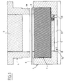
- the stamping device shown in Figs. 1 to 3 comprises a tank 1, the central part of which constitutes a housing for a matrix formed by a cushion 2 made of an elastic material, such as for example an elastomer.
- a frame 3 On the upper face of the elastic cushion 2 is disposed a frame 3 with a closed contour which constitutes a lower peripheral blank holder and which substantially follows the contour of the internal housing of the container 1 so as to be able to penetrate into said housing when the room.
- the stamping device comprises a body 4 carried by an external slide, not shown, and the lower part of which constitutes an upper peripheral blank holder 4a.
- the upper peripheral blank holder 4a has external dimensions slightly smaller than the outline of the internal housing of the container 1 so as to cooperate with the frame 3 and to penetrate into said housing.
- the body 4 has a central well inside which a plunger 5 penetrates, the underside of which constitutes an imprint corresponding to the profile of the finished part to be obtained.
- the device also comprises a first means 10 for absorbing the excess volume of the elastic cushion 2 generated by the application of the plunger 5 by compared to that determined by the surface of the finished part to be obtained during the definitive forming of said part.
- This means 10 is constituted, in this embodiment, by a piston 11 movable vertically constituting the bottom of the retention tank 1, which has for this purpose a central opening la.
- the piston 11 has its upper surface applied against the elastic cushion 2 and cooperates with a regulating member 12 for the movement of said piston.
- This regulating member 12 shown diagrammatically in FIGS. 1 to 3 is constituted for example by a multi-blade brake, or a spring or even a jack.
- the body 4 is lowered by means of the external slide, not shown, from the press, so that the upper blank holder 4a comes into contact with the sheet blank 6 whose peripheral zone is progressively clamped between the lower blank holder 3 and the upper blank holder 4a to avoid its scalloping.
- the upper blank holder 4a compresses the elastic cushion 2 by reaction.
- the swelling of the central part of the sheet blank 6 is limited by the bottom of the plunger 5 in order to avoid uncontrolled deformations.
- the regulating member 12 prevents the displacement of the movable piston 11 under the effect of the pressure exerted in the elastic cushion 2 and, consequently, prevents said elastic cushion from creeping towards the bottom.
- the plunger 5 descends to its low position and controls the final forming of the central part of the sheet blank 6 preformed during the previous operation.
- the regulating member 12 ensures the adjustment of the displacement of the piston 11 and, therefore, makes it possible to absorb the excess volume of the elastic cushion 2 generated by the application of the plunger 5.
- the pressure generated in the cushion is maintained at an adjustment value by automatic compensation for the excess volume of said elastic cushion.
- the device comprises at least a second means 20 for compensating for the excess volume of the elastic cushion 2.
- This compensation means is arranged in a wall of the retention tank 1 and for example in the movable piston 11 as shown in FIGS. 1 to 3.
- the compensation means 20 comprises, on the one hand, at least one sliding member 21 housed in a chamber 22 opening into the retention tank 1 and intended to cooperate with the elastic cushion 2 and, on the other hand, a regulating member 23 for the displacement of the sliding member 21, interposed between said sliding member 21 and the bottom 22a of the chamber 22.
- Chamber 22 can be open on the corresponding wall of the retention tank 1 or closed at the level of said wall by an elastic membrane 24 so as to seal the elastic cushion 2 relative to the device.
- the sliding member 21 is formed by a substantially flat sole having a face 21a flush with the corresponding wall of the retention tank 1 and comprising at its periphery at least one shoe 25 for guiding said sole 21 in the chamber 22.
- These pads are made of a material having good resistance to friction and are fixed in periphery of said sole 21 by means of screws 25a.
- the chamber 22 is extended by a recess 26.
- the regulating member 23 is formed by an elastic element 23a which cooperates with a means 30 for prestressing said elastic element.
- the means 30 for prestressing the elastic element 23a is formed by a rod 31 subject to said elastic element 23a and for example passing through this elastic element 23a and of which a first end 31a is connected to the sole 21, for example by a thread , and a second end 31b of which is provided with an adjustment nut 32 bearing on a plate 33 interposed between the elastic element 23a and the bottom 22a of the chamber 22.
- a washer 34 is placed between the plate 33 and the adjusting nut 32 and this adjusting nut 32 is blocked by a lock nut 35.
- the adjusting nut 32 and the counter nut 35 are disposed in the recess 26.
- the elastic element 23a can be formed for example by a rubber or elastomer block or by a spring or even by a gas spring.
- the regulating member 23 can be formed by a hydraulic system connected to an accumulator for adjusting the pressure or by a pneumatic system.
- This regulating member 23 regulates the movement of the sliding member 21 which has a given stroke whose extreme positions correspond to a minimum determined pressure and to a maximum determined pressure of the material constituting the elastic cushion 2.
- the compensation means thus described makes it possible to obtain an automatic adjustment of the pressure and of the volume of the elastic cushion 2 as the press operates.
- the stamping device may include one or more compensation means placed on a part of the bottom of the retention tank or on one of its side walls.
- the means for compensating for the excess volume of the cushion due to variations in the physical characteristics of the material constituting said cushion can be placed at the bottom of the retention tank or at one of its side walls.
Landscapes
- Engineering & Computer Science (AREA)
- Mechanical Engineering (AREA)
- Shaping Metal By Deep-Drawing, Or The Like (AREA)
- Presses And Accessory Devices Thereof (AREA)
Abstract
Description
La présente invention a pour objet un dispositif d'emboutissage de matériaux en feuille sur une matrice de formage en matériau élastique.The present invention relates to a device for stamping sheet materials on a forming matrix of elastic material.
On connait dans le FR-A-2 641 217 un dispositif d'emboutissage de matériaux en feuille, du type comprenant un coussin en un matériau élastique logé dans un bac de rétention, des moyens de préformage d'un flan de tôle, constitués par un coulisseau extérieur portant un serre-flan supérieur et des moyens de formage définitif dudit flan de tôle constitués par un coulisseau central agissant sur un plongeur.FR-A-2 641 217 discloses a device for stamping sheet materials, of the type comprising a cushion made of an elastic material housed in a retention tank, means for preforming a sheet blank, constituted by an external slide carrying an upper blank holder and means for definitive forming of said sheet blank constituted by a central slide acting on a plunger.
Ce dispositif comporte également des moyens d'absorption du volume excédentaire du coussin élastique par rapport à celui déterminé par la surface de la pièce finie à obtenir.This device also includes means for absorbing the excess volume of the elastic cushion relative to that determined by the surface of the finished part to be obtained.
Ce dispositif permet l'emboutissage d'un matériau en feuille, en particulier d'un matériau à faible allongement qui peut-être notamment une tôle métallique, par exemple d'acier. Ce dispositif n'est pas limité à l'emboutissage de feuilles métalliques, mais peut s'appliquer à des matériaux plastiques et à tout autre matériau composite.This device allows the stamping of a sheet material, in particular of a material with low elongation which may in particular be a metal sheet, for example steel. This device is not limited to the stamping of metal sheets, but can be applied to plastic materials and to any other composite material.
Le coussin en matériau élastique peut être un support composite constitué d'une masse sensiblement parallélépipèdique à base d'un élastomère de silicone, de faible dureté Shore, éventuellement recouvert sur sa face supérieure, et sur la totalité et une partie de ses faces latérales d'une enveloppe relativement mince en un matériau plus résistant et plus dur.The cushion of elastic material can be a composite support consisting of a substantially parallelepipedic mass based on a silicone elastomer, of low Shore hardness, possibly covered on its upper face, and on all and part of its lateral faces d '' a relatively thin envelope made of a more resistant and harder material.
Au cours de l'étape de préformage, le serre-flan appliqué sur la partie périphérique du flan de tôle provoque le fluage de la masse du coussin élastique pour déformer la partie centrale dudit flan de tôle, tout en lui conférant, en fin d'étape de préformage, une surface sensiblement égale à la surface de la pièce à obtenir.During the preforming step, the blank holder applied to the peripheral part of the sheet blank causes the mass of the elastic cushion to creep to deform the central part of said sheet blank, while giving it, at the end of the preforming step, a surface substantially equal to the surface of the part to be obtained.
La descente du plongeur pour la conformation finale du flan de tôle entraîne une élévation de pression dans le coussin et une différence de volume dans ledit coussin, entre l'étape de préformage et l'étape de conformation, qu'il est nécessaire de compenser afin d'éviter une augmentation de pression dans le coussin.The descent of the plunger for the final shaping of the sheet blank causes an increase in pressure in the cushion and a difference in volume in said cushion, between the preforming step and the shaping step, which it is necessary to compensate in order avoid an increase in pressure in the cushion.
En effet, cette augmentation de pression est incompatible avec une tenue mécanique des presses utilisées.This increase in pressure is in fact incompatible with the mechanical strength of the presses used.
Pour cela, le dispositif selon le FR-A-2 641 217 comporte des moyens d'absorption du volume excédentaire du coussin élastique engendré lors de l'application du plongeur.For this, the device according to FR-A-2 641 217 comprises means for absorbing the excess volume of the elastic cushion generated during the application of the plunger.
Ces moyens d'absorption sont déplaçables au cours du formage définitif de la pièce et ce déplacement est réglé par un organe de régulation constitué par exemple par un frein multilames, ou un ressort ou encore un vérin.These absorption means can be moved during the final forming of the part and this movement is regulated by a regulating member constituted for example by a multi-blade brake, or a spring or even a jack.
Ce dispositif connu permet d'absorber des différences de volume importantes, constantes et définies lors du premier cycle de la presse pour une géométrie de pièces à former et à une température donnée.This known device makes it possible to absorb large, constant and defined volume differences during the first press cycle for a geometry of the parts to be formed and at a given temperature.
Mais, ce dispositif présente l'inconvénient de ne pas répondre aux problèmes d'une augmentation de volume progressif, même faible du coussin.However, this device has the drawback of not responding to the problems of a progressive, even small, increase in volume of the cushion.
Cette augmentation peut être due à des variations des caractéristiques physiques du matériau constituant le coussin, comme par exemple un échauffement continu de plusieurs dizaines de degrés généré par la déformation du coussin sous l'action du serre-flan supérieur dont la course peut représenter 20% de la hauteur à vide du coussin pendant la réalisation de pièces à cadence de presse élevée, c'est à dire supérieure à une dizaine de cycles par minute.This increase can be due to variations in the physical characteristics of the material constituting the cushion, such as for example a continuous heating of several tens of degrees generated by the deformation of the cushion under the action of the upper blank holder whose stroke can represent 20%. of the empty height of the cushion during the production of parts with a high press rate, i.e. greater at about ten cycles per minute.
Ces variations des caractéristiques physiques du matériau constituant le coussin entrainent des réglages successifs de la presse ce qui diminue les cadences.These variations in the physical characteristics of the material constituting the cushion cause successive adjustments to the press, which reduces the rates.
Le but de l'invention est la fabrication de pièces avec une presse fonctionnant à une cadence élevée sans nécessiter une modification du réglage de ladite presse pendant les opérations de formage.The object of the invention is the manufacture of parts with a press operating at a high rate without requiring a modification of the setting of said press during the forming operations.
La présente invention a donc pour objet un dispositif d'emboutissage de matériaux en feuille, du type comprenant une matrice formée par un coussin en un matériau élastique, comme par exemple un élastomère, logé dans un bac de rétention, des moyens de préformage d'un flan de tôle, constitués par un coulisseau extérieur portant un serre-flan supérieur, des moyens de formage définitif dudit flan de tôle, constitués par un coulisseau central agissant sur un plongeur et un premier moyen d'absorption du volume excédentaire du coussin par rapport à celui déterminé par la surface de la pièce finie à obtenir au cours du formage définitif de ladite pièce, caractérisé en ce qu'il comprend au moins un second moyen de compensation du volume excédentaire du coussin dû à des variations des caractéristiques physiques du matériau constituant ledit coussin au cours du préformage et du formage définitif de ladite pièce.The present invention therefore relates to a device for stamping sheet materials, of the type comprising a matrix formed by a cushion made of an elastic material, such as for example an elastomer, housed in a retention tank, means for preforming a sheet blank, constituted by an external slide carrying an upper hold-down, means for definitive forming of said sheet blank, constituted by a central slide acting on a plunger and a first means of absorbing the excess volume of the cushion relative to to that determined by the surface of the finished part to be obtained during the definitive forming of said part, characterized in that it comprises at least one second means of compensating for the excess volume of the cushion due to variations in the physical characteristics of the constituent material said cushion during preforming and final forming of said part.
Selon d'autres caractéristiques de l'invention :
- le moyen de compensation est disposé dans une paroi du bac de rétention,
- le moyen de compensation comprend, d'une part, au moins un organe coulissant logé dans une chambre débouchant dans le bac de rétention et destiné à coopérer avec le coussin et, d'autre part, un organe de régulation du déplacement de l'organe coulissant interposé entre ledit organe coulissant et le fond de ladite chambre,
- la chambre est ouverte sur la paroi du bac de rétention,
- la chambre est obturée au niveau de la paroi du bac de rétention par une membrane élastique,
- l'organe coulissant est formé par une semelle sensiblement plane comportant une face affleurant avec ladite paroi du bac de rétention,
- la semelle comporte à sa périphérie au moins un patin de guidage de ladite semelle dans la chambre,
- l'organe de régulation est formé par un élément élastique,
- l'élément élastique coopère avec un moyen de mise en précontrainte,
- le moyen de mise en précontrainte est formé par une tige assujettie à l'élément élastique et dont une première extrémité est reliée à la semelle et dont une seconde extrémité est munie d'un écrou de réglage en appui sur une plaque interposée entre ledit élément élastique et le fond de ladite chambre,
- l'élément élastique est formé par un bloc en caoutchouc ou en élastomère,
- l'élément élastique est formé par un ressort,
- l'organe de régulation est formé par un système hydraulique relié à un accumulateur de réglage de la pression,
- l'organe de régulation est formé par un système pneumatique.
- the compensation means is arranged in a wall of the retention tank,
- the compensation means comprises, on the one hand, at least one sliding member housed in a chamber opening into the retention tank and intended to cooperate with the cushion and, on the other hand, a member for regulating the movement of the member sliding interposed between said sliding member and the bottom of said chamber,
- the chamber is open on the wall of the retention tank,
- the chamber is closed at the wall of the retention tank by an elastic membrane,
- the sliding member is formed by a substantially flat sole having a surface flush with said wall of the retention tank,
- the sole comprises at its periphery at least one shoe for guiding said sole in the chamber,
- the regulating member is formed by an elastic element,
- the elastic element cooperates with a means of prestressing,
- the prestressing means is formed by a rod subject to the elastic element and a first end of which is connected to the sole and a second end of which is provided with an adjustment nut bearing on a plate interposed between said elastic element and the bottom of said chamber,
- the elastic element is formed by a rubber or elastomer block,
- the elastic element is formed by a spring,
- the regulating member is formed by a hydraulic system connected to an accumulator for adjusting the pressure,
- the regulating member is formed by a pneumatic system.
L'invention sera mieux comprise à l'aide de la description qui va suivre, donnée uniquement à titre d'exemple et faite en référence aux dessins annexés, sur lesquels :
- les Figs. 1 à 3 sont des vues schématiques en coupe du dispositif d'emboutissage selon l'invention, au cours des étapes successives de formage d'une pièce,
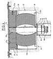
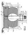
- la Fig. 4 est une vue en coupe et à plus grande échelle des moyens de compensation du volume excédentaire du coussin, en position repos,
- la Fig. 5 est une vue identique à la Fig. 4 montrant le moyen de compensation du volume excédentaire du coussin au cours de l'absorption de ce volume excédentaire.
- Figs. 1 to 3 are schematic views in section of the stamping device according to the invention, during the successive stages of forming a part,
- Fig. 4 is a sectional view on a larger scale of the means for compensating for the excess volume of the cushion, in the rest position,
- Fig. 5 is a view identical to FIG. 4 showing the means of compensating for the excess volume of the cushion during the absorption of this excess volume.
Le dispositif d'emboutissage représenté aux Fig. 1 à 3 comprend un bac 1 dont la partie centrale constitue un logement pour une matrice formée par un coussin 2 en un matériau élastique, comme par exemple un élastomère.The stamping device shown in Figs. 1 to 3 comprises a
Sur la face supérieure du coussin élastique 2 est disposé un cadre 3 à contour fermé qui constitue un serre-flan périphérique inférieur et qui épouse sensiblement le contour du logement interne du bac 1 de façon à pouvoir pénétrer dans ledit logement au moment du formage de la pièce.On the upper face of the
Au-dessus du bac 1, le dispositif d'emboutissage comporte un corps 4 porté par un coulisseau extérieur, non représenté, et dont la partie inférieure constitue un serre-flan périphérique supérieur 4a.Above
Le serre-flan périphérique supérieur 4a a des dimensions extérieures légèrement inférieures au contour du logement interne du bac 1 de façon à coopérer avec le cadre 3 et à pénétrer dans ledit logement.The upper peripheral
Le corps 4 comporte un puits central à l'intérieur duquel pénètre un plongeur 5 dont la face inférieure constitue une empreinte correspondant au profil de la pièce finie à obtenir.The
Le dispositif comporte également un premier moyen 10 d'absorption du volume excédentaire du coussin élastique 2 engendré par l'application du plongeur 5 par rapport à celui déterminé par la surface de la pièce finie à obtenir au cours du formage définitif de ladite pièce.The device also comprises a
Ce moyen 10 est constitué, dans cet exemple de réalisation, par un piston 11 mobile verticalement constituant le fond du bac de rétention 1, qui comporte à cet effet une ouverture centrale la. Le piston 11 a sa surface supérieure appliquée contre le coussin élastique 2 et coopère avec un organe de régulation 12 du déplacement dudit piston.This means 10 is constituted, in this embodiment, by a
Cet organe de régulation 12 schématisé sur les Figs. 1 à 3, est constitué par exemple par un frein multilames, ou un ressort ou encore un vérin.This regulating
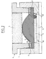
Au cours de l'étape de préformage illustrée à la Fig. 2, on fait descendre par l'intermédiaire du coulisseau extérieur, non représenté, de la presse, le corps 4 de telle manière que le serre-flan supérieur 4a entre en contact avec le flan de tôle 6 dont la zone périphérique est progressivement serrée entre le serre-flan inférieur 3 et le serre-flan supérieur 4a pour éviter son festonnage.During the preforming step illustrated in FIG. 2, the
Au cours de la descente, le serre-flan supérieur 4a comprime par réaction le coussin élastique 2.During the descent, the upper
Ce dernier, sous l'effet de cette action périphérique, agit par fluage sur la zone centrale du flan de tôle 6 et provoque sa déformation.The latter, under the effect of this peripheral action, acts by creep on the central zone of the sheet blank 6 and causes its deformation.
Le gonflement de la partie centrale du flan de tôle 6 est limité par le fond du plongeur 5 afin d'éviter des déformations incontrôlées.The swelling of the central part of the sheet blank 6 is limited by the bottom of the
Dès le début de la descente du serre-flan supérieur 4a, l'organe de régulation 12 empêche le déplacement du piston mobile 11 sous l'effet de la pression excercée dans le coussin élastique 2 et, par conséquent, empêche ledit coussin élastique de fluer vers le bas.From the start of the descent of the upper
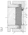
Pendant l'étape de conformation finale du flan de tôle 6 représentée à la Fig. 3, le plongeur 5 descend à sa position basse et contrôle le formage final de la partie centrale du flan de tôle 6 préformé au cours de l'opération précédente.During the final shaping step of the sheet blank 6 shown in FIG. 3, the
Les contraintes dues à l'appui du plongeur 5 sur le sommet du flan de tôle 6 provoquent le déplacement de ce flan dans tout le volume disponible et permettent ainsi la réalisation finale de la pièce avec un minimum de variation d'épaisseur.The stresses due to the support of the
L'organe de régulation 12 assure le réglage du déplacement du piston 11 et, de ce fait, permet d'absorber le volume excédentaire du coussin élastique 2 engendré par l'application du plongeur 5.The regulating
Si un tel dispositif est acceptable pour absorber des différences de volume importantes, constantes et définies, dès le premier cycle de presse, calculées en fonction de la pièce à former, il n'est pas adapté à des augmentations de volume progressives, même faibles du coussin élastique 2 dues à des variations des caractéristiques physiques du matériau constituant ledit coussin, comme par exemple un échauffement continu de plusieurs dizaines de degrés à cause d'un travail de la presse à cadence élevée généralement supérieure ou égale à dix cycles par minute et un taux de compression en partie latérale pouvant atteindre 20%.If such a device is acceptable for absorbing large, constant and defined volume differences, from the first press cycle, calculated as a function of the part to be formed, it is not suitable for gradual, even small, volume increases in the
Cette faible augmentation de volume entraine une forte augmentation de la pression dans le coussin élastique 2 et un effort plus important sur le coulisseau de la presse.This small increase in volume results in a large increase in the pressure in the
Sur les presses de transfert de carrosserie, plusieurs outils sont juxtaposés sur le même coulisseau et un réglage approprié du seul outil d'emboutissage sur le coussin élastique en cours de fabrication des pièces en grande série n'est pas envisageable.On the body transfer presses, several tools are juxtaposed on the same slide and an appropriate adjustment of the only stamping tool on the elastic cushion during the manufacturing of the parts in large series is not possible.
Pour palier ces augmentations de volume dues à des variations de caractéristiques physiques des éléments du dispositif et en particulier du coussin élastique, on maintient, à un valeur de réglage, la pression générée dans le coussin par une compensation automatique du volume excédentaire dudit coussin élastique.To compensate for these volume increases due to variations in the physical characteristics of the elements of the device and in particular of the elastic cushion, the pressure generated in the cushion is maintained at an adjustment value by automatic compensation for the excess volume of said elastic cushion.
A cet effet, le dispositif comprend au moins un second moyen 20 de compensation du volume excédentaire du coussin élastique 2.To this end, the device comprises at least a second means 20 for compensating for the excess volume of the
Ce moyen de compensation est disposé dans une paroi de bac de rétention 1 et par exemple dans le piston mobile 11 comme représenté sur les Figs. 1 à 3.This compensation means is arranged in a wall of the
Comme représenté plus en détails sur les Figs. 4 et 5, le moyen de compensation 20 comprend, d'une part, au moins un organe coulissant 21 logé dans une chambre 22 débouchant dans le bac de rétention 1 et destiné à coopérer avec le coussin élastique 2 et, d'autre part, un organe de régulation 23 du déplacement de l'organe coulissant 21, interposé entre ledit organe coulissant 21 et le fond 22a de la chambre 22.As shown in more detail in Figs. 4 and 5, the compensation means 20 comprises, on the one hand, at least one sliding
La chambre 22 peut être ouverte sur la paroi correspondante du bac de rétention 1 ou obturée au niveau de ladite paroi par une membrane élastique 24 de manière à assurer l'étanchéité du coussin élastique 2 par rapport au dispositif.
L'organe coulissant 21 est formé par une semelle sensiblement plane comportant une face 21a affleurant avec la paroi correspondante du bac de rétention 1 et comportant à sa périphérie au moins un patin 25 de guidage de ladite semelle 21 dans la chambre 22.The sliding
Ces patins sont réalisés en un matériau ayant une bonne résistance aux frottements et sont fixés en périphérie de ladite semelle 21 au moyen de vis 25a.These pads are made of a material having good resistance to friction and are fixed in periphery of said sole 21 by means of
La chambre 22 se prolonge par un évidement 26.The
L'organe de régulation 23 est formé par un élément élastique 23a qui coopère avec un moyen 30 de mise en précontrainte dudit élément élastique.The regulating
Le moyen 30 de mise en précontrainte de l'élément élastique 23a est formé par une tige 31 assujettie audit élément élastique 23a et par exemple traversant cet élément élastique 23a et dont une première extrémité 31a est reliée à la semelle 21, par exemple par un filetage, et dont une seconde extrémité 31b est munie d'un écrou de réglage 32 en appui sur une plaque 33 interposée entre l'élément élastique 23a et le fond 22a de la chambre 22.The means 30 for prestressing the
Une rondelle 34 est placée entre la plaque 33 et l'écrou de réglage 32 et cet écrou de réglage 32 est bloqué par un contre écrou 35.A
L'écrou de réglage 32 et le contre écrou 35 sont disposés dans l'évidement 26.The adjusting
L'élément élastique 23a peut être formé par exemple par un bloc en caoutchouc ou en élastomère ou par un ressort ou encore par un ressort à gaz.The
L'organe de régulation 23 peut être formé par un système hydraulique relié à un accumulateur de réglage de la pression ou par un système pneumatique.The regulating
En cas d'une augmentation progressive, même faible du volume du coussin élastique 2 due à des variations des caractéristiques physiques du matériau constituant ledit coussin, comme par exemple un échauffement, l'organe coulissant 21 se déplace dans la chambre 22 ce qui provoque une compression de l'organe de régulation 23, comme représenté sur la Fig.5, permettant ainsi d'absorber le volume excédentaire de ce coussin élastique 2.In the event of a progressive increase, even a small one, in the volume of the
Cet organe de régulation 23 règle le déplacement de l'organe coulissant 21 qui possède une course donnée dont les positions extrêmes correspondent à une pression déterminée minimum et à une pression déterminée maximum du matériau constituant le coussin élastique 2.This regulating
Le moyen de compensation ainsi décrit permet d'obtenir un réglage automatique de la pression et du volume du coussin élastique 2 au fur et à mesure du fonctionnement de la presse.The compensation means thus described makes it possible to obtain an automatic adjustment of the pressure and of the volume of the
Le dispositif d'emboutissage peut comprendre un ou plusieurs moyens de compensation placés sur une partie du fond du bac de rétention ou sur une de ses parois latérales.The stamping device may include one or more compensation means placed on a part of the bottom of the retention tank or on one of its side walls.
Dans les dispositifs de mise en forme de flans de tôle sur presse et outil à simple effet dans lesquels il n'est pas utilisé de moyens 10 d'absorption du volume excédentaire du coussin élastique, le moyen de compensation du volume excédentaire du coussin dû à des variations des caractéristiques physiques du matériau constituant ledit coussin peut être placé au niveau du fond du bac de rétention ou au niveau de l'une de ses parois latérales.In devices for shaping sheet blanks on a press and a single-acting tool in which no means 10 for absorbing the excess volume of the elastic cushion are used, the means for compensating for the excess volume of the cushion due to variations in the physical characteristics of the material constituting said cushion can be placed at the bottom of the retention tank or at one of its side walls.
Claims (14)
Applications Claiming Priority (2)
| Application Number | Priority Date | Filing Date | Title |
|---|---|---|---|
| FR9206502 | 1992-05-27 | ||
| FR9206502A FR2691653B1 (en) | 1992-05-27 | 1992-05-27 | Device for stamping sheet materials on a forming matrix of elastic material. |
Publications (2)
| Publication Number | Publication Date |
|---|---|
| EP0572301A1 true EP0572301A1 (en) | 1993-12-01 |
| EP0572301B1 EP0572301B1 (en) | 1996-07-24 |
Family
ID=9430242
Family Applications (1)
| Application Number | Title | Priority Date | Filing Date |
|---|---|---|---|
| EP93401288A Expired - Lifetime EP0572301B1 (en) | 1992-05-27 | 1993-05-18 | Deep-drawing device for sheet material in a die made of resiliently deformable material |
Country Status (7)
| Country | Link |
|---|---|
| US (1) | US5361617A (en) |
| EP (1) | EP0572301B1 (en) |
| JP (1) | JPH07275962A (en) |
| CA (1) | CA2096461A1 (en) |
| DE (1) | DE69303773T2 (en) |
| ES (1) | ES2090906T3 (en) |
| FR (1) | FR2691653B1 (en) |
Cited By (3)
| Publication number | Priority date | Publication date | Assignee | Title |
|---|---|---|---|---|
| EP0739663A3 (en) * | 1995-04-24 | 1997-08-27 | Trumpf Gmbh & Co | Machine for forming parts |
| EP0888833A1 (en) * | 1997-07-04 | 1999-01-07 | Humard Automation SA | Method and Press for stamping differently and/or sequentially in at least two different directions |
| CN103331935A (en) * | 2013-06-23 | 2013-10-02 | 苏州腾行精密模具有限公司 | Symmetric hole site stamping die |
Families Citing this family (10)
| Publication number | Priority date | Publication date | Assignee | Title |
|---|---|---|---|---|
| JP2595448B2 (en) * | 1993-07-14 | 1997-04-02 | 日本製紙株式会社 | Pulp mold manufacturing method |
| FR2715335B1 (en) * | 1994-01-21 | 1996-04-05 | Lorraine Laminage | Device for stamping a sheet blank. |
| KR100284270B1 (en) * | 1998-09-23 | 2001-03-02 | 김태선 | Pressure forming apparatus and method for forming solid pattern of metal sheet using mold and synthetic rubber sheet |
| DE10016804B4 (en) * | 2000-04-05 | 2004-11-11 | Thyssenkrupp Stahl Ag | Method and device for producing components from a deep-drawn board |
| US6233989B1 (en) | 2000-10-13 | 2001-05-22 | Changing Paradigms, Llc | Method and apparatus for stamping a metal sheet with an apertured design having rolled edges |
| WO2012151416A1 (en) * | 2011-05-03 | 2012-11-08 | Kairis Paul R | Cover for striking device for percussion instrument |
| DE202012003953U1 (en) | 2012-04-20 | 2012-07-13 | Michael Konrath | stop Stock |
| CN105013918A (en) * | 2015-07-02 | 2015-11-04 | 奇瑞汽车股份有限公司 | Complicated surface plate drawing mold and control method thereof |
| CN111842637B (en) * | 2020-07-03 | 2023-07-14 | 北京航星机器制造有限公司 | Composite forming die and forming method for titanium alloy deep cavity component |
| CN116372022A (en) * | 2023-02-20 | 2023-07-04 | 江铃汽车股份有限公司 | A drawing die and its control method |
Citations (3)
| Publication number | Priority date | Publication date | Assignee | Title |
|---|---|---|---|---|
| FR2462262A1 (en) * | 1979-07-31 | 1981-02-13 | Bretagne Atel Chantiers | Stamping press for sheet metal workpiece - has tool and elastomer block working with membrane inflated by fluid pressure |
| EP0165133A1 (en) * | 1984-05-17 | 1985-12-18 | Sollac | Method and apparatus for stamping sheet metal |
| FR2641217A1 (en) * | 1988-12-30 | 1990-07-06 | Isoform | METHOD AND DEVICE FOR SCRAPPING SHEET MATERIALS ON AN ELASTIC FORMING MATRIX |
Family Cites Families (2)
| Publication number | Priority date | Publication date | Assignee | Title |
|---|---|---|---|---|
| FR2590814B1 (en) * | 1985-12-04 | 1988-02-26 | Usinor | METHOD AND DEVICE FOR SCRAPPING LOW ELONGATION SHEETS |
| SU1683841A1 (en) * | 1989-01-03 | 1991-10-15 | Научно-исследовательский институт средств автоматизации | Apparatus for forming by elastic medium |
-
1992
- 1992-05-27 FR FR9206502A patent/FR2691653B1/en not_active Expired - Fee Related
-
1993
- 1993-05-18 CA CA002096461A patent/CA2096461A1/en not_active Abandoned
- 1993-05-18 ES ES93401288T patent/ES2090906T3/en not_active Expired - Lifetime
- 1993-05-18 DE DE69303773T patent/DE69303773T2/en not_active Expired - Fee Related
- 1993-05-18 EP EP93401288A patent/EP0572301B1/en not_active Expired - Lifetime
- 1993-05-25 US US08/066,660 patent/US5361617A/en not_active Expired - Fee Related
- 1993-05-27 JP JP5126204A patent/JPH07275962A/en not_active Withdrawn
Patent Citations (3)
| Publication number | Priority date | Publication date | Assignee | Title |
|---|---|---|---|---|
| FR2462262A1 (en) * | 1979-07-31 | 1981-02-13 | Bretagne Atel Chantiers | Stamping press for sheet metal workpiece - has tool and elastomer block working with membrane inflated by fluid pressure |
| EP0165133A1 (en) * | 1984-05-17 | 1985-12-18 | Sollac | Method and apparatus for stamping sheet metal |
| FR2641217A1 (en) * | 1988-12-30 | 1990-07-06 | Isoform | METHOD AND DEVICE FOR SCRAPPING SHEET MATERIALS ON AN ELASTIC FORMING MATRIX |
Cited By (3)
| Publication number | Priority date | Publication date | Assignee | Title |
|---|---|---|---|---|
| EP0739663A3 (en) * | 1995-04-24 | 1997-08-27 | Trumpf Gmbh & Co | Machine for forming parts |
| EP0888833A1 (en) * | 1997-07-04 | 1999-01-07 | Humard Automation SA | Method and Press for stamping differently and/or sequentially in at least two different directions |
| CN103331935A (en) * | 2013-06-23 | 2013-10-02 | 苏州腾行精密模具有限公司 | Symmetric hole site stamping die |
Also Published As
| Publication number | Publication date |
|---|---|
| DE69303773T2 (en) | 1997-03-20 |
| FR2691653A1 (en) | 1993-12-03 |
| FR2691653B1 (en) | 1994-08-26 |
| JPH07275962A (en) | 1995-10-24 |
| CA2096461A1 (en) | 1993-11-28 |
| EP0572301B1 (en) | 1996-07-24 |
| ES2090906T3 (en) | 1996-10-16 |
| DE69303773D1 (en) | 1996-08-29 |
| US5361617A (en) | 1994-11-08 |
Similar Documents
| Publication | Publication Date | Title |
|---|---|---|
| EP0572301B1 (en) | Deep-drawing device for sheet material in a die made of resiliently deformable material | |
| EP0376809B1 (en) | Method and device for deep-drawing sheet materials on an elsatic formation lower die | |
| EP0664168B1 (en) | Device for deep-drawing of a sheet metal blank | |
| EP0376808B1 (en) | Method and device for deep-drawing sheet materials with a stamp deformable underneath a plunger | |
| EP0435722A1 (en) | Method and device for forming a sheet metal blank in particular for producing a mask for a cathode ray tube | |
| EP0380894B1 (en) | Device for deep-drawing sheet materials | |
| EP0541427A1 (en) | Device for press-forming sheet materials especially metal blanks | |
| KR102018916B1 (en) | Method for manufacturing cylinder device | |
| FR2564035A1 (en) | PRESSING AND PUNCHING PRESS AND DIE FOR CARRYING OUT SAID METHOD | |
| GB1589666A (en) | Press for producing plates and similar articles | |
| FR2571460A1 (en) | CONTINUOUSLY ADJUSTABLE LENGTH ADJUSTING DEVICE | |
| EP0491602B1 (en) | Device for press-forming sheet materials and especially metal blanks | |
| AU2007345439A1 (en) | Method and device for deep drawing blanks made of sheet metal into flangeless molded blanks | |
| US4827839A (en) | Hydraulic overload protector for mechanical press | |
| JP5086651B2 (en) | Press forming equipment | |
| FR2514691A1 (en) | Stamping cushion for presses | |
| FR2733177A1 (en) | Stamping process for non-symmetrical workpieces which cannot be moulded | |
| KR100372314B1 (en) | Column unit for chair | |
| US3605193A (en) | Apparatus for forming hollow articles made of thermoplastics material | |
| FR2744380A1 (en) | Fabrication of metal components by hydraulic presses | |
| EP0636436B1 (en) | Process of and apparatus for forming a metallic container cover and metallic cover obtained by that process | |
| JPH01202322A (en) | Fluid pressure fabricating device | |
| EP0778796A1 (en) | Constant volume hydraulic stamping method | |
| JPH078401B2 (en) | Molding device for cup-shaped products with internal teeth | |
| JPH0557391A (en) | Forge-forming apparatus |
Legal Events
| Date | Code | Title | Description |
|---|---|---|---|
| PUAI | Public reference made under article 153(3) epc to a published international application that has entered the european phase |
Free format text: ORIGINAL CODE: 0009012 |
|
| 17P | Request for examination filed |
Effective date: 19930910 |
|
| AK | Designated contracting states |
Kind code of ref document: A1 Designated state(s): DE ES FR GB IT |
|
| GRAG | Despatch of communication of intention to grant |
Free format text: ORIGINAL CODE: EPIDOS AGRA |
|
| GRAH | Despatch of communication of intention to grant a patent |
Free format text: ORIGINAL CODE: EPIDOS IGRA |
|
| 17Q | First examination report despatched |
Effective date: 19951221 |
|
| GRAH | Despatch of communication of intention to grant a patent |
Free format text: ORIGINAL CODE: EPIDOS IGRA |
|
| GRAA | (expected) grant |
Free format text: ORIGINAL CODE: 0009210 |
|
| AK | Designated contracting states |
Kind code of ref document: B1 Designated state(s): DE ES FR GB IT |
|
| REF | Corresponds to: |
Ref document number: 69303773 Country of ref document: DE Date of ref document: 19960829 |
|
| GBT | Gb: translation of ep patent filed (gb section 77(6)(a)/1977) |
Effective date: 19960830 |
|
| ITF | It: translation for a ep patent filed | ||
| REG | Reference to a national code |
Ref country code: ES Ref legal event code: FG2A Ref document number: 2090906 Country of ref document: ES Kind code of ref document: T3 |
|
| REG | Reference to a national code |
Ref country code: ES Ref legal event code: FG2A Ref document number: 2090906 Country of ref document: ES Kind code of ref document: T3 |
|
| PLBE | No opposition filed within time limit |
Free format text: ORIGINAL CODE: 0009261 |
|
| STAA | Information on the status of an ep patent application or granted ep patent |
Free format text: STATUS: NO OPPOSITION FILED WITHIN TIME LIMIT |
|
| 26N | No opposition filed | ||
| REG | Reference to a national code |
Ref country code: GB Ref legal event code: IF02 |
|
| PGFP | Annual fee paid to national office [announced via postgrant information from national office to epo] |
Ref country code: GB Payment date: 20020510 Year of fee payment: 10 Ref country code: DE Payment date: 20020510 Year of fee payment: 10 |
|
| PGFP | Annual fee paid to national office [announced via postgrant information from national office to epo] |
Ref country code: ES Payment date: 20020514 Year of fee payment: 10 |
|
| PGFP | Annual fee paid to national office [announced via postgrant information from national office to epo] |
Ref country code: FR Payment date: 20020515 Year of fee payment: 10 |
|
| PG25 | Lapsed in a contracting state [announced via postgrant information from national office to epo] |
Ref country code: GB Free format text: LAPSE BECAUSE OF NON-PAYMENT OF DUE FEES Effective date: 20030518 |
|
| PG25 | Lapsed in a contracting state [announced via postgrant information from national office to epo] |
Ref country code: ES Free format text: LAPSE BECAUSE OF NON-PAYMENT OF DUE FEES Effective date: 20030519 |
|
| PG25 | Lapsed in a contracting state [announced via postgrant information from national office to epo] |
Ref country code: DE Free format text: LAPSE BECAUSE OF NON-PAYMENT OF DUE FEES Effective date: 20031202 |
|
| GBPC | Gb: european patent ceased through non-payment of renewal fee |
Effective date: 20030518 |
|
| PG25 | Lapsed in a contracting state [announced via postgrant information from national office to epo] |
Ref country code: FR Free format text: LAPSE BECAUSE OF NON-PAYMENT OF DUE FEES Effective date: 20040130 |
|
| REG | Reference to a national code |
Ref country code: FR Ref legal event code: ST |
|
| REG | Reference to a national code |
Ref country code: ES Ref legal event code: FD2A Effective date: 20030519 |
|
| PG25 | Lapsed in a contracting state [announced via postgrant information from national office to epo] |
Ref country code: IT Free format text: LAPSE BECAUSE OF NON-PAYMENT OF DUE FEES Effective date: 20050518 |