EP0571378B1 - Gepäckträger für ein/an einem zweiradfahrzeug - Google Patents
Gepäckträger für ein/an einem zweiradfahrzeug Download PDFInfo
- Publication number
- EP0571378B1 EP0571378B1 EP91904118A EP91904118A EP0571378B1 EP 0571378 B1 EP0571378 B1 EP 0571378B1 EP 91904118 A EP91904118 A EP 91904118A EP 91904118 A EP91904118 A EP 91904118A EP 0571378 B1 EP0571378 B1 EP 0571378B1
- Authority
- EP
- European Patent Office
- Prior art keywords
- container
- luggage carrier
- lid
- seat
- carrier according
- Prior art date
- Legal status (The legal status is an assumption and is not a legal conclusion. Google has not performed a legal analysis and makes no representation as to the accuracy of the status listed.)
- Expired - Lifetime
Links
- 238000009423 ventilation Methods 0.000 claims description 5
- 239000002184 metal Substances 0.000 claims description 4
- 239000004033 plastic Substances 0.000 claims description 4
- 230000006378 damage Effects 0.000 claims description 3
- 208000027418 Wounds and injury Diseases 0.000 claims description 2
- 208000014674 injury Diseases 0.000 claims description 2
- 238000007789 sealing Methods 0.000 claims description 2
- 230000001012 protector Effects 0.000 claims 2
- 230000000717 retained effect Effects 0.000 claims 2
- 230000015572 biosynthetic process Effects 0.000 description 8
- 238000003780 insertion Methods 0.000 description 5
- 230000037431 insertion Effects 0.000 description 5
- 238000013016 damping Methods 0.000 description 2
- 241001295925 Gegenes Species 0.000 description 1
- CDBYLPFSWZWCQE-UHFFFAOYSA-L Sodium Carbonate Chemical compound [Na+].[Na+].[O-]C([O-])=O CDBYLPFSWZWCQE-UHFFFAOYSA-L 0.000 description 1
- 235000013405 beer Nutrition 0.000 description 1
- 238000005452 bending Methods 0.000 description 1
- 230000009286 beneficial effect Effects 0.000 description 1
- 239000000969 carrier Substances 0.000 description 1
- 238000006243 chemical reaction Methods 0.000 description 1
- 230000002349 favourable effect Effects 0.000 description 1
- 238000007373 indentation Methods 0.000 description 1
- 230000007704 transition Effects 0.000 description 1
Images


Classifications
-
- B—PERFORMING OPERATIONS; TRANSPORTING
- B62—LAND VEHICLES FOR TRAVELLING OTHERWISE THAN ON RAILS
- B62J—CYCLE SADDLES OR SEATS; AUXILIARY DEVICES OR ACCESSORIES SPECIALLY ADAPTED TO CYCLES AND NOT OTHERWISE PROVIDED FOR, e.g. ARTICLE CARRIERS OR CYCLE PROTECTORS
- B62J1/00—Saddles or other seats for cycles; Arrangement thereof; Component parts
- B62J1/14—Separate pillions
- B62J1/16—Separate pillions for children
-
- B—PERFORMING OPERATIONS; TRANSPORTING
- B62—LAND VEHICLES FOR TRAVELLING OTHERWISE THAN ON RAILS
- B62J—CYCLE SADDLES OR SEATS; AUXILIARY DEVICES OR ACCESSORIES SPECIALLY ADAPTED TO CYCLES AND NOT OTHERWISE PROVIDED FOR, e.g. ARTICLE CARRIERS OR CYCLE PROTECTORS
- B62J9/00—Containers specially adapted for cycles, e.g. panniers or saddle bags
- B62J9/20—Containers specially adapted for cycles, e.g. panniers or saddle bags attached to the cycle as accessories
- B62J9/23—Containers specially adapted for cycles, e.g. panniers or saddle bags attached to the cycle as accessories above or alongside the rear wheel
Definitions
- the invention relates to a luggage rack for a two-wheeled vehicle, which has a container with two chambers open at the top and a cover that closes these chambers and covers the top of the container, with a space designed as a wheel housing for gripping over a wheel of the two-wheeled vehicle between the two chambers is present when the luggage rack is attached to the frame of the two-wheeled vehicle.
- Such a luggage rack is known from FR-A-2 574 040, which is designed as a carrying bag for a baby (child) and for holding goods in the chambers.
- the lid In the folded-up position, the lid forms a backrest and armrests for the child in use and covers the top of the carrying bag in the folded-down position.
- a suitcase for a bicycle which also has two chambers for receiving goods and a case lid, which is in a closed position on top of the case for the transport of goods and in one on the Suitcase back definable position when taking a child sitting with a cushion on the chambers is removable and fixable.
- GB-A-2 091 176 discloses a combined luggage and child carrier which also has a container with two compartments for receiving goods and for adjusting a child's feet.
- a cover that closes the chambers and covers the container is designed as a removable seat part, which is suitable for holding children in the container twisted position is used and results in a seat and backrest.
- the luggage carriers known from the prior art show the disadvantage of an unfavorable handling of their cover for the conversion into a child seat as well as an insufficient position fixation and unsafe child reception.
- the object of the invention is to improve a luggage carrier constructed according to the type mentioned above in such a way that the luggage carrier can be converted into a safe child seat in a simple manner and the cover is simply changed relative to the container and is securely fixed in position in the sitting position.
- the luggage rack according to the invention on the one hand offers a high storage and storage capacity for objects of the most varied types both in its cavity and on its cover and on the other hand can be easily converted into a child's seat by simple means, the cover as a seat shell being secured relative to the container by support - and support points, a security fitting and tension belts are locked.
- the load of the seat is introduced and distributed over a large area into the container via the support and support points as well as the fitting and the straps.
- the conveniently arranged stand is easily and conveniently pivoted into the respective position on the container, shows a simple fixation on the container in the non-use position and an extremely favorable support position in the vehicle elevation and here the load forces are also distributed over a large area and distributed into the container side walls.
- the straps are equipped with simple, easy-to-use and extremely secure belt locks (belt straps and fitting parts that accommodate them) and the luggage rack is equipped with a safe and functional lid lock and removable weather protection.
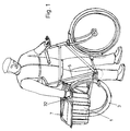
- the luggage rack for / on a two-wheeled vehicle has a container (1) with two chambers (4) lying on both sides of a wheel arch (2) and extending on both sides of a wheel (3) and is fastened on the one hand to the vehicle frame (5) and on the other hand in the wheel hub area supported; the container opening (6) at the top is closed by a cover (7).
- This cover (7) is designed as a seat shell and is pivotally mounted with a shell edge (8) in a horizontal pivot axis (9) of a guide fitting (10) from the closed position (FIG. 3) into a raised position (FIG. 4) and with it Guide fitting (10) can be pivoted about a second horizontal pivot axis (11) in the raised position via the container opening (6) onto the wheel arch (2) as a child seat and in this position is supported in a fixed position by the guide fitting (10) and wheel arch (2).
- the guide fitting (10) is opposed in the closed position of the cover (7) by a locking rod (12) for opening and closing the cover (7) and in the raised position of the cover (7) by locking means (13/14) the container (1) locked in its two pivoted positions (Fig. 4 to 6).
- the guide fitting (10) has two lateral angle levers with lever legs (10a, 10b) which are at an obtuse angle to one another and of different lengths, of which the shorter lever leg (10a) receives the pivot axis (9) for the cover (7) in its free end and with the free one End of the longer lever arm (10b) is pivotally mounted in the second pivot axis (11) in the upper side edge of the container (1).
- the displaceable locking rod (12) secured in at least one locking lever (12a) (Fig. 6) engages in both displaced positions and in the second Hold the position on the container (1) with molded catches (13) (Fig. 5).
- 2, 4, 6 and 7 security fitting (20) is a U-shaped, about a horizontal axis (21) on the wheel arch (2) height-pivotable rocker arm (22) with at the free end of the lever molded locking lug (22a) acting on the seat edge (8).
- Each fitting part (60) and the cooperating, releasably insertable strap tab (18) form counterparts of a buckle.
- the belt buckle (23) of the fitting safety belt (24) is designed as a turnbuckle and has a tensioning lever (23b) which can be pivoted about an axis (23a) and into which the end of the belt is looped several times through slots (23c).
- the tensioning lever (23b) with belt (24) is brought into the tensioning position about its axis (23a) beyond a dead center position (FIG. 7).
- a sealing profile (28) is arranged around the edge of the cover (7) except for the seat edge (8) and a cushioning mat (29) is removably inserted in the seat shell (7), which is located between the wheel arch (2) and the securing fitting (20) and securing lug (22a) is fixed while avoiding injury points and to form a smooth transition to the security fitting (20). (Fig.6).
- the container (1) has on its side adjacent to the frame attachment a raised front cross bridge (31), the handles (32), ventilation slots (33) and a fastening point (30) on the frame (5) and for a lock (34) and has on its opposite side a lower rear transverse bridge (35) on which in the closed position the cover (7) is supported with its seat edge (8) showing the axis (9) (FIGS. 3 to 6) .
- An attachment bracket (37) for attaching the container (1) to the dropout of the vehicle frame (5) is arranged in an indentation (36) in the base (4a) of both chambers (4), which, with its horizontal, under the bulge (36 ) lying leg (37a) by means of an elongated hole (38) and engaging fastening screw (42) in the hub-axis direction to compensate for different axis lengths is continuously adjustable and in its vertically downward leg (37b) several push-through holes (39) for a fastening screw on Dropout has (Fig. 3 and 8).
- the holes (39) in the vertical leg (37b) form a hole pattern for attachment to different dropouts.
- the tensioning lever (23b) of the fitting safety belt (24) can be mounted on this counterplate (41) at the same time.
- a U-bracket-shaped stand (45) is hingedly mounted about an axis (44) running coaxially to the wheel axis, which post (45a ), which holds the stand (45) at a distance in front of the wheel axle in the swiveled stand position (wheel elevation) and is supported in the formation (43) and in the swung up position Raises the non-use position behind a latching hook (46) with a foot actuation attachment (47) which is resiliently mounted on the container (1) (FIGS. 2, 3 and 8).
- the latching hook (46) with foot actuation attachment (47) is formed from a one-piece plastic part, which is latched into a recess (49) of a recess (50) of the container (1) with a latching lug (48) and around this latching connection (48,49 ) is pivotable and resilient in a certain range.
- the latching hook (46) is lined with a damping layer (52), such as a rubber part, at least in its latching groove (51) receiving the stand (45).
- a ramp (53) formed on the latching hook (46) enables the stand (45) to be easily latched into the latching groove (51), in which the swiveling stand (45) presses the latching hook (46) back over the bevel (53), which then due to its swiveling and resilient design, it swings back automatically via the stand (45) pivoted into the locking groove (51) (FIG. 9).
- a slide piece (72) is inserted in the stator bearing eye (45b), in which the screw (44) engages and around which the stator (45) covers a large area and the forces that occur, rotatably and laterally supported is.
- the stand (45) is designed to be infinitely height-adjustable, in which its lower U-bracket (45 c) is opposite the stand parts (45, 45 a) on the swivel axis side. is displaceable and lockable by means of screws, socket bolts, clamping parts or the like (FIG. 2).
- the lock (34) which can be seen in Fig. 3, 4 and 6, is formed by a security lock with an insertion channel (34 a) for an end locking pin (55a) of a safety rope (55), the locking pin (55a) simultaneously a lock flap (56) of the cover (7) passes through.
- This lock (34) is pivotally mounted in a U-shaped bearing bracket (57) attached to the front cross bridge (31).
- the lock flap (56) is inserted over the lock (34) and the locking pin (55a) then engages laterally through the lock flap (56) and laterally into the lock (34) and then the Locking pin (55a) is fixed by locking the lock (34).
- the safety rope (55) has an arbitrarily large length and can be looped around the luggage rack and around and through the bike, around a fixed point (tree, sign post or the like) for securing.
- the end of the rope facing away from the securing pin (55a) is passed under the wheel arch (2) and fastened underneath it so that it is not accessible from the outside.
- the belt buckle (18, 60) according to FIGS. 11 to 14 consists of a belt tab (18) with a resilient holding and locking part (61) for the belt end (26a) and a fitting part (60) with an insertion opening (62) for the belt tab ( 18) and a recess (63) which forms a locking edge (63a) for the holding and locking part (61) and an actuating opening for releasing the holding and locking part (61).
- the belt tab (18) is made in one piece from metal or plastic and has in a frame part (64) the spring-connected holding and locking part (61), which has a plurality of through slots (65) for the belt end (26 a) and a locking edge ( 66) and protrudes obliquely from the plane of the frame part (64) and can be moved into the frame part (64) to release the belt flap (18) from the fitting part (60).
- the fitting part (60) is formed by a flat U-shaped profile made of sheet metal or plastic, in the U-web (60a) of which the actuation opening (63) and in a U-leg (60b) the insertion opening (62) are cut out in a slot shape ; the profile web between the actuating opening (63) and the insertion opening (62) results in the latching edge (63a) for the latching and holding part (61).
- the fitting part (60) as shown in FIG. 4, extends into the side walls of the seat shell (7), resulting in stiffening of the cover (7) and securing it against possible bending up, damage and thus theft in the side area.
- the belt flap (18) with the belt end (26a) looped several times through the slots (65) is inserted from below or above into the slot-shaped insertion opening (62) of the fitting part (60) and the protruding holding and latching part (61) around it resilient connecting web (61a) to the frame part (64) pressed into the frame part (64). If the belt flap (18) is inserted, the cold and locking part (61) automatically springs into the opening (63) of the fitting part (60) and its locking edge (66) lies in front of the locking edge (63a) of the fitting part (60) and the inserted strap tab (18) is securely held in the fitting part (60) even when there is a high tensile load on the strap (26).
- a collapsible weather protection (67) can be detachably attached to the container (1) and the cover (7) pivoted into the seating position, which two pivotable side rods (69) can be swiveled into molded-on pivot bearings (68) and the container side walls (1a) can be swiveled into place.
- a recess (73) can be provided under the chamber or chambers (4) into which a battery box (not shown) can be detachably inserted.
- the lid (7) can have a flat storage surface (7b) on the outside (see FIG. 3) on which objects, such as beer and soda boxes, can be placed and secured by means of tension belts during transport.
- the lock (34) is opened and the cover (7) is grasped at its front edge and pivoted upwards about the horizontal axis (9), so that it then slants at the rear cross bridge (35) stands above and in front.
- the cover (7) with the guide fitting (10) is pivoted about the horizontal (11) to the front (towards the front cross bridge (31)) on a circular arc (see dash-dotted curve in Fig. 5) so that it then as an upright seat shell acc. Fig. 4 on the wheel arch (2) and the rear Rubber buffer (16) is supported.
- the security fitting (20) is folded down and secured by the straps (24) by means of the tensioning buckles (23).
- the foot support straps (25) receive their support position when the fitting (20) is closed and the child can place his feet on the straps (25) which then form the loops.
Landscapes
- Engineering & Computer Science (AREA)
- Mechanical Engineering (AREA)
- Health & Medical Sciences (AREA)
- Child & Adolescent Psychology (AREA)
- General Health & Medical Sciences (AREA)
- Vehicle Step Arrangements And Article Storage (AREA)
- Purses, Travelling Bags, Baskets, Or Suitcases (AREA)
Priority Applications (1)
| Application Number | Priority Date | Filing Date | Title |
|---|---|---|---|
| AT91904118T ATE124008T1 (de) | 1991-02-21 | 1991-02-21 | Gepäckträger für ein/an einem zweiradfahrzeug. |
Applications Claiming Priority (1)
| Application Number | Priority Date | Filing Date | Title |
|---|---|---|---|
| PCT/EP1991/000328 WO1992014642A1 (de) | 1991-02-21 | 1991-02-21 | Gepäckträger für ein/an einem zweiradfahrzeug |
Publications (2)
| Publication Number | Publication Date |
|---|---|
| EP0571378A1 EP0571378A1 (de) | 1993-12-01 |
| EP0571378B1 true EP0571378B1 (de) | 1995-06-21 |
Family
ID=8165565
Family Applications (1)
| Application Number | Title | Priority Date | Filing Date |
|---|---|---|---|
| EP91904118A Expired - Lifetime EP0571378B1 (de) | 1991-02-21 | 1991-02-21 | Gepäckträger für ein/an einem zweiradfahrzeug |
Country Status (6)
| Country | Link |
|---|---|
| US (1) | US5423462A (enExample) |
| EP (1) | EP0571378B1 (enExample) |
| JP (1) | JP3062765B2 (enExample) |
| DE (1) | DE59105806D1 (enExample) |
| TW (1) | TW227542B (enExample) |
| WO (1) | WO1992014642A1 (enExample) |
Cited By (1)
| Publication number | Priority date | Publication date | Assignee | Title |
|---|---|---|---|---|
| DE10323443A1 (de) * | 2003-05-23 | 2004-12-09 | Bayerische Motoren Werke Ag | Gepäcksystem für Motorräder |
Families Citing this family (22)
| Publication number | Priority date | Publication date | Assignee | Title |
|---|---|---|---|---|
| DE19503759C2 (de) * | 1995-01-17 | 1999-11-11 | Dietrich Gerhard Ellsaesser | Kindertransportsystem, insbesondere für Fahrräder |
| US5577646A (en) * | 1995-02-06 | 1996-11-26 | White; Richard D. | Pet carrier for bicycle |
| SE521620C2 (sv) * | 1999-10-15 | 2003-11-18 | Kambiz Ahmadi | Anordning för lösbart fästande av last på velociped |
| US6406046B1 (en) * | 2000-09-06 | 2002-06-18 | Vernon Harrell | Bicycle passenger carrier |
| US7055642B1 (en) * | 2002-10-23 | 2006-06-06 | Chambers Gary C | Practical and entertaining recreational vehicle |
| US20050035166A1 (en) * | 2003-08-13 | 2005-02-17 | Jean Kresge | Universally mounted multi-purpose carrying case |
| US7008012B1 (en) * | 2004-09-21 | 2006-03-07 | Thomas Chang | Removable bicycle seat and carrying case |
| US20060285428A1 (en) * | 2005-06-16 | 2006-12-21 | Paradise Charles S | Mixing bowl with suction devices |
| US8022552B2 (en) | 2006-06-27 | 2011-09-20 | Megica Corporation | Integrated circuit and method for fabricating the same |
| DE202007011990U1 (de) * | 2007-08-28 | 2007-10-25 | Basil B.V. | Packtaschenanordnung für Zweiradgepäckträger |
| US20100072726A1 (en) * | 2008-09-22 | 2010-03-25 | Jared Madsen | Systems and Methods for Providing a Bicycle with Large Load Carrying Capacity |
| ITMI20082220A1 (it) * | 2008-12-15 | 2010-06-16 | Maha Srl | Bagaglio strutturato applicabile al telaio di una bicicletta |
| AT508520B1 (de) * | 2009-08-12 | 2011-07-15 | Mario Gromes | Kindersitz |
| US8746522B2 (en) * | 2011-02-22 | 2014-06-10 | Peter Nehring | Cycle carrier system |
| SE538830C2 (en) * | 2014-10-13 | 2016-12-20 | Livelo Ab | A transport container with a chair |
| US10689050B2 (en) * | 2017-05-23 | 2020-06-23 | Shawn Getchell | Rear mounted bicycle rack system |
| CN109192737B (zh) | 2018-09-10 | 2021-11-30 | 京东方科技集团股份有限公司 | 显示基板及其制备方法、显示面板 |
| DE202019104808U1 (de) * | 2019-09-02 | 2020-12-03 | Rti Sports Gmbh | Lastenfahrradbehälter |
| EP4026761A1 (de) | 2019-09-02 | 2022-07-13 | RTI Sports GmbH | Lastenfahrradbehälter |
| US11945536B2 (en) * | 2020-11-11 | 2024-04-02 | Mohamed Abdelfattah | Transformable bicycle or tricycle |
| KR102693124B1 (ko) * | 2022-06-07 | 2024-08-08 | 주식회사 런앤코리아 | 이륜 차량용 수납백 균형 거치 시스템 |
| TWI823715B (zh) * | 2022-12-14 | 2023-11-21 | 伊洛克國際有限公司 | 機車坐墊拉扣組件 |
Family Cites Families (6)
| Publication number | Priority date | Publication date | Assignee | Title |
|---|---|---|---|---|
| US615756A (en) * | 1898-12-13 | Carrier for bicycles | ||
| FR51041E (fr) * | 1940-02-13 | 1941-05-28 | Valise pour cycles | |
| US3873127A (en) * | 1973-10-01 | 1975-03-25 | Kain S Research And Dev Compan | Multi-purpose bicycle rack |
| US4367829A (en) * | 1981-01-16 | 1983-01-11 | Kusz John P | Unit for carrying cargo and/or child |
| FR2574040B1 (fr) * | 1984-11-30 | 1987-07-10 | Dupuy Daniel | Porte-bebe sacoche |
| US5234143A (en) * | 1989-10-13 | 1993-08-10 | Mahvi A Pascal | Multipurpose travel bag |
-
1991
- 1991-02-21 US US08/108,677 patent/US5423462A/en not_active Expired - Fee Related
- 1991-02-21 WO PCT/EP1991/000328 patent/WO1992014642A1/de not_active Ceased
- 1991-02-21 DE DE59105806T patent/DE59105806D1/de not_active Expired - Fee Related
- 1991-02-21 JP JP03504208A patent/JP3062765B2/ja not_active Expired - Lifetime
- 1991-02-21 EP EP91904118A patent/EP0571378B1/de not_active Expired - Lifetime
-
1992
- 1992-04-14 TW TW081102896A patent/TW227542B/zh active
Cited By (1)
| Publication number | Priority date | Publication date | Assignee | Title |
|---|---|---|---|---|
| DE10323443A1 (de) * | 2003-05-23 | 2004-12-09 | Bayerische Motoren Werke Ag | Gepäcksystem für Motorräder |
Also Published As
| Publication number | Publication date |
|---|---|
| TW227542B (enExample) | 1994-08-01 |
| JP3062765B2 (ja) | 2000-07-12 |
| DE59105806D1 (de) | 1995-07-27 |
| JPH06504965A (ja) | 1994-06-09 |
| US5423462A (en) | 1995-06-13 |
| EP0571378A1 (de) | 1993-12-01 |
| WO1992014642A1 (de) | 1992-09-03 |
Similar Documents
| Publication | Publication Date | Title |
|---|---|---|
| EP0571378B1 (de) | Gepäckträger für ein/an einem zweiradfahrzeug | |
| DE60225707T2 (de) | Wagen | |
| EP3357371B1 (de) | Rucksacktragesystem zum freihändigen rückentransport eines fahrrades | |
| DE29617543U1 (de) | Faltbarer Fahrradwagen | |
| DE68928605T2 (de) | Sicherheitsgurteinrichtung | |
| EP0245403A1 (de) | In ein sitz- oder liegemöbel verwandelbarer koffer. | |
| DE19602597C1 (de) | Vorrichtung zur temporären Festlegung eines Gegenstandes auf einem Fahrzeugsitz | |
| EP3786039B1 (de) | Lastenfahrradbehälter | |
| DE202004008567U1 (de) | In ein Tragebehältnis für Kleinkinder umwandelbarer Kindersicherheitssitz | |
| DE3323763A1 (de) | Tragvorrichtung zum transport von gegenstaenden | |
| WO1997008044A1 (de) | Behälter-set | |
| DE10336167B3 (de) | Kindersitz | |
| EP0288047A1 (de) | Wickelaufsatz | |
| DE7540818U (de) | Sicherheits-kindersitz | |
| DE4417869C2 (de) | Sicherheitseinrichtung für Tiere in Kraftfahrzeugen | |
| DE102021120485B4 (de) | Halterung für Fahrradtaschen | |
| DE4102918C1 (en) | Holder securing bracket lock for bicycle luggage carrier - | |
| DE202019104808U1 (de) | Lastenfahrradbehälter | |
| EP0933290A2 (de) | Lasttragkörper für einen Gepäckträger | |
| DE69305644T2 (de) | Hakenanordnung für eine Fahrradtasche | |
| DE4000493A1 (de) | Tragvorrichtung fuer surfbretter | |
| DE102019120879B3 (de) | Rollkoffer | |
| DE29611886U1 (de) | Behältersicherung | |
| DE3243297A1 (de) | Auf dem ruecken einer person tragbarer kindersitz | |
| DE658622C (de) | Befestigung einer stromlinienfoermigen Seitentasche fuer Motorraeder |
Legal Events
| Date | Code | Title | Description |
|---|---|---|---|
| PUAI | Public reference made under article 153(3) epc to a published international application that has entered the european phase |
Free format text: ORIGINAL CODE: 0009012 |
|
| 17P | Request for examination filed |
Effective date: 19930710 |
|
| AK | Designated contracting states |
Kind code of ref document: A1 Designated state(s): AT BE CH DE DK ES FR GB IT LI LU NL SE |
|
| 17Q | First examination report despatched |
Effective date: 19940111 |
|
| GRAA | (expected) grant |
Free format text: ORIGINAL CODE: 0009210 |
|
| AK | Designated contracting states |
Kind code of ref document: B1 Designated state(s): AT BE CH DE DK ES FR GB IT LI LU NL SE |
|
| PG25 | Lapsed in a contracting state [announced via postgrant information from national office to epo] |
Ref country code: ES Free format text: THE PATENT HAS BEEN ANNULLED BY A DECISION OF A NATIONAL AUTHORITY Effective date: 19950621 Ref country code: DK Effective date: 19950621 |
|
| REF | Corresponds to: |
Ref document number: 124008 Country of ref document: AT Date of ref document: 19950715 Kind code of ref document: T |
|
| REF | Corresponds to: |
Ref document number: 59105806 Country of ref document: DE Date of ref document: 19950727 |
|
| ET | Fr: translation filed | ||
| ITF | It: translation for a ep patent filed | ||
| PG25 | Lapsed in a contracting state [announced via postgrant information from national office to epo] |
Ref country code: SE Effective date: 19950921 |
|
| GBT | Gb: translation of ep patent filed (gb section 77(6)(a)/1977) |
Effective date: 19950829 |
|
| PLBE | No opposition filed within time limit |
Free format text: ORIGINAL CODE: 0009261 |
|
| STAA | Information on the status of an ep patent application or granted ep patent |
Free format text: STATUS: NO OPPOSITION FILED WITHIN TIME LIMIT |
|
| 26N | No opposition filed | ||
| REG | Reference to a national code |
Ref country code: GB Ref legal event code: IF02 |
|
| PGFP | Annual fee paid to national office [announced via postgrant information from national office to epo] |
Ref country code: NL Payment date: 20020225 Year of fee payment: 12 Ref country code: LU Payment date: 20020225 Year of fee payment: 12 |
|
| PGFP | Annual fee paid to national office [announced via postgrant information from national office to epo] |
Ref country code: FR Payment date: 20020226 Year of fee payment: 12 Ref country code: CH Payment date: 20020226 Year of fee payment: 12 |
|
| PGFP | Annual fee paid to national office [announced via postgrant information from national office to epo] |
Ref country code: GB Payment date: 20020227 Year of fee payment: 12 |
|
| PGFP | Annual fee paid to national office [announced via postgrant information from national office to epo] |
Ref country code: AT Payment date: 20020228 Year of fee payment: 12 |
|
| PGFP | Annual fee paid to national office [announced via postgrant information from national office to epo] |
Ref country code: BE Payment date: 20020314 Year of fee payment: 12 |
|
| PG25 | Lapsed in a contracting state [announced via postgrant information from national office to epo] |
Ref country code: LU Free format text: LAPSE BECAUSE OF NON-PAYMENT OF DUE FEES Effective date: 20030221 Ref country code: GB Free format text: LAPSE BECAUSE OF NON-PAYMENT OF DUE FEES Effective date: 20030221 Ref country code: AT Free format text: LAPSE BECAUSE OF NON-PAYMENT OF DUE FEES Effective date: 20030221 |
|
| PG25 | Lapsed in a contracting state [announced via postgrant information from national office to epo] |
Ref country code: LI Free format text: LAPSE BECAUSE OF NON-PAYMENT OF DUE FEES Effective date: 20030228 Ref country code: CH Free format text: LAPSE BECAUSE OF NON-PAYMENT OF DUE FEES Effective date: 20030228 Ref country code: BE Free format text: LAPSE BECAUSE OF NON-PAYMENT OF DUE FEES Effective date: 20030228 |
|
| PG25 | Lapsed in a contracting state [announced via postgrant information from national office to epo] |
Ref country code: NL Free format text: LAPSE BECAUSE OF NON-PAYMENT OF DUE FEES Effective date: 20030901 |
|
| GBPC | Gb: european patent ceased through non-payment of renewal fee | ||
| REG | Reference to a national code |
Ref country code: CH Ref legal event code: PL |
|
| PG25 | Lapsed in a contracting state [announced via postgrant information from national office to epo] |
Ref country code: FR Free format text: LAPSE BECAUSE OF NON-PAYMENT OF DUE FEES Effective date: 20031031 |
|
| NLV4 | Nl: lapsed or anulled due to non-payment of the annual fee |
Effective date: 20030901 |
|
| REG | Reference to a national code |
Ref country code: FR Ref legal event code: ST |
|
| PG25 | Lapsed in a contracting state [announced via postgrant information from national office to epo] |
Ref country code: IT Free format text: LAPSE BECAUSE OF NON-PAYMENT OF DUE FEES;WARNING: LAPSES OF ITALIAN PATENTS WITH EFFECTIVE DATE BEFORE 2007 MAY HAVE OCCURRED AT ANY TIME BEFORE 2007. THE CORRECT EFFECTIVE DATE MAY BE DIFFERENT FROM THE ONE RECORDED. Effective date: 20050221 |
|
| PGFP | Annual fee paid to national office [announced via postgrant information from national office to epo] |
Ref country code: DE Payment date: 20050721 Year of fee payment: 15 |
|
| PG25 | Lapsed in a contracting state [announced via postgrant information from national office to epo] |
Ref country code: DE Free format text: LAPSE BECAUSE OF NON-PAYMENT OF DUE FEES Effective date: 20050901 |