EP0567652B1 - Verfahren und vorrichtung zum zuführen der montageteile eines reifen-wulstes - Google Patents
Verfahren und vorrichtung zum zuführen der montageteile eines reifen-wulstes Download PDFInfo
- Publication number
- EP0567652B1 EP0567652B1 EP92923361A EP92923361A EP0567652B1 EP 0567652 B1 EP0567652 B1 EP 0567652B1 EP 92923361 A EP92923361 A EP 92923361A EP 92923361 A EP92923361 A EP 92923361A EP 0567652 B1 EP0567652 B1 EP 0567652B1
- Authority
- EP
- European Patent Office
- Prior art keywords
- bead part
- separator
- holding means
- bead
- part assembly
- Prior art date
- Legal status (The legal status is an assumption and is not a legal conclusion. Google has not performed a legal analysis and makes no representation as to the accuracy of the status listed.)
- Expired - Lifetime
Links
- 239000011324 bead Substances 0.000 title claims abstract description 191
- 238000000034 method Methods 0.000 title claims description 12
- 230000000712 assembly Effects 0.000 claims description 65
- 238000000429 assembly Methods 0.000 claims description 65
- 238000012546 transfer Methods 0.000 claims description 48
- 210000000078 claw Anatomy 0.000 claims description 17
- 230000002093 peripheral effect Effects 0.000 claims description 4
- 230000000295 complement effect Effects 0.000 claims 1
- 239000000945 filler Substances 0.000 description 10
- 125000006850 spacer group Chemical group 0.000 description 4
- 230000000694 effects Effects 0.000 description 3
- 238000000465 moulding Methods 0.000 description 3
- 238000003825 pressing Methods 0.000 description 3
- 238000001514 detection method Methods 0.000 description 2
- 238000006073 displacement reaction Methods 0.000 description 2
- 238000000926 separation method Methods 0.000 description 2
- 229920001875 Ebonite Polymers 0.000 description 1
- 238000013461 design Methods 0.000 description 1
- 239000013013 elastic material Substances 0.000 description 1
- 230000002708 enhancing effect Effects 0.000 description 1
- 230000005294 ferromagnetic effect Effects 0.000 description 1
- 238000003780 insertion Methods 0.000 description 1
- 230000037431 insertion Effects 0.000 description 1
- 238000005304 joining Methods 0.000 description 1
- 238000004519 manufacturing process Methods 0.000 description 1
- 239000002184 metal Substances 0.000 description 1
- 238000012986 modification Methods 0.000 description 1
- 230000004048 modification Effects 0.000 description 1
- 238000002360 preparation method Methods 0.000 description 1
- 230000006641 stabilisation Effects 0.000 description 1
- 238000011105 stabilization Methods 0.000 description 1
- 238000003860 storage Methods 0.000 description 1
Images


Classifications
-
- B—PERFORMING OPERATIONS; TRANSPORTING
- B29—WORKING OF PLASTICS; WORKING OF SUBSTANCES IN A PLASTIC STATE IN GENERAL
- B29D—PRODUCING PARTICULAR ARTICLES FROM PLASTICS OR FROM SUBSTANCES IN A PLASTIC STATE
- B29D30/00—Producing pneumatic or solid tyres or parts thereof
- B29D30/06—Pneumatic tyres or parts thereof (e.g. produced by casting, moulding, compression moulding, injection moulding, centrifugal casting)
- B29D30/08—Building tyres
- B29D30/20—Building tyres by the flat-tyre method, i.e. building on cylindrical drums
- B29D30/32—Fitting the bead-rings or bead-cores; Folding the textile layers around the rings or cores
-
- B—PERFORMING OPERATIONS; TRANSPORTING
- B29—WORKING OF PLASTICS; WORKING OF SUBSTANCES IN A PLASTIC STATE IN GENERAL
- B29D—PRODUCING PARTICULAR ARTICLES FROM PLASTICS OR FROM SUBSTANCES IN A PLASTIC STATE
- B29D30/00—Producing pneumatic or solid tyres or parts thereof
- B29D30/0016—Handling tyres or parts thereof, e.g. supplying, storing, conveying
- B29D2030/0044—Handling tyre beads, e.g., storing, transporting, transferring and supplying to the toroidal support or to the drum
Definitions
- the present invention relates to a method of and apparatus for transferring and setting bead part assemblies for tires according to the preambles of independent claims 1, 3, 5 and 6, and more particularly, a method of and apparatus for transferring and setting assemblies of bead forming parts for tires to and on a tire building machine at a high efficiency. Further, the present invention relates to a separator for bead part assemblies for tires according to the preamble of claim 18.
- tires T have such an internal structure in which while a bead core Bc composed of a bundle of metal wires formed in the shape of a ring is arranged in a bead portion 100 at each of the tire's left and right sides, a bead filler Bf of a hard rubber is arranged about the outer periphery of the bead core, and respective ends of a carcass 101 are turned up to enrobe the bead core Bc and the bead filler Bf.
- a number of bead part assemblies B like the one shown in Fig.
- bead fillers yet to be vulcanized are sticky, so that if a number of bead part assemblies is collected in a stacked state, they tend to undergo adhesion to one another, when problems are encountered such that the bead part assemblies have to be isolated from one another, this taking time and labor, and that bead fillers are permitted to undergo deformation and a quality lowering.
- Another problem is met that not only it takes time and labor to fulfil the necessary operation therefor but is it also required to secure a relatively large space for the storage of bead part assemblies.
- JP-A-2-175235 discloses the taking out of arbitrarily stocked and arranged bead groups by using a bead holder equipped with a vacuum head and a magnet bar.
- the beads consist of a bead which is supplied with a separator.
- the beads are transported to a centring machine while removing the separator and are finally transported to the bead insertion apparatus of the tire moulding apparatus.
- the above described device enables the automatic supply and secure transport of the single beads from the stock.
- a primary object of the present invention is to provide a method of and apparatus for transferring and setting bead part assemblies for or of tires which can be relied on in highly efficiently supplying bead part assemblies stacked in tiers through separators to a tire building machine and enhancing the tire production efficiency.
- bead part assemblies are picked up from the bead part assembly stocking part and transferred to the tire building machine by the bead part assembly holding means, and separators are picked up from the bead part assembly stocking part and transfered to the emptied separator collecing part by the separator holding means, so that it can be performed to highly efficiently supply bead part assemblies stacked in tiers through separators to the tire building machine and enhance the tire building productivity. Also, it is possible to collect emptied separators at a high operation efficiency.
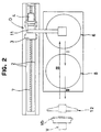
- the apparatus for transferring and setting assemblies of bead parts comprises a stocking part 6 for storing a number of bead part assemblies B vertically stacked in tiers through separators S, a collecting part 8 for emptied separators, arranged in the proximity of the stocking part 6 for the bead part assemblies, and a tire building machine V for thereon receiving the bead part assemblies B and building tires, and the arrangement is made such that transfer means D can be moved from one to the other of the bead part assembly stocking part 6, the emptied separator collecting part 8 and the tire building machine V.
- the transfer means D is provided with a horizontal unit R which can be driven to reciprocal motion along a pair of guide rails 2 installed on a mounting bed 1 fixed on a base E.
- the horizontal unit R has a base seat 3 at its bottom, which is slidable back and forth along the guide rails 2, and is driven to run by a driving motor 4 attached to the base seat 3, through a ball screw 7 mounted between the guide rails 2 as shown in Fig. 2.
- a stanchion 5 is provided, standing on the base seat 3, by which a vertical guide rail 9 is supported.
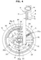
- a vertical unit H which has a base seat 10 adapted to go up or down along the guide rail 9 and which can be moved through the rotation of a ball screw (not shown) rotated by a driving motor M (Fig. 4). As shown in Fig. 4, an arm 11 extending in a horizontal direction is fixed to the base seat 10.
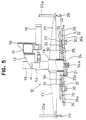
- a bifurcate bracket 13 is secured at an end portion of the arm 11 opposite the end at which it is fixed to the base seat 10, and to this bracket 13, a cylindrical bracket 14 is rotatably connected through a support shaft n.
- the bracket 14 can be driven to rotate about the support shaft n by a pair of cylinders 15 pivotally supported to the arm 11, and it is provided with holding means 12 as later to be detailed.
- the bracket 14 that is rotatably supported as above has a cylinder 16 provided on its top end, and a rod 17 extending from the cylinder 16 is inserted into the bracket 14, which rod 17 has a cylindrical center block 19 provided at its leading end through a universal joint 18.
- at least three arms 21 are fixed around the outer periphery of the center block 19, radially at constant intervals.
- an attraction pad 20 is attached as holding means for separators S, and the attraction pads 20 are adapted to move up and down as driven by lifting and lowering cylinders 20a.
- vacuum may be utilized or, in case the separators S comprise a ferromagnetic body, an electromagnet is effectively utilizable.
- a disk-shaped picker base 25 is fixed, and a cam plate 23 also of a disk shape is rotatably supported through a bearing 50 provided on the picker base 25.
- the cam plate 23 is formed with arc-shaped guide grooves 22, extending slantly in the radial direction and at constant intervals in the circumferential direction.
- a rotary actuator 24 is housed, which has a driving shaft 24a, to which an L-shaped rotary arm 31 is fixed, which in turn is connected through an arc-shaped groove 25a formed in the picker base 25 to the cam plate 23 to drive this cam plate 23 to rotate.
- a pair of guide rails 26 is radially arranged at each of the plurality of locations corresponding to the locations of the arms 21.
- Sliding bases 32 engage the guide rails 26, and cam followers 33 engageable with the guide grooves 22 of the cam plate 23 are mounted on the sliding bases 32.
- engaging claws 30 are fixed through grooves 26a formed along the pairs of guide rails 26.
- the engaging claws 30 constitute holding means for the bead part assembly B, which are provided at three or more points in the circumferential direction and which are moved to hold the bead part assembly B of a ring shape radially outwardly from the inner diameter side thereof.
- the distance detecting sensor 27 detects that the picker base 25 has approached a separator S and issues a detection signal to stop lowering of the holding means 12 and, at the same time, put into operation the lifting and lowering cylinders 20a, the attraction pads 20 and the rotary actuator 24.
- the picker base 25 is provided also with at least three stoppers 28 as shown in Fig. 9, which are arranged circumferentially at constant intervals. The stoppers 28 are adjustable with respect to their height positions and provided at their respective lower ends with a rotatable ball 29.
- the separator S comprises a ring-shaped separator body Sa, which has a plurality of notch portions 35 radially outwardly extending from a central open space portion thereof so that at the times of picking up of bead part assemblies B, its interference with engaging claws 30 can be avoided.
- the upper surface shown by 36 of the separator body Sa is formed with a concavo-convex pattern so that a bead part assembly B placed on the separator S can be prevented from intimately or closely attach onto the surface 36.
- the surface 36 is made a roughened one on account of the cacavo-convex pattern formed thereon as above, such roughened surface can be otherwise formed by forming a number of point-like recesses or projections.
- a recess 34 is formed as shown in Fig. 11 so that a bead part assembly B placed on a lower located separator S can be received in a non-contacting state on account of the recess 34.
- bead part assemblies B can be stored without the danger of impairing the unvulcanized bead fillers Bf which easily tend to undergo deformation.
- the separator body Sa is formed on its upper surface 36 with an annular peripheral edge portion 37 which has a flat and smooth surface so that attraction or suction by the attraction pads 20 can easily take place.
- the separator body Sa is formed with recesses 39 at a plurality of points (three points in the illustrated embodiment), at the prescribed intervals, on its upper surface in its outer peripheral edge portion and, on its underside surface, with projections 40 engageable in the recesses 39 by fitting.
- the recesses 39 and the projections 40 in combination constitute positioning means 38 for a number of separators S to be altogether piled in tiers, in both the radial and the circumferential directions. By the provision of such positioning means 38, a number of separators can be stacked in tiers always in a stable condition without dislocation relative to one another.
- the engaging claws 30 can without fail enter the notch portions 35 of separators S, whereby a secure picking up operation can be guaranteed.
- a displacement of for example the phase in the circumferential direction of bead part assemblies B (for example, a mutual displacement of joining points of bead fillers Bf) can be prevented from occurring during transportation of the bead part assemblies, so that the tire building operation can be carried out with the tire forming parts constantly positioned at their respective prescribed locations, whereby stabilization of the tire uniformity can be realized.
- the separator body Sa is in the form of a flat plate, so that the bead filler Bf is in an erect position around outer periphery of the bead core Bc.
- the upper surface 36 of the separator body Sa may be made an inclined surface.
- a restriction is applied in this case, depending on the particular size of the bead part assembly B. Modifications in this respect are within a range of design changes which can be readily derived by skilled persons in the art.
- the horizontal unit R is moved along the guide rails 2 to bring the transfer means D to a halt at the stocking or storing part 6 for the bead part assemblies, as shown in Fig. 1.
- the lifting and lowering cylinder 16 is actuated to have the rod 17 extended, and with the center block 19 held in a rotatable state, the vertical unit H is lowered.
- the holding means 12 is brought to a halt on top of the bead part assembly stocking part 6.
- the above lowering operation is carried out in a manner such that while it takes place at a high speed until the predetermined height position is reached, it is then switched to a low speed at a height position near the top of the bead part assembly stocking part 6.
- the separator S takes an inclined position at an angle of ⁇ ° relative to the horizon in the condition in which the holding means 12 is in contact with the top surface of the stocking part 6 as shown in Fig. 6, the holding means 12 can be pivoted through the universal joint 18 to follow the inclination at the angle ⁇ °.
- the plurality of engaging claws 30 can be always brought to a virtually parallel position to the separator S and a failure-free picking up of the bead part assembly B can be carried out.
- the rotary actuator 24 housed in the center block 19 starts operation to cause the cam plate 23 to rotate through the rotary arm 31.
- the engaging claws 30 move radially outwardly to engage the inner diametral periphery of a bead part assembly B and effect holding of this bead part assembly B as shown in Fig. 6.
- the plurality of attraction or suction pads 20 is brought to abut against the separator S through the operation of the lifting and lowering cylinder 20a and hold the separator S through attraction or suction.
- the holding means 12 of the transfer means D is lifted and, as shown by an arrow I in Fig. 1, moved to the emptied separator collecting part 8 and then down onto this collecting part 8.
- the suction or attraction of the separator S by the suction or attraction pads 20 is released, resulting in the separator S alone being left on top of the emptied separator collecing part 8.
- the upper surface 36 of the separator S comprises a roughened surface as earlier described, so that the separator S can easily leave the bead part assembly B.
- the holding means 12 of the transfer means D is moved in the direction shown by an arrow II in Fig. 1 to the tire building machine V.
- the rod 17 is now contracted by actuating the lifting and lowering cylinder 16 to bring the center block 19 to abut with its top surface against the underside surface of the bracket 14, whereby the holding means 12 is locked not to pivot.
- the holding means 12 is turned 90° by the cylinder 15 to its position facing the tire building machine V as shown in Fig. 3, and thereafter it is moved towards a bead loader Vb of the tire molding machine V and then stopped.
- the engaging claws 30 are retracted radially inwardly by actuating the rotary actuator 24 and the bead part assembly B is transferred and set on the bead loader Vb of the tire building machine V.
- the holding means 12 of the transfer means D is moved back to the bead part assembly storing part 6 as shown by an arrow III in Fig. 1 and, at the same time as this, the holding means 12 is turned 90° to take a downwardly facing position by actuating the cylinder 15.
- the above described operation steps are then repeated.
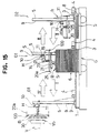
- Fig. 15 illustrates another embodiment of the present invention, which differs from the above described embodiment in respect of that the engaging claws 30 constituting holding means for bead part assemblies B and the suction or attraction pads 20 constituting holding means for separators S are provided separately to separate and mutually independent first transfer means D1 and second transfer means D2 respectively. Also, in the present embodiment, the bead part stocking or storing part 6 and the emptied separator collecting part 8 are provided on a movable wheeled carriage G.
- the first transfer means D1 has at least three engaging claws 30 provided thereto in a same manner as in the case of the transfer means D of the earlier described embodiment, and it is provided with pressing members 120 in place of the already described attraction or suction pads 20.
- the pressing members 120 are made of an elastic material such as rubber or the like, and operative so that when engaging claws 30 holding a bead part assembly B on a separator S are lifted, they press down the separator S in the direction opposite the direction of lifting through the operation of cilynders 20a and surely effect the separation away of the separator S.
- the above described pressing members can be utilized in the case of the earlier described first embodiment of the present invention, too, together with the afore-described attraction pads.
- the second transfer means D2 is provided on its outer peripheral portion with at least three attraction pads 20 alike the transfer means D of the earlier described embodiment and, as fixed to the lower end of the center block 19 at its central part, with a supporting plate 125 in place of the earlier described picker base 25, this supporting plate 125 being provided with distance detectig sensors and stoppers alike the picker base 25. Also, to the bracket 13 attached to the front side end of the arm 11, the bracket 14 is fixed so as not to be rotatable.
- the transfer means D1 operates in the first place to pick up a bead part assembly B at the bead part assembly stocking part 6, and then moves as shown by an arrow I to the location of the tire building machine V, at which it transfers the bead part assembly B onto the bead loader Vb.
- the second transfer means D2 moves as shown by an arrow II to the position of the bead part assembly stocking part 6, and after it has picked up a separator S, returns as shown by an arrow III to the position of the emptied separator collecting part 8 to perform collection of separators S.
- the first transfer means D1 returns as shown by an arrow IV to the position of the bead part assembly stocking part 6 and, after it has again picked up a bead part assembly B, moves as shown by the arrow I.
- first transfer means D1 and the second transfer means D2 operate alternately as described above, it becomes possible to supply bead part assemblies to the tire building machine at an enhanced operation efficiency and to further improve the tire building productivity. Also, collection of emptied separators can be effected at an enhanced operation efficiency.
- separators are picked up at and carried from the tire part assembly stocking part to an emptied separator collecting part by separator holding means, so that bead part assemblies stacked in tiers through separators can be supplied to the tire building machine at a high efficiency and the tire building productivity can be enhanced. Also, emptied separators can be collected highly efficiently.
- the method of and apparatus for transferring and setting bead part assemblies of tires bringing about the above described desirable results according to the present invention can be highly advantageously utilized in or for efficiently supplying bead part assemblies stacked in tiers through separators to a tire building machine.
Landscapes
- Engineering & Computer Science (AREA)
- Mechanical Engineering (AREA)
- Tyre Moulding (AREA)
Claims (19)
- Verfahren zum Transportieren und Absetzen von Wulstteilbaueinheiten (B) für Reifen, welches umfaßt:- Bereitstellen eines Wulstteilbaueinheit-Lagerteils (6), in dem eine Anzahl von Wulstteilbaueinheiten (B) mittels Separatoren (S) lagenweise vertikal gestapelt ist, eines Sammelteils (8) für geleerte Separatoren, das in der Nähe des Wulstteilbaueinheit-Sammelteils (6) angeordnet ist, einer Reifenkonfektioniermaschine (V), um die Wulstteilbaueinheiten (B) darauf zu empfangen, einer Wulstteilbaueinheit-Halteeinrichtung zum Aufnehmen von Wulstteilbaueinheiten und einer Separator-Halteeinrichtung zum Aufnehmen der Separatoren;- den Schritt, zu bewirken, daß die Wulstteilbaueinheit-Halteeinrichtung Wulstteilbaueinheiten jeweils einzeln vom Wulstteilbaueinheit-Lagerteil (6) aufnimmt und die aufgenommene Wulstteilbaueinheit (B) zur Reifenkonfektioniermaschine (V) trägt, und- zu bewirken, daß die Separator-Halteeinrichtung Separatoren (S) jeweils einzeln vom Wulstteilbaueinheit-Lagerteil (6) aufnimmt und den aufgenommenen Separator zum Sammelteil (8) für die geleerten Separatoren trägt; und- Bereitstellen der Wulstteilbaueinheit-Halteeinrichtung und der Separator-Halteeinrichtung auf einer gemeinsamen Transporteinrichtung (D);gekennzeichnet durch die Schritte:- Vorwärtsbewegen oder Zurückziehen einer Mehrzahl von Eingriffsklauen (30) in radialen Richtungen, welche in gleichen Abständen voneinander in Umfangsrichtung auf der Wulstteilbaueinheit-Halteeinrichtung der gemeinsamen Transporteinrichtung (D) angeordnet sind; und- Anheben oder Absenken einer Mehrzahl von Anziehungskissen (20) der Separator-Halteeinrichtung der gemeinsamen Transporteinrichtung (D).
- Verfahren nach Anspruch 1, dadurch gekennzeichnet, daß es den Schritt eines Drehens der Wulstteilbaueinheit-Halteeinrichtung der gemeinsamen Transporteinrichtung (D) aus einer nach unten weisenden Stellung in eine zur Seite hin weisende Stellung umfaßt, während die Transporteinrichtung zur Reifenkonfektioniermaschine hin bewegt wird.
- Verfahren zum Transportieren und Absetzen von Wulstteilbaueinheiten (B) für Reifen, welches umfaßt:- Bereitstellen eines Wulstteilbaueinheit-Lagerteils (6), in dem eine Anzahl von Wulstteilbaueinheiten (B) mittels Separatoren (S) lagenweise vertikal gestapelt ist, eines Sammelteils (8) für geleerte Separatoren, das in der Nähe des Wulstteilbaueinheit-Sammelteils (6) angeordnet ist, einer Reifenkonfektioniermaschine (V), um die Wulstteilbaueinheiten (B) darauf zu empfangen und Reifen zu konfektionieren, einer Wulstteilbaueinheit-Halteeinrichtung zum Aufnehmen von Wulstteilbaueinheiten und einer Separator-Halteeinrichtung zum Aufnehmen der Separatoren;gekennzeichnet durch die Schritte:- Vorwärtsbewegen oder Zurückziehen einer Mehrzahl von Eingriffsklauen (30) in radialen Richtungen, welche in gleichen Abständen voneinander in Umfangsrichtung auf der Wulstteilbaueinheit-Halteeinrichtung einer ersten Transporteinrichtung (D1) angeordnet sind;- Anheben oder Absenken einer Mehrzahl von Anziehungskissen (20) der Separator-Halteeinrichtung einer zweiten Transporteinrichtung (D2), die von der ersten Transporteinrichtung (D1) getrennt ist;- Bewirken, daß die erste Transporteinrichtung (D1) Wulstteilbaueinheiten jeweils einzeln vom Wulstteilbaueinheit-Lagerteil (6) aufnimmt und die aufgenommene Wulstteilbaueinheit (B) zur Reifenkonfektioniermaschine (V) trägt, und- Bewirken, daß die zweite Transporteinrichtung (D2) Separatoren (S) jeweils einzeln vom Wulstteilbaueinheit-Lagerteil (6) aufnimmt und den aufgenommenen Separator zum Sammelteil (8) für die geleerten Separatoren trägt.
- Verfahren nach Anspruch 3, dadurch gekennzeichnet, daß es den Schritt eines Drehens der Wulstteilbaueinheit-Halteeinrichtung der ersten Transporteinrichtung (D1) aus einer nach unten weisenden Stellung in eine zur Seite hin weisende Stellung umfaßt, während die Transporteinrichtung zur Reifenkonfektioniermaschine hin bewegt wird.
- Vorrichtung zum Transportieren und Absetzen von Wulstteilbaueinheiten für Reifen, welche umfaßt:- ein Wulstteilbaueinheit-Lagerteil (6), in dem eine Anzahl von Wulstteilbaueinheiten (B) mittels Separatoren (S) lagenweise vertikal gestapelt ist, ein in der Nähe des Wulstteilbaueinheit-Lagerteils (6) angeordnetes Sammelteil (8) für geleerte Separatoren, eine Reifenkonfektioniermaschine (V), um darauf die Wulstteilbaueinheiten (B) zu empfangen, eine Wulstteilbaueinheit-Halteeinrichtung (30) zum Aufnehmen von Wulstteilbaueinheiten (B), und eine Separator-Halteeinrichtung (20) zum Aufnehmen der Separatoren;- wobei die Wulstteilbaueinheit-Halteeinrichtung (30) angepaßt ist, um Wulstteilbaueinheiten (B) jeweils einzeln vom Wulstteilbaueinheit-Lagerteil (6) aufzunehmen und die aufgenommene Wulstteilbaueinheit (B) zur Reifenkonfektioniermaschine (V) zu tragen; und- wobei die Separator-Halteeinrichtung (20) angepaßt ist, um Separatoren (S) jeweils einzeln vom Wulstteilbaueinheit-Lagerteil (6) aufzunehmen und den aufgenommenen Separator zum Sammelteil (8) für die geleerten Separatoren zu tragen; wobei- die Wulstteilbaueinheit-Halteeinrichtung (30) und die Separator-Halteeinrichtung (20) an einer gemeinsamen Transporteinrichtung (D) vorgesehen und angepaßt sind, um gleichzeitig eine Wulstteilbaueinheit (B) und einen Separator (S) vom Wulstteilbaueinheit-Lagerteil (6) aufzunehmen;dadurch gekennzeichnet, daß- die Wulstteilbaueinheit-Halteeinrichtung aus einer Mehrzahl von Eingriffsklauen (30) strukturiert ist, die sich in radialen Richtungen vorwärtsbewegen oder zurückziehen können und in Umfangsrichtung in gleichen Abständen angeordnet sind; und- die Separator-Halteeinrichtung aus Anziehungskissen (20) strukturiert ist, welche angehoben oder abgesenkt werden können und radial auswärts von der Mehrzahl von Eingriffsklauen (30) der Wulstteilbaueinheit-Halteeinrichtung angeordnet sind.
- Vorrichtung zum Transportieren und Absetzen von Wulstteilbaueinheiten für Reifen, welche umfaßt:- ein Wulstteilbaueinheit-Lagerteil (6), in dem eine Anzahl von Wulstteilbaueinheiten (B) mittels Separatoren (S) lagenweise vertikal gestapelt ist, ein in der Nähe des Wulstteilbaueinheit-Lagerteils (6) angeordnetes Sammelteil (8) für geleerte Separatoren, eine Reifenkonfektioniermaschine (V), um darauf die Wulstteilbaueinheiten (B) zu empfangen, eine Wulstteilbaueinheit-Halteeinrichtung (30) zum Aufnehmen von Wulstteilbaueinheiten (B), und eine Separator-Halteeinrichtung (20) zum Aufnehmen der Separatoren;- wobei die Wulstteilbaueinheit-Halteeinrichtung (30) angepaßt ist, um Wulstteilbaueinheiten (B) jeweils einzeln vom Wulstteilbaueinheit-Lagerteil (6) aufzunehmen und die aufgenommene Wulstteilbaueinheit (B) zur Reifenkonfektioniermaschine (V) zu tragen; und- wobei die Separator-Halteeinrichtung (20) angepaßt ist, um Separatoren (S) jeweils einzeln vom Wulstteilbaueinheit-Lagerteil (6) aufzunehmen und den aufgenommenen Separator zum Sammelteil (8) für die geleerten Separatoren zu tragen;dadurch gekennzeichnet, daß- die Wulstteilbaueinheit-Halteeinrichtung (30) und die Separator-Halteeinrichtung (20) getrennt an einer ersten Transporteinrichtung (D1) bzw. einer zweiten Transporteinrichtung (D2) vorgesehen sind;- die Wulstteilbaueinheit-Halteeinrichtung aus einer Mehrzahl von Eingriffsklauen (30) strukturiert ist, die sich in radialen Richtungen vorwärtsbewegen oder zurückziehen können und in Umfangsrichtung in gleichen Abständen angeordnet sind; und- die Separator-Halteeinrichtung aus Anziehungskissen (20) strukturiert ist, welche angehoben oder abgesenkt werden können.
- Vorrichtung nach Anspruch 5, dadurch gekennzeichnet, daß die gemeinsame Transporteinrichtung (D) angepaßt ist, um sich vom Wulstteilbaueinheit-Lagerteil (6) über das Sammelteil (8) für die geleerten Separatoren zur Reifenkonfektioniermaschine (V) zu bewegen.
- Vorrichtung nach Anspruch 6, dadurch gekennzeichnet, daß:- die erste Transporteinrichtung (D1) angepaßt ist, um sich vom Wulstteilbaueinheit-Lagerteil (6) zur Reifenkonfektioniermaschine (V) zu bewegen; und- die zweite Transporteinrichtung (D2) angepaßt ist, um sich vom Wulstteilbaueinheit-Lagerteil (6) zum Sammelteil (8) für die geleerten Separatoren zu bewegen.
- Vorrichtung nach Anspruch 5, dadurch gekennzeichnet, daß die gemeinsame Transporteinrichtung (D) an einer Horizontaleinheit vorgesehen ist, die sich in horizontalen Richtungen hin und her bewegen läßt.
- Vorrichtung nach Anspruch 5, dadurch gekennzeichnet, daß die Wulstteilbaueinheit-Halteeinrichtung (30) und die Separator-Halteeinrichtung (20) beide zwischen einer nach unten weisenden Stellung und einer in seitlicher Richtung weisenden Stellung drehbar sind.
- Vorrichtung nach Anspruch 10, dadurch gekennzeichnet, daß die Wulstteilbaueinheit-Halteeinrichtung (30) und die Separator-Halteeinrichtung (20) beide schwenkbar sind oder unbeweglich fixiert werden können.
- Vorrichtung nach Anspruch 5, dadurch gekennzeichnet, daß das Wulstteilbaueinheit-Lagerteil (6) und das Sammelteil (8) für die geleerten Separatoren auf einem mit Rädern versehenen Wagen vorgesehen sind.
- Vorrichtung nach Anspruch 6, dadurch gekennzeichnet, daß die erste Transporteinrichtung (D1) und die zweite Transporteinrichtung (D2) getrennt auf Horizontaleinheiten angebracht sind, die sich in horizontalen Richtungen hin und her bewegen lassen.
- Vorrichtung nach Anspruch 6, dadurch gekennzeichnet, daß die Mehrzahl von Anziehungskissen (20) in Umfangsrichtung in gleichen Abständen angeordnet ist.
- Vorrichtung nach Anspruch 14, dadurch gekennzeichnet, daß:- die Wulstteilbaueinheit-Halteeinrichtung (30) zwischen einer nach unten weisenden Stellung und einer in seitlicher Richtung weisenden Stellung drehbar ist; und- die Separator-Halteeinrichtung (20) in einer nach unten weisenden Stellung fixiert ist.
- Vorrichtung nach Anspruch 13, dadurch gekennzeichnet, daß die Wulstteilbaueinheit-Halteeinrichtung (30) drehbar ist oder unbeweglich fixiert werden kann.
- Vorrichtung nach Anspruch 6, dadurch gekennzeichnet, daß das Wulstteilbaueinheit-Lagerteil (6) und das Sammelteil (8) für die geleerten Separatoren auf einem mit Rädern versehenen Wagen angebracht sind.
- Separator (S) für Wulstteilbaueinheiten (B) für Reifen, welcher einen Separatorkörper (Sa) in Form eines Rings (37) umfaßt,
dadurch gekennzeichnet, daß
während die Oberseite des Separatorkörpers eine konkav-konvex aufgerauhte Oberfläche umfaßt, die Unterseite oder Rückseite mit einer ringförmigen Ausnehmung (39) ausgebildet ist, um eine Wulstteilbaueinheit in einem Zustand aufzunehmen, in dem diese den Separatorkörper nicht berührt. - Separator nach Anspruch 18, dadurch gekennzeichnet, daß der Separatorkörper (Sa) an einer Mehrzahl von Stellen in der Nähe seines äußeren Umfangsrandes mit Eingriffsteilen (39) ausgebildet ist, die sich in einem aufgestapelten Zustand von Separatoren (S) mit den entsprechenden oder komplementären Eingriffsteilen (40) eines unmittelbar benachbarten Separatorkörpers (Sa) in Eingriff bringen lassen.
Applications Claiming Priority (7)
| Application Number | Priority Date | Filing Date | Title |
|---|---|---|---|
| JP3295766A JP2916832B2 (ja) | 1991-11-12 | 1991-11-12 | タイヤビード用セパレータ,タイヤビードの移載方法及びその装置 |
| JP295766/91 | 1991-11-12 | ||
| JP345194/91 | 1991-12-26 | ||
| JP03345194A JP3077003B2 (ja) | 1991-12-26 | 1991-12-26 | タイヤビードの移載方法及びその装置 |
| JP107595/92 | 1992-04-27 | ||
| JP10759592A JP3205382B2 (ja) | 1992-04-27 | 1992-04-27 | タイヤビードの移載装置 |
| PCT/JP1992/001466 WO1993009935A1 (fr) | 1991-11-12 | 1992-11-11 | Procede et dispositif pour le transfert de pieces de confection de talons de pneus |
Publications (3)
| Publication Number | Publication Date |
|---|---|
| EP0567652A1 EP0567652A1 (de) | 1993-11-03 |
| EP0567652A4 EP0567652A4 (en) | 1993-12-29 |
| EP0567652B1 true EP0567652B1 (de) | 1997-01-29 |
Family
ID=27311024
Family Applications (1)
| Application Number | Title | Priority Date | Filing Date |
|---|---|---|---|
| EP92923361A Expired - Lifetime EP0567652B1 (de) | 1991-11-12 | 1992-11-11 | Verfahren und vorrichtung zum zuführen der montageteile eines reifen-wulstes |
Country Status (5)
| Country | Link |
|---|---|
| US (1) | US5433815A (de) |
| EP (1) | EP0567652B1 (de) |
| KR (1) | KR0174759B1 (de) |
| DE (1) | DE69217201T2 (de) |
| WO (1) | WO1993009935A1 (de) |
Cited By (3)
| Publication number | Priority date | Publication date | Assignee | Title |
|---|---|---|---|---|
| WO2010021546A1 (en) * | 2008-08-21 | 2010-02-25 | Vmi Holland B.V. | Method and device for transferring and placing tyre beads and spacer to be used therefor |
| US8794288B2 (en) | 2008-08-21 | 2014-08-05 | Vmi Holland B.V. | Method for transferring and placing beads for tyres, device for carrying out such a method and spacer to be used in such a method and/or device |
| TWI630098B (zh) * | 2008-08-21 | 2018-07-21 | Vmi荷蘭公司 | 將用於輪胎之胎唇轉移和定位的方法,用於實行此方法的裝置以及用於此方法和/或裝置的分隔件 |
Families Citing this family (20)
| Publication number | Priority date | Publication date | Assignee | Title |
|---|---|---|---|---|
| KR100505806B1 (ko) * | 2002-01-14 | 2005-08-03 | 한국타이어 주식회사 | 비드 이송 및 방향 전환장치 |
| JP4256281B2 (ja) | 2004-02-24 | 2009-04-22 | 株式会社ブリヂストン | タイヤの製造方法およびビード部材供給装置 |
| US7963018B2 (en) | 2007-10-04 | 2011-06-21 | The Goodyear Tire & Rubber Company | Tire bead separation method and device |
| CN103171167A (zh) * | 2011-12-22 | 2013-06-26 | 软控股份有限公司 | 胎圈传递环及其传递方法 |
| CN103523530A (zh) * | 2013-10-14 | 2014-01-22 | 吴江市博众精工科技有限公司 | 一种产品吸取机构 |
| NL2012515B1 (en) * | 2014-03-27 | 2016-01-19 | Vmi Holland Bv | Unloading system and method for unloading a tire tread carrier. |
| GB2531072A (en) * | 2014-10-10 | 2016-04-13 | Shopatm B V | Vending machine and associated methods |
| CN104355101B (zh) * | 2014-10-22 | 2016-09-21 | 王贤淮 | 一种三维升降伸缩接料工作装置 |
| CN104384907B (zh) * | 2014-11-19 | 2017-01-18 | 苏州博众精工科技有限公司 | 一种方向可调的吸取机构 |
| CN105196583B (zh) * | 2015-10-28 | 2017-05-03 | 天津赛象科技股份有限公司 | 胎圈预置器行走定位装置 |
| CN107324014A (zh) * | 2016-04-28 | 2017-11-07 | 宁波胜克换向器有限公司 | 一种换向器压制工序的自动接料装置 |
| CN107777355B (zh) * | 2016-07-14 | 2019-06-28 | 南通迅达橡塑制造有限公司 | 一种塑料板抓取输送机构 |
| CN107215669A (zh) * | 2017-07-19 | 2017-09-29 | 江西迪迪工业智能设备有限公司 | 一种刮料装置及方法 |
| CN108466833B (zh) * | 2018-03-28 | 2020-01-07 | 江苏理工学院 | 一种送料装置 |
| CN108773098B (zh) * | 2018-05-30 | 2020-10-02 | 佛山市南海区广工大数控装备协同创新研究院 | 一种基于胎圈的柔性自动拆分机 |
| CN108861569B (zh) * | 2018-07-09 | 2022-05-03 | 合肥至信机械制造有限公司 | 一种钣金件气动机械手自动上料装置及其工作方式 |
| CN110316543B (zh) * | 2019-06-27 | 2021-10-01 | Tcl王牌电器(惠州)有限公司 | 一种面板翻转设备 |
| CN111571086A (zh) * | 2020-05-07 | 2020-08-25 | 安徽绪稻康建筑工程咨询有限公司 | 用于钣金焊接的辅助组件 |
| CN111571087A (zh) * | 2020-05-07 | 2020-08-25 | 安徽绪稻康建筑工程咨询有限公司 | 自动化多功能焊接平台 |
| NL2029785B1 (en) * | 2021-11-17 | 2023-06-12 | Vmi Holland Bv | Gripper for gripping a spacer, handling assembly comprising said gripper and method for transferring a spacer from a first station to a second station |
Family Cites Families (6)
| Publication number | Priority date | Publication date | Assignee | Title |
|---|---|---|---|---|
| JPS53140388A (en) * | 1977-05-13 | 1978-12-07 | Bridgestone Tire Co Ltd | Tire forming apparatus |
| SU845345A1 (ru) * | 1979-08-16 | 1982-05-07 | Всесоюзный Научно-Исследовательский И Конструкторский Институт По Оборудованию Для Шинной Промышленности | Устройство дл подачи бортовых крыльев к барабану дл сборки покрышек пневматических шин |
| JPS56162632A (en) * | 1980-01-31 | 1981-12-14 | Sumitomo Rubber Ind Ltd | Bead feeder |
| JPS5970547A (ja) * | 1982-10-15 | 1984-04-21 | Mitsubishi Heavy Ind Ltd | ラジアルタイヤの製造方法及び装置 |
| DE3247441A1 (de) * | 1982-12-22 | 1984-06-28 | Continental Gummi-Werke Ag, 3000 Hannover | Verfahren und vorrichtung zum herstellen von wulstkernen fuer luftreifen |
| JPH02175235A (ja) * | 1988-12-28 | 1990-07-06 | Yokohama Rubber Co Ltd:The | タイヤビードの自動供給方法及びその装置 |
-
1992
- 1992-11-11 WO PCT/JP1992/001466 patent/WO1993009935A1/ja not_active Ceased
- 1992-11-11 US US08/084,237 patent/US5433815A/en not_active Expired - Lifetime
- 1992-11-11 DE DE69217201T patent/DE69217201T2/de not_active Expired - Lifetime
- 1992-11-11 EP EP92923361A patent/EP0567652B1/de not_active Expired - Lifetime
- 1992-11-11 KR KR1019930701880A patent/KR0174759B1/ko not_active Expired - Lifetime
Cited By (5)
| Publication number | Priority date | Publication date | Assignee | Title |
|---|---|---|---|---|
| WO2010021546A1 (en) * | 2008-08-21 | 2010-02-25 | Vmi Holland B.V. | Method and device for transferring and placing tyre beads and spacer to be used therefor |
| NL2001903C (nl) * | 2008-08-21 | 2010-03-10 | Vmi Holland Bv | Werkwijze voor het overbrengen en plaatsen van hielsamenstellen voor banden, inrichting voor het uitvoeren van een dergelijke werkwijze en spacer te gebruiken in een dergelijke werkwijze en/of inrichting. |
| RU2476322C2 (ru) * | 2008-08-21 | 2013-02-27 | Вми Холланд Б.В. | Способ и устройство для перемещения и размещения ободов покрышек и используемая для этого проставка |
| US8794288B2 (en) | 2008-08-21 | 2014-08-05 | Vmi Holland B.V. | Method for transferring and placing beads for tyres, device for carrying out such a method and spacer to be used in such a method and/or device |
| TWI630098B (zh) * | 2008-08-21 | 2018-07-21 | Vmi荷蘭公司 | 將用於輪胎之胎唇轉移和定位的方法,用於實行此方法的裝置以及用於此方法和/或裝置的分隔件 |
Also Published As
| Publication number | Publication date |
|---|---|
| KR930703143A (ko) | 1993-11-29 |
| WO1993009935A1 (fr) | 1993-05-27 |
| DE69217201D1 (de) | 1997-03-13 |
| EP0567652A4 (en) | 1993-12-29 |
| KR0174759B1 (ko) | 1999-04-01 |
| EP0567652A1 (de) | 1993-11-03 |
| US5433815A (en) | 1995-07-18 |
| DE69217201T2 (de) | 1997-06-05 |
Similar Documents
| Publication | Publication Date | Title |
|---|---|---|
| EP0567652B1 (de) | Verfahren und vorrichtung zum zuführen der montageteile eines reifen-wulstes | |
| EP2328745B1 (de) | Verfahren und vorrichtung zum weiterleiten und anordnen von reifenwülsten und dafür zu verwendendes abstandsstück. | |
| CN115060741B (zh) | 一种基于视觉识别的自动化轮毂缺陷检测系统 | |
| JPH05301302A (ja) | タイヤビードの供給方法及びその装置 | |
| US8932420B2 (en) | Method for transferring and placing beads for tyres, device for carrying out such a method and spacer to be used in such a method and/or device | |
| US3757966A (en) | Palletizing apparatus | |
| CN110668150B (zh) | 一种膜盘搬运设备 | |
| US5746964A (en) | Loading system and method for a tire vulcanizing machine | |
| US4594768A (en) | Trimming ceramic flatware | |
| US5443358A (en) | Indexing part loader | |
| US4462776A (en) | Tire withdrawal arrangement | |
| JPH05212815A (ja) | タイヤビードの移載方法及びその装置 | |
| JP2916832B2 (ja) | タイヤビード用セパレータ,タイヤビードの移載方法及びその装置 | |
| CN114290607A (zh) | 一种塑胶软管注头生产设备 | |
| JP4541505B2 (ja) | タイヤ成形におけるビードの自動供給装置及び自動供給方法 | |
| CN211807986U (zh) | 一种胎面自动供料装置 | |
| CN111196039B (zh) | 贴标合盖设备 | |
| CN110615145B (zh) | 面膜自动灌装生产线 | |
| JP3177780B2 (ja) | ビード取出し整列保管装置 | |
| US5206031A (en) | Vehicle tire loading-unloading device | |
| CN117583784A (zh) | 一种热水器内胆生产用的挂板焊接机及控制方法 | |
| CN111891475A (zh) | 一种奶茶杯自动搬运系统 | |
| CN213704939U (zh) | 一种晶圆片打标机的定位机构 | |
| CN114311498A (zh) | 一种塑胶软管注头生产方法 | |
| CN216708138U (zh) | 一种用于塑胶软管的注头生产线 |
Legal Events
| Date | Code | Title | Description |
|---|---|---|---|
| PUAI | Public reference made under article 153(3) epc to a published international application that has entered the european phase |
Free format text: ORIGINAL CODE: 0009012 |
|
| AK | Designated contracting states |
Kind code of ref document: A1 Designated state(s): DE NL |
|
| 17P | Request for examination filed |
Effective date: 19931013 |
|
| A4 | Supplementary search report drawn up and despatched |
Effective date: 19931111 |
|
| AK | Designated contracting states |
Kind code of ref document: A4 Designated state(s): DE NL |
|
| RAP1 | Party data changed (applicant data changed or rights of an application transferred) |
Owner name: MITSUBISHI JUKOGYO KABUSHIKI KAISHA Owner name: THE YOKOHAMA RUBBER CO., LTD. |
|
| K1C1 | Correction of patent application (title page) published |
Effective date: 19931103 |
|
| 17Q | First examination report despatched |
Effective date: 19950217 |
|
| GRAG | Despatch of communication of intention to grant |
Free format text: ORIGINAL CODE: EPIDOS AGRA |
|
| GRAH | Despatch of communication of intention to grant a patent |
Free format text: ORIGINAL CODE: EPIDOS IGRA |
|
| GRAH | Despatch of communication of intention to grant a patent |
Free format text: ORIGINAL CODE: EPIDOS IGRA |
|
| GRAA | (expected) grant |
Free format text: ORIGINAL CODE: 0009210 |
|
| AK | Designated contracting states |
Kind code of ref document: B1 Designated state(s): DE NL |
|
| REF | Corresponds to: |
Ref document number: 69217201 Country of ref document: DE Date of ref document: 19970313 |
|
| PLBE | No opposition filed within time limit |
Free format text: ORIGINAL CODE: 0009261 |
|
| STAA | Information on the status of an ep patent application or granted ep patent |
Free format text: STATUS: NO OPPOSITION FILED WITHIN TIME LIMIT |
|
| 26N | No opposition filed | ||
| PGFP | Annual fee paid to national office [announced via postgrant information from national office to epo] |
Ref country code: DE Payment date: 20101104 Year of fee payment: 19 |
|
| PGFP | Annual fee paid to national office [announced via postgrant information from national office to epo] |
Ref country code: NL Payment date: 20111122 Year of fee payment: 20 |
|
| REG | Reference to a national code |
Ref country code: DE Ref legal event code: R071 Ref document number: 69217201 Country of ref document: DE |
|
| REG | Reference to a national code |
Ref country code: DE Ref legal event code: R071 Ref document number: 69217201 Country of ref document: DE |
|
| REG | Reference to a national code |
Ref country code: NL Ref legal event code: V4 Effective date: 20121111 |