EP0566782B1 - Vorrichtung zum Reinigen von Maschinenreihen - Google Patents
Vorrichtung zum Reinigen von Maschinenreihen Download PDFInfo
- Publication number
- EP0566782B1 EP0566782B1 EP92122026A EP92122026A EP0566782B1 EP 0566782 B1 EP0566782 B1 EP 0566782B1 EP 92122026 A EP92122026 A EP 92122026A EP 92122026 A EP92122026 A EP 92122026A EP 0566782 B1 EP0566782 B1 EP 0566782B1
- Authority
- EP
- European Patent Office
- Prior art keywords
- equipment
- slider
- blower
- exhibits
- connector stubs
- Prior art date
- Legal status (The legal status is an assumption and is not a legal conclusion. Google has not performed a legal analysis and makes no representation as to the accuracy of the status listed.)
- Expired - Lifetime
Links
- 238000004140 cleaning Methods 0.000 title claims description 9
- 239000004753 textile Substances 0.000 claims description 9
- 238000009987 spinning Methods 0.000 description 6
- 238000007664 blowing Methods 0.000 description 4
- 238000004804 winding Methods 0.000 description 2
- 238000011109 contamination Methods 0.000 description 1
- 238000007789 sealing Methods 0.000 description 1
- 230000007704 transition Effects 0.000 description 1
Images
Classifications
-
- D—TEXTILES; PAPER
- D01—NATURAL OR MAN-MADE THREADS OR FIBRES; SPINNING
- D01H—SPINNING OR TWISTING
- D01H11/00—Arrangements for confining or removing dust, fly or the like
- D01H11/005—Arrangements for confining or removing dust, fly or the like with blowing and/or suction devices
- D01H11/006—Arrangements for confining or removing dust, fly or the like with blowing and/or suction devices travelling along the machines
-
- B—PERFORMING OPERATIONS; TRANSPORTING
- B08—CLEANING
- B08B—CLEANING IN GENERAL; PREVENTION OF FOULING IN GENERAL
- B08B5/00—Cleaning by methods involving the use of air flow or gas flow
- B08B5/02—Cleaning by the force of jets, e.g. blowing-out cavities
Definitions
- the invention relates to a device for cleaning rows of textile machines according to the preamble of claim 1.
- the device has the disadvantage that compressed air is always applied to one of the two hoses; there is no possibility of separating both hoses from the compressed air source. Furthermore, only two compressed air hoses can be connected to the distribution station.
- DE-GM 85 08 228 describes a cleaning device which can be moved along textile machines and has a fan on which at least two hoses are arranged, and a distributor box for distributing the blown air to these two hoses. Inside the distribution box is a flap with a horizontal swivel axis, which directs the blown air to one of several blow hoses connected to the distribution box.
- One of the blow hoses is used for blowing one winding machine, the other for blowing a spinning machine and a further blow hose is provided for blowing the whirl flaps of a spinning machine.
- a disadvantage of this device is that the distribution box must be very high due to the arrangement of the flaps, and the number of ventable hoses is limited to three. Finally, no position is provided in which none of the hoses is ventilated.
- DE 36 18 934 A1 describes a device for cleaning textile machines with a fan guided above the textile machines, to the pressure side of which two vertically extending blow hoses are connected via a distributor box, which have different openings directed towards the machine.
- An air guide element is arranged in the distribution box, which directs the blown air to one or the other blow hose.
- This air guide element is a flat sheet which represents a slide and is arranged inside the distribution box above the support openings to which the blow hoses are connected. In one position of this sheet the one nozzle is covered and in the other position the other nozzle and thus the blow hose arranged there is shut down.
- the arrangement allows the simultaneous closure of all air hoses, but only if their number is not too high. The arrangement can no longer be used if there are significantly more than three blown air hoses.
- the air baffle must be moved by an electric motor, since it is not manually accessible within the distribution box.
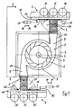
- the device essentially comprises a blower 1, a distributor station 2 and a flexible hose 3 connecting the blower 1 to the distributor station 2.
- the blower 1 has an outer housing 4, in which a fan housing 5 is arranged.
- the fan housing 5 contains an impeller 6, which is mounted centrally in the fan housing 5 and rotates about an axis 7 running perpendicular to the plane of the drawing in FIG.
- the wall of the fan housing 5 extends over a wide area 8 at a constant distance from the circumference of the impeller 6. This distance increases continuously in the area of the air outlet 9, the inner wall 10 of which emerges from the wall of the fan housing 5.
- the air duct 9 ends in the wall of the outer housing 4.
- a flexible hose 3 is connected to the air duct 9, which extends the air duct 9 to the outside.
- the flexible hose 3 connects the blower 1 to the distribution station 2.
- the distribution station 2 has a carrier plate 11, three connecting pieces 12, 13 and 14 and a slide 16 provided with a handle 15.
- An electrical adjustment unit 17 is arranged on the handle 15 of the slide 16. Blow hoses for cleaning the machine parts are connected to the connecting pieces 12, 13 and 14.
- a further distribution station 2 ' is arranged symmetrically with respect to the axis of rotation 7 of the impeller 6.
- the components of this second Distribution station 2 ' that is, the support plate 11', the three connecting pieces 12 ', 13' and 14 ', the slide 16' with the handle 15 'and the electrical adjustment unit 17' are identical to the components provided with the same reference numbers, but without a line the distributor station 2.
- the elements of the blower 1 assigned to the second distributor station 2 ' are also provided with crossed reference numerals.
- a second distributor station 2 ' is advantageous if the fan 1 is arranged above the machine row, the axis 7 of the impeller 6 running vertically. In this case, one side of the machine row can be cleaned with the hoses connected to the distribution station 2 and the other side with the hoses connected to the distribution station 2 '.
- the description of the structure and function of the distribution station 2 also applies analogously to the distribution station 2 '.
- the carrier plate 11 of the distribution station 2 stores the three connecting pieces 12, 13 and 14 in a through hole each.
- the slide 16 rests and is displaceable in the direction of the linear row of the through bores supporting the connecting pieces 12, 13 and 14.
- the slider 16 also has a through hole which, when it is moved, successively coincides with the three through holes in the carrier plate 11.
- the flexible hose 3, which connects the slider 16 to the air duct 9 of the blower 1, is attached to the side of the slider 16 facing away from the carrier plate 11 in a sealing manner and in connection with the through bore of the slider 16.
- the device works as follows:
- the air flows through the flexible hose 3 and passes through the bore of the Slider 16 and one of the through holes of the support plate 11 in one of the connecting pieces 12, 13 or 14.
- the position of the slider 16 shown in FIG. 1 connects the flexible hose 3 to the connecting piece 13. If the hose 3 is to be connected to the connecting piece 12, it must be connected the slider 16 can be moved in the direction of the arrow 18, which can be done either manually by actuating the handle 15 or by an electric motor by actuating the electric drive unit 17.
- the flexible hose 3 reaches position 3A, which is shown in broken lines in FIG. 1, and is connected to the connecting piece 12. If you want a connection of the flexible hose 3 to the connecting piece 14, you move the slider 16 in an analogous manner in the direction of arrow 19.
- the slide 16 can also be brought into a position in which the flexible hose 3 is not connected to any of the through holes in the carrier plate 11, but is closed off by the carrier plate 11 becomes. In this position of the slide 16, no air is conveyed and the hoses connected to the connecting pieces 12, 13 and 14 can be changed or cleaned.
- the slide is designed so large that it covers the through holes which are not currently pressurized with compressed air in order to prevent the flight in the spinning mill from settling in the corresponding hoses.
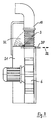
- FIG. 2 A further development of the device is shown schematically in FIG. 2. if it it is desired to apply vacuum to the hoses connected to the connecting pieces 12, 13 and 14, so if air is to be sucked in through these hoses, the flexible hose 3 is on its side facing the pressure side of the blower 1, i.e. at the transition from air duct 9 to flexible hose 3, attached to a further slide 20, by actuating the flexible hose 3 can be connected to the suction side of the blower 21.
- the slide 20 shown in Figure 2 can be moved along the double arrow 22, the suction position is shown in dashed lines.
- the flight blown off by the machine parts is then fed to the suction openings and can be filtered out.
Landscapes
- Engineering & Computer Science (AREA)
- Mechanical Engineering (AREA)
- Textile Engineering (AREA)
- Spinning Or Twisting Of Yarns (AREA)
- Preliminary Treatment Of Fibers (AREA)
Applications Claiming Priority (2)
| Application Number | Priority Date | Filing Date | Title |
|---|---|---|---|
| DE4213120 | 1992-04-21 | ||
| DE4213120A DE4213120C1 (enExample) | 1992-04-21 | 1992-04-21 |
Publications (3)
| Publication Number | Publication Date |
|---|---|
| EP0566782A2 EP0566782A2 (de) | 1993-10-27 |
| EP0566782A3 EP0566782A3 (en) | 1993-11-24 |
| EP0566782B1 true EP0566782B1 (de) | 1995-08-09 |
Family
ID=6457173
Family Applications (1)
| Application Number | Title | Priority Date | Filing Date |
|---|---|---|---|
| EP92122026A Expired - Lifetime EP0566782B1 (de) | 1992-04-21 | 1992-12-28 | Vorrichtung zum Reinigen von Maschinenreihen |
Country Status (4)
| Country | Link |
|---|---|
| US (1) | US5367738A (enExample) |
| EP (1) | EP0566782B1 (enExample) |
| DE (2) | DE4213120C1 (enExample) |
| ES (1) | ES2078639T3 (enExample) |
Families Citing this family (1)
| Publication number | Priority date | Publication date | Assignee | Title |
|---|---|---|---|---|
| CN104338710B (zh) * | 2014-10-08 | 2016-08-24 | 新昌县奥泰机械制造有限公司 | 清洁机外部自清理装置 |
Family Cites Families (7)
| Publication number | Priority date | Publication date | Assignee | Title |
|---|---|---|---|---|
| FR1338371A (fr) * | 1962-06-26 | 1963-09-27 | Perfectionnement aux installations de nettoyage de machines par ventilateur-voyageur | |
| US3375539A (en) * | 1964-09-25 | 1968-04-02 | Grinnell Corp | Traveling overhead textile machine cleaner |
| US3276065A (en) * | 1964-11-19 | 1966-10-04 | Bahnson Co | Traveling cleaner for textile machines |
| JPS6052217B2 (ja) * | 1983-07-11 | 1985-11-18 | 村田機械株式会社 | 精紡ワインダの風綿除去システム |
| DE8508228U1 (de) * | 1985-03-20 | 1985-05-02 | Ernst Jacobi & Co Kg, 8900 Augsburg | Längs Textilmaschinen verfahrbare Reinigungsvorrichtung |
| DE3618934A1 (de) * | 1986-06-05 | 1987-12-10 | Jacobi E & Co Kg | Vorrichtung zum reinigen von textilmaschinen |
| DE3738582A1 (de) * | 1987-11-13 | 1989-05-24 | Jacobi E & Co Kg | Vorrichtung zum verteilen der blasluft bei einer reinigungsvorrichtung fuer textilmaschinen |
-
1992
- 1992-04-21 DE DE4213120A patent/DE4213120C1/de not_active Expired - Fee Related
- 1992-12-28 ES ES92122026T patent/ES2078639T3/es not_active Expired - Lifetime
- 1992-12-28 EP EP92122026A patent/EP0566782B1/de not_active Expired - Lifetime
- 1992-12-28 DE DE59203234T patent/DE59203234D1/de not_active Expired - Fee Related
-
1993
- 1993-02-17 US US08/018,512 patent/US5367738A/en not_active Expired - Fee Related
Also Published As
| Publication number | Publication date |
|---|---|
| ES2078639T3 (es) | 1995-12-16 |
| EP0566782A2 (de) | 1993-10-27 |
| EP0566782A3 (en) | 1993-11-24 |
| US5367738A (en) | 1994-11-29 |
| DE4213120C1 (enExample) | 1993-06-17 |
| DE59203234D1 (de) | 1995-09-14 |
Similar Documents
| Publication | Publication Date | Title |
|---|---|---|
| EP0344417B1 (de) | Vorrichtung zum Transportieren von Flaschen | |
| EP3459642B1 (de) | Pulverbeschichtungsanlage zum beschichten eines werkstücks mit beschichtungspulver | |
| DE4425863A1 (de) | Saug- und Blasvorrichtung | |
| DE10101366A1 (de) | Sprühbeschichtungs-Pulverzentrum | |
| DE69201220T2 (de) | Elektrostatische Farbspritzanlage für Pulverbeschichtungsmaterial. | |
| EP0192014A1 (de) | Reinigungsgerät für Textilmaschinen | |
| DE19940333B4 (de) | Anlage für die Herstellung einer Spinnvliesbahn aus Kunststoffilamenten | |
| CH682085A5 (enExample) | ||
| DE2658752C2 (de) | Offenend-Spinnmaschine mit Mitteln zum Aufnehmen und Abführen abgeschiedener Verunreinigungen | |
| DE2264299A1 (de) | Vorrichtung zum abscheiden von aufgeloesten faserflocken aus einem foerderluftstrom | |
| DE4131287A1 (de) | Pulver-spruehbeschichtungsanlage | |
| EP0566782B1 (de) | Vorrichtung zum Reinigen von Maschinenreihen | |
| DE2518522A1 (de) | Farhbare pneumatische vorrichtung zum absaugen und abblasen von faserflug bei textilmaschinen | |
| DE3853119T2 (de) | In einem Bogen von 360 Grad arbeitende Flaschenwaschmaschine mit verlängerten Mitnehmerschaufeln. | |
| DE8809870U1 (de) | Vorrichtung zum Ablegen eines textilen Faserbandes in eine Kanne | |
| DE2221117C3 (de) | Pneumatische Spinnmaschinen-Reinigungsvorrichtung | |
| EP1123747A2 (de) | Pulverbeschichtungsanlage | |
| DE102006022897B4 (de) | Verfahren zur Durchführung eines Reinigungsvorganges und Vorrichtung zur Durchführung des Verfahrens | |
| WO1998035763A1 (de) | Bepuderungsanlage | |
| EP0565780A2 (de) | Reinigungsanlage für Textilmaschinen | |
| DE4009878C2 (de) | Luftsteuereinrichtung einer Spinnmaschine | |
| DE2924351C2 (enExample) | ||
| DE3727651A1 (de) | Vorrichtung zur waermebehandlung von warenbahnen, insbesondere textilbahnen | |
| DE10164724B4 (de) | Vorrichtung zum Wenden einer Bahn | |
| DE3001729A1 (de) | Stofflegemaschine |
Legal Events
| Date | Code | Title | Description |
|---|---|---|---|
| PUAI | Public reference made under article 153(3) epc to a published international application that has entered the european phase |
Free format text: ORIGINAL CODE: 0009012 |
|
| PUAL | Search report despatched |
Free format text: ORIGINAL CODE: 0009013 |
|
| AK | Designated contracting states |
Kind code of ref document: A2 Designated state(s): CH DE ES FR GB GR IT LI NL |
|
| AK | Designated contracting states |
Kind code of ref document: A3 Designated state(s): CH DE ES FR GB GR IT LI NL |
|
| 17P | Request for examination filed |
Effective date: 19940307 |
|
| 17Q | First examination report despatched |
Effective date: 19950125 |
|
| GRAA | (expected) grant |
Free format text: ORIGINAL CODE: 0009210 |
|
| AK | Designated contracting states |
Kind code of ref document: B1 Designated state(s): CH DE ES FR GB GR IT LI NL |
|
| PG25 | Lapsed in a contracting state [announced via postgrant information from national office to epo] |
Ref country code: NL Free format text: LAPSE BECAUSE OF FAILURE TO SUBMIT A TRANSLATION OF THE DESCRIPTION OR TO PAY THE FEE WITHIN THE PRESCRIBED TIME-LIMIT Effective date: 19950809 Ref country code: GR Free format text: LAPSE BECAUSE OF FAILURE TO SUBMIT A TRANSLATION OF THE DESCRIPTION OR TO PAY THE FEE WITHIN THE PRESCRIBED TIME-LIMIT Effective date: 19950809 Ref country code: GB Effective date: 19950809 |
|
| REF | Corresponds to: |
Ref document number: 59203234 Country of ref document: DE Date of ref document: 19950914 |
|
| ITF | It: translation for a ep patent filed | ||
| ET | Fr: translation filed | ||
| REG | Reference to a national code |
Ref country code: ES Ref legal event code: FG2A Ref document number: 2078639 Country of ref document: ES Kind code of ref document: T3 |
|
| NLV1 | Nl: lapsed or annulled due to failure to fulfill the requirements of art. 29p and 29m of the patents act | ||
| GBV | Gb: ep patent (uk) treated as always having been void in accordance with gb section 77(7)/1977 [no translation filed] |
Effective date: 19950809 |
|
| PLBE | No opposition filed within time limit |
Free format text: ORIGINAL CODE: 0009261 |
|
| STAA | Information on the status of an ep patent application or granted ep patent |
Free format text: STATUS: NO OPPOSITION FILED WITHIN TIME LIMIT |
|
| 26N | No opposition filed | ||
| PGFP | Annual fee paid to national office [announced via postgrant information from national office to epo] |
Ref country code: CH Payment date: 19971223 Year of fee payment: 6 |
|
| PGFP | Annual fee paid to national office [announced via postgrant information from national office to epo] |
Ref country code: ES Payment date: 19971231 Year of fee payment: 6 |
|
| PGFP | Annual fee paid to national office [announced via postgrant information from national office to epo] |
Ref country code: DE Payment date: 19980204 Year of fee payment: 6 |
|
| PGFP | Annual fee paid to national office [announced via postgrant information from national office to epo] |
Ref country code: FR Payment date: 19980618 Year of fee payment: 6 |
|
| PG25 | Lapsed in a contracting state [announced via postgrant information from national office to epo] |
Ref country code: LI Free format text: LAPSE BECAUSE OF NON-PAYMENT OF DUE FEES Effective date: 19981231 Ref country code: CH Free format text: LAPSE BECAUSE OF NON-PAYMENT OF DUE FEES Effective date: 19981231 |
|
| REG | Reference to a national code |
Ref country code: CH Ref legal event code: PL |
|
| PG25 | Lapsed in a contracting state [announced via postgrant information from national office to epo] |
Ref country code: FR Free format text: LAPSE BECAUSE OF NON-PAYMENT OF DUE FEES Effective date: 19990831 |
|
| REG | Reference to a national code |
Ref country code: FR Ref legal event code: ST |
|
| PG25 | Lapsed in a contracting state [announced via postgrant information from national office to epo] |
Ref country code: DE Free format text: LAPSE BECAUSE OF NON-PAYMENT OF DUE FEES Effective date: 19991001 |
|
| PG25 | Lapsed in a contracting state [announced via postgrant information from national office to epo] |
Ref country code: ES Free format text: LAPSE BECAUSE OF NON-PAYMENT OF DUE FEES Effective date: 19991229 |
|
| REG | Reference to a national code |
Ref country code: ES Ref legal event code: FD2A Effective date: 20000114 |
|
| PG25 | Lapsed in a contracting state [announced via postgrant information from national office to epo] |
Ref country code: IT Free format text: LAPSE BECAUSE OF NON-PAYMENT OF DUE FEES;WARNING: LAPSES OF ITALIAN PATENTS WITH EFFECTIVE DATE BEFORE 2007 MAY HAVE OCCURRED AT ANY TIME BEFORE 2007. THE CORRECT EFFECTIVE DATE MAY BE DIFFERENT FROM THE ONE RECORDED. Effective date: 20051228 |