EP0566767B1 - Installation de chauffage de carburant - Google Patents
Installation de chauffage de carburant Download PDFInfo
- Publication number
- EP0566767B1 EP0566767B1 EP92106966A EP92106966A EP0566767B1 EP 0566767 B1 EP0566767 B1 EP 0566767B1 EP 92106966 A EP92106966 A EP 92106966A EP 92106966 A EP92106966 A EP 92106966A EP 0566767 B1 EP0566767 B1 EP 0566767B1
- Authority
- EP
- European Patent Office
- Prior art keywords
- fuel
- heating
- filter
- heating apparatus
- chamber
- Prior art date
- Legal status (The legal status is an assumption and is not a legal conclusion. Google has not performed a legal analysis and makes no representation as to the accuracy of the status listed.)
- Expired - Lifetime
Links
- 238000010438 heat treatment Methods 0.000 title claims description 95
- 239000000446 fuel Substances 0.000 title claims description 77
- 239000002828 fuel tank Substances 0.000 claims description 31
- 238000009413 insulation Methods 0.000 claims description 3
- 238000002485 combustion reaction Methods 0.000 claims description 2
- 230000000063 preceeding effect Effects 0.000 claims 2
- 239000000295 fuel oil Substances 0.000 claims 1
- 238000011045 prefiltration Methods 0.000 description 11
- 239000002283 diesel fuel Substances 0.000 description 7
- 239000012188 paraffin wax Substances 0.000 description 6
- 239000000155 melt Substances 0.000 description 4
- 230000000694 effects Effects 0.000 description 3
- 238000004140 cleaning Methods 0.000 description 2
- 238000001914 filtration Methods 0.000 description 2
- 238000002347 injection Methods 0.000 description 2
- 239000007924 injection Substances 0.000 description 2
- 230000001105 regulatory effect Effects 0.000 description 2
- 230000007812 deficiency Effects 0.000 description 1
- 238000010616 electrical installation Methods 0.000 description 1
- 239000003344 environmental pollutant Substances 0.000 description 1
- 239000007789 gas Substances 0.000 description 1
- 239000012535 impurity Substances 0.000 description 1
- 238000009434 installation Methods 0.000 description 1
- 238000004519 manufacturing process Methods 0.000 description 1
- 238000000034 method Methods 0.000 description 1
- 238000002156 mixing Methods 0.000 description 1
- 239000003208 petroleum Substances 0.000 description 1
- 231100000719 pollutant Toxicity 0.000 description 1
- 239000000243 solution Substances 0.000 description 1
- 238000009423 ventilation Methods 0.000 description 1
Images


Classifications
-
- B—PERFORMING OPERATIONS; TRANSPORTING
- B60—VEHICLES IN GENERAL
- B60K—ARRANGEMENT OR MOUNTING OF PROPULSION UNITS OR OF TRANSMISSIONS IN VEHICLES; ARRANGEMENT OR MOUNTING OF PLURAL DIVERSE PRIME-MOVERS IN VEHICLES; AUXILIARY DRIVES FOR VEHICLES; INSTRUMENTATION OR DASHBOARDS FOR VEHICLES; ARRANGEMENTS IN CONNECTION WITH COOLING, AIR INTAKE, GAS EXHAUST OR FUEL SUPPLY OF PROPULSION UNITS IN VEHICLES
- B60K15/00—Arrangement in connection with fuel supply of combustion engines or other fuel consuming energy converters, e.g. fuel cells; Mounting or construction of fuel tanks
- B60K15/03—Fuel tanks
-
- F—MECHANICAL ENGINEERING; LIGHTING; HEATING; WEAPONS; BLASTING
- F02—COMBUSTION ENGINES; HOT-GAS OR COMBUSTION-PRODUCT ENGINE PLANTS
- F02M—SUPPLYING COMBUSTION ENGINES IN GENERAL WITH COMBUSTIBLE MIXTURES OR CONSTITUENTS THEREOF
- F02M31/00—Apparatus for thermally treating combustion-air, fuel, or fuel-air mixture
- F02M31/02—Apparatus for thermally treating combustion-air, fuel, or fuel-air mixture for heating
- F02M31/12—Apparatus for thermally treating combustion-air, fuel, or fuel-air mixture for heating electrically
- F02M31/125—Fuel
-
- F—MECHANICAL ENGINEERING; LIGHTING; HEATING; WEAPONS; BLASTING
- F02—COMBUSTION ENGINES; HOT-GAS OR COMBUSTION-PRODUCT ENGINE PLANTS
- F02B—INTERNAL-COMBUSTION PISTON ENGINES; COMBUSTION ENGINES IN GENERAL
- F02B3/00—Engines characterised by air compression and subsequent fuel addition
- F02B3/06—Engines characterised by air compression and subsequent fuel addition with compression ignition
-
- F—MECHANICAL ENGINEERING; LIGHTING; HEATING; WEAPONS; BLASTING
- F02—COMBUSTION ENGINES; HOT-GAS OR COMBUSTION-PRODUCT ENGINE PLANTS
- F02D—CONTROLLING COMBUSTION ENGINES
- F02D2200/00—Input parameters for engine control
- F02D2200/02—Input parameters for engine control the parameters being related to the engine
- F02D2200/06—Fuel or fuel supply system parameters
- F02D2200/0606—Fuel temperature
-
- Y—GENERAL TAGGING OF NEW TECHNOLOGICAL DEVELOPMENTS; GENERAL TAGGING OF CROSS-SECTIONAL TECHNOLOGIES SPANNING OVER SEVERAL SECTIONS OF THE IPC; TECHNICAL SUBJECTS COVERED BY FORMER USPC CROSS-REFERENCE ART COLLECTIONS [XRACs] AND DIGESTS
- Y02—TECHNOLOGIES OR APPLICATIONS FOR MITIGATION OR ADAPTATION AGAINST CLIMATE CHANGE
- Y02T—CLIMATE CHANGE MITIGATION TECHNOLOGIES RELATED TO TRANSPORTATION
- Y02T10/00—Road transport of goods or passengers
- Y02T10/10—Internal combustion engine [ICE] based vehicles
- Y02T10/12—Improving ICE efficiencies
Definitions
- the invention relates to a fuel heating device according to the preamble of claim 1, as known from DE-A-3 120 960.
- German patent application DE 3404817 A1 the regulation of fuel delivery, preferably of diesel fuel, is known, which is carried out by three radiators, attached in the fuel tank, in the pre-filter of the backing pump and in the main filter.
- the disadvantage of this heating of the frozen fuel is that the heating element is installed in the fuel tank in the coarse filter, which is attached to the bottom of the fuel tank together with the suction line, which causes frequent clogging of the filter and the line due to impurities, but at the same time insufficient amounts heated by fuel, which are absolutely necessary for filling the main filter and thus for the engine to function properly.
- Another disadvantage of this known heating is that the pressure and high pressure lines are not thermally insulated, which means that the temperatures in all lines are not constantly the same.
- Another disadvantage is that when changing the filter or changing the filter insert in the fuel tank, in the backing pump and in the main filter, the wire heating elements are thrown away together with them, which a be brought and are printed in the outer edge of the filter insert.
- Yet another disadvantage is that the wire heating elements are often damaged and destroyed during the assembly and regular cleaning of the filters and filter inserts. It is also a disadvantage that this method of heating frozen fuel is very demanding and expensive.
- the fuel heating device consisting of the tubular heating element attached to the bottom of the vertical heating chamber in the fuel tank, from the heating element attached to the bottom of the prefilter tank on the backing pump, from the tubular heating element attached to the bottom of the Main filter container with electrical line with electronic switch and temperature sensor.
- the fuel heating device preferably for diesel fuel, consists of the fuel tank (1) and the high-pressure pump (2) on the diesel engine, furthermore of the fuel pump (3) which is on the high-pressure pump (2 ) with a prefilter (4) and the main filter (5), which is located between the fuel pump (3) and the high-pressure pump (2).
- the fuel pump (3) first sucks the fuel through the heating chamber (1.1), which is installed vertically in the fuel tank (1) and then through the heat-insulated suction line (6) and delivers the fuel through the heat-insulated pressure line (8) into the main filter ( 5) and further into the high pressure pump (2), which conveys the fuel through the high pressure line (9) into the injection nozzle (lo).
- the return line (11) leads from the main filter (5) via the pressure valve (12) back into the fuel tank (1).
- a pressure valve (12) is installed in the return line (11), adjusted to the pressure required by the high-pressure pump (2). In order to protect the heating power in the filters (4) and (5), it is recommended that the pressure valve (12) remains closed when the cold motor starts.
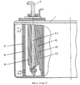
- the switching on and off of the electronic switch (16) and herewith the switching on and off of the electrical tubular heating elements (13), (14) and (15) is regulated by the temperature sensor (20). which is installed in the heating chamber (1.1) in the fuel tank (1), which can be seen in FIG. 2.
- Fig. 2 shows the heating chamber (1.1), inserted vertically into the fuel tank (1), consisting of the chamber housing (17) and thermal insulation (18), with suction hole (17.2) on the lower part and with ventilation hole (17.1) on the upper part Part of the housing (17).
- the suction pipe (6.1) and the electric tubular heating element (15) are mounted;
- the tubular heating element (15) runs along the entire length of the intake manifold (6.1) and is spirally rotated around the intake manifold mouth (6.1).
- the return line (11), suction line (23) for heating the interior of the motor vehicle and the temperature sensors ( 20) installed.
- the signal from the temperature sensor (20), which switches on the electronic switch (16), is shown in FIG. 1 Among other things, the electric tubular heating element (15) in the heating chamber (1.1) is switched on and heats the fuel that is in it. Fuel heated in this way flows together with the heated air through the vent hole (17.1) into a part of the fuel tank (1) on the heating chamber (1.1).
- Fig.3 shows the prefilter (4) on the fuel pump (3), which can be seen from Fig.1, consisting of the filter housing (3.1), in which the electric tubular heating element (13) is inserted from the bottom, which on the The bottom of the filter housing (3.1) is attached.
- the spring (22) is attached to the electrical tubular heating element (13) and the filter (4.1) to the spring (22).
- the filter housing (5.1) on the main filter (5) can be seen in FIG. 4, in which the underside is the electrical tubular heating element (14) which is attached to the bottom of the filter housing (5.1). On the electric tubular heating element (l4 ) the filter (21) is attached.
- the fuel heating device is used for fuel heating, primarily in winter when the outside air temperature drops below -15 ° C and when the fuel, especially with a filtration of -8 ° C in the fuel tank (1), in the lines (6), (8) and (8.1), in the prefilter (4) on the fuel pump (3) and on the main filter (5) freezes, the lines (6), (8) and (8.1) spieving the filters in the pre-filter (4) and in the main filter (5) are blocked by paraffin deposits, which also applies to the fuel in the fuel tank (1).
- the electronic switch (16) Before the engine is ignited, the electronic switch (16) is switched on, which is connected to an electrical battery on one side, but from the other side the electrical installation (16.1) is connected to the electronic switch (16), which the electrical Pipe heating elements (13), (14) and (15) are switched on, which, with the heating of the freezed fuel in the heating chamber (1.1) in the fuel tank (1), in the pre-filter (4) on the backing pump (3) and in the main filter (5) begin, whereby the paraffin melts in the fuel.
- the fuel in the heating chamber (1.1) in the fuel tank (1) is heated to the temperature of 0 ° C on the bottom of the heating chamber (1.1) after approx. 10 minutes, which allows the fuel to be sucked into the intake manifold (6.1) while the fuel in the central part of the heating chamber (1.1) is heated to 80 ° C, at the starting temperature of the fuel of -25 ° C. Because of the same heating effect in the prefilter (4) on the fuel pump (3) and in the main filter (5) with two Electric tubular heating elements (13) and (14) and because of the insulation effect on the lines (6), (8) and (8.1), the fuel can be fed unhindered from the fuel tank (l) into the high pressure pump (2), with ignition and Operation of the engine are enabled.
- the heated fuel flows back from the main filter (5) and through the return line (11) with built-in pressure valve (12) into the heating chamber (1.1), the total amount of fuel in the fuel tank older (1) is heated.
- the fuel in the fuel tank (1) is heated to -1 ° C after two minutes after the engine ignition (petroleum D2 with filtration of -8 ° C), the electrical tubular heating elements (15), (13) and (14) following a signal of the temperature sensor (20) in the heating chamber (1.1) can be switched off (by switch 16), which creates conditions for sucking the fuel out of the fuel tank (1), which is further heated by the heated fuel which flows into the fuel tank (1) flows back.
- the electric tubular heating elements (15), (13) and (14) are automatically switched on by the electronic switch (16) when the temperature sensor (20) in the heating chamber (1.1) registers a temperature drop in the fuel below -5 ° C.
- thermosphonic effect occurs, which causes an effective mixing of the heated and cold fuel, thereby a constant temperature of the fuel in the fuel tank (1) is reached, which is necessary for an undisturbed engine operation.
- the suction line (23) for heating the cab is mounted in the heating chamber (1.1) in the fuel tank (1), which at the same time enables the cab to be heated, whereby the separate motor or an additional electric tubular heating element for heating the interior of the vehicle is out of the question, or at all is not required.
- the heating chamber (1.1) in the fuel tank (1) only the amount of fuel consumed is heated during engine operation and not the entire amount of the pumped.
Landscapes
- Engineering & Computer Science (AREA)
- Chemical & Material Sciences (AREA)
- Combustion & Propulsion (AREA)
- Mechanical Engineering (AREA)
- General Engineering & Computer Science (AREA)
- Life Sciences & Earth Sciences (AREA)
- Sustainable Development (AREA)
- Sustainable Energy (AREA)
- Transportation (AREA)
- Cooling, Air Intake And Gas Exhaust, And Fuel Tank Arrangements In Propulsion Units (AREA)
Claims (11)
- Dispositif de chauffage de carburant pour des moteurs à combustion interne, en particulier pour un carburant diesel, notamment pour des moteurs diesel d'un système, dans lequel un réservoir, un préfiltre et un filtre principal sont chauffés électriquement d'une manière commandée par thermostat, caractérisé en ce qu'il est prévu une chambre de chauffage (1.1) insérée verticalement à l'intérieur d'un réservoir de carburant (1); la chambre de chauffage est fixée à la partie supérieure du boîtier du réservoir de carburant (1) et s'étend jusqu'à la base du récipient, et au centre de la chambre de chauffage est installé verticalement un tube d'aspiration (6.1), qui s'étend jusqu'au bord inférieur d'un boîtier (17) de la chambre et dont l'embouchure d'admission est découpée obliquement sous un certain angle, tandis que sur le tube d'aspiration (6.1) est monté verticalement un élément de chauffage (15), qui est enroulé en spirale au niveau de l'embouchure du tube d'aspiration (6.1), et que dans la chambre de chauffage (1.1) est prévue une canalisation de retour (11), et dans la chambre de chauffage (1.1) est disposée une canalisation de chauffage (23) servant à chauffer l'intérieur du véhicule, et qu'un élément de chauffage électrique tubulaire (13) est monté à l'intérieur et sur le fond d'un boîtier (3.1) du préfiltre (4) d'une pompe amont (3).
- Dispositif de chauffage de carburant selon la revendication 1, caractérisé en ce qu'un capteur de température (20) est monté verticalement contre la paroi du boîtier (17) de la chambre.
- Dispositif de chauffage de carburant selon l'une des revendications précédentes, caractérisé en ce qu'un trou de désaération (17.1) est prévu dans la partie supérieure de la chambre de chauffage (1,1), dans le boîtier (17).
- Dispositif de chauffage de carburant selon l'une des revendications précédentes, caractérisé en ce qu'un trou d'aspiration (17.2) est prévu dans le boîtier (17), dans la partie inférieure de la chambre de chauffage (1.1).
- Dispositif de chauffage de carburant selon la revendication 1, caractérisé en ce que l'élément de chauffage électrique tubulaire (13) est agencé selon une disposition en spirale.
- Dispositif de chauffage de carburant selon la revendication 1, caractérisé en ce qu'un élément de chauffage électrique tubulaire (14) est disposé à l'intérieur sur le fond du boîtier (5.1) du filtre principal (5).
- Dispositif de chauffage de carburant selon les revendications 1 et 6, caractérisé en ce que l'élément de chauffage électrique (14) est agencé avec une disposition en spirale.
- Dispositif de chauffage de carburant selon la revendication 1, caractérisé en ce que la canalisation d'aspiration (6) située entre le réservoir de carburant (1) et la pompe amont (3), et la canalisation de pression (8) située entre la pompe amont (3) et le filtre principal (5) sont isolées thermiquement.
- Dispositif de chauffage de carburant selon la revendication 5 ou 6, caractérisé en ce que les éléments chauffants électriques tubulaires (13,14,15) sont reliés au conducteur électrique (16.1) et à un interrupteur électronique (16).
- Dispositif de chauffage de carburant selon les revendications 1, 2 et 9, caractérisé en ce que le capteur de température (20) est relié à l'interrupteur électronique (16).
- Dispositif de chauffage de carburant selon les revendications 1 et 2, caractérisé en ce que la surface intérieure de la chambre de chauffage (1.1) est équipée d'une isolation thermique (18).
Priority Applications (2)
| Application Number | Priority Date | Filing Date | Title |
|---|---|---|---|
| AT92106966T ATE140061T1 (de) | 1992-04-23 | 1992-04-23 | Kraftstoffheizeinrichtung |
| DE59206706T DE59206706D1 (de) | 1992-04-23 | 1992-04-23 | Kraftstoffheizeinrichtung |
Applications Claiming Priority (1)
| Application Number | Priority Date | Filing Date | Title |
|---|---|---|---|
| HU913039A HU913039D0 (en) | 1991-09-23 | 1991-09-23 | Fuel pre-heater |
Publications (2)
| Publication Number | Publication Date |
|---|---|
| EP0566767A1 EP0566767A1 (fr) | 1993-10-27 |
| EP0566767B1 true EP0566767B1 (fr) | 1996-07-03 |
Family
ID=10962240
Family Applications (1)
| Application Number | Title | Priority Date | Filing Date |
|---|---|---|---|
| EP92106966A Expired - Lifetime EP0566767B1 (fr) | 1991-09-23 | 1992-04-23 | Installation de chauffage de carburant |
Country Status (2)
| Country | Link |
|---|---|
| EP (1) | EP0566767B1 (fr) |
| HU (1) | HU913039D0 (fr) |
Families Citing this family (7)
| Publication number | Priority date | Publication date | Assignee | Title |
|---|---|---|---|---|
| CN1302939C (zh) * | 2003-02-24 | 2007-03-07 | 菏泽创新风险投资有限公司 | 柴油车智能控温供燃油系统 |
| SE0400242L (sv) * | 2004-02-06 | 2005-06-07 | Scania Cv Abp | Ureatank för ett motorfordon |
| DE102005036430B4 (de) * | 2005-08-03 | 2011-05-05 | Eichenauer Heizelemente Gmbh & Co. Kg | Tankheizung |
| DE102005037201A1 (de) * | 2005-08-06 | 2007-02-22 | Eichenauer Heizelemente Gmbh & Co. Kg | Heizsystem |
| DE102009035272B4 (de) * | 2009-07-30 | 2013-05-23 | Elkamet Kunststofftechnik Gmbh | Heizbarer Flüssigkeitsbehälter mit adaptierbarem Heizelement und Verfahren zu seiner Herstellung |
| JP2018122682A (ja) * | 2017-01-31 | 2018-08-09 | ホクシン産業株式会社 | 燃料油移送装置 |
| CN107588825A (zh) * | 2017-09-15 | 2018-01-16 | 浙江车路科技有限公司 | 一种汽车油量测控仪 |
Citations (1)
| Publication number | Priority date | Publication date | Assignee | Title |
|---|---|---|---|---|
| DE3404817A1 (de) * | 1983-05-27 | 1984-11-29 | ÖMV AG, Wien | Einrichtung zur foerderung von kraftstoff |
Family Cites Families (5)
| Publication number | Priority date | Publication date | Assignee | Title |
|---|---|---|---|---|
| US3768730A (en) * | 1971-04-29 | 1973-10-30 | Int Research & Dev Co Ltd | Fuel pre-heater |
| DE3120960C2 (de) * | 1981-05-26 | 1984-08-09 | ÖMV AG, Wien | Einrichtung zur Förderung von Kraftstoff |
| EP0086602A1 (fr) * | 1982-02-05 | 1983-08-24 | Nigel Carle-Hay | Dispositif pour le réglage de la température du carburant pour un moteur de véhicule ou similaire |
| DE3510728A1 (de) * | 1985-01-24 | 1986-01-02 | Mehmet 8051 Nandlstadt Bursalioglu | Kaelteschutz fuer dieselkraftstoff in motoren |
| DE8523335U1 (de) * | 1985-08-14 | 1985-11-07 | Weber, Arno, 2300 Kiel | Thermotank mit Tankeinsatz und Kraftstoffilter |
-
1991
- 1991-09-23 HU HU913039A patent/HU913039D0/hu unknown
-
1992
- 1992-04-23 EP EP92106966A patent/EP0566767B1/fr not_active Expired - Lifetime
Patent Citations (1)
| Publication number | Priority date | Publication date | Assignee | Title |
|---|---|---|---|---|
| DE3404817A1 (de) * | 1983-05-27 | 1984-11-29 | ÖMV AG, Wien | Einrichtung zur foerderung von kraftstoff |
Also Published As
| Publication number | Publication date |
|---|---|
| EP0566767A1 (fr) | 1993-10-27 |
| HU62983A (fr) | 1993-06-28 |
| HU913039D0 (en) | 1992-01-28 |
Similar Documents
| Publication | Publication Date | Title |
|---|---|---|
| DE2715587C2 (de) | Kraftstoffversorgungseinrichtung für Brennkraftmaschinen | |
| DE3201149A1 (de) | Vorrichtung zum energiesparenden erwaermen eines treibstoffes in der treibstoffversorgung fuer eine brennkraftmaschine | |
| EP0305854A2 (fr) | Dispositif d'échauffement de gazole ou de mazout pour un moteur ou un brûleur | |
| DE69722941T2 (de) | Einspritzvorrichtung | |
| DE3034730A1 (de) | Verfahren zur aufloesung bzw. zur verhinderung von bei tiefer temperatur entstehenden ausscheidungen in einer fluessigkeit, insbesondere in einem treibstoff, und anordnung zur durchfuehrung des verfahrens | |
| DE19502082A1 (de) | Fahrzeugheizgerät | |
| DE69314592T2 (de) | Kraftstoffversorgungssystem für Brennkraftmaschine | |
| EP0566767B1 (fr) | Installation de chauffage de carburant | |
| DE2262030A1 (de) | Vorrichtung zur kraftstoffvorwaermung fuer verbrennungsmotoren, insbesondere dieselmotoren | |
| EP1144837B1 (fr) | Pompe d'alimentation en carburant pour un vehicule automobile et systeme d'alimentation en carburant equipe d'une telle pompe | |
| DE3120960C2 (de) | Einrichtung zur Förderung von Kraftstoff | |
| DE2602287A1 (de) | Verfahren zum verbrennen eines brennstoffgemisches | |
| DE102020131689A1 (de) | Kraftstoffheizanordnung | |
| EP0231298A1 (fr) | Dispositif de prechauffage de carburant diesel | |
| DE19631981A1 (de) | Anordnung und Verfahren zur Kühlung eines geschlossenen Kraftstoffversorgungskreislaufes eines Dieselaggregats | |
| DE3539721A1 (de) | Verfahren und vorrichtung zum vorerwaermen und zur verhinderung des ausflockens von dieselkraftstoff in kraftstoffiltern | |
| DE2416803A1 (de) | Elektronisch gesteuerte benzin-einspritzanlage | |
| DE3741281A1 (de) | Dieselheizer | |
| EP0319597A1 (fr) | Dispositif pour l'amélioration du fonctionnement à froid des moteurs diesel | |
| DE3931391C1 (fr) | ||
| DE3537566C1 (de) | Elektrische Heizvorrichtung zum Vorwärmen des Kraftstoffs von Brennkraftmaschinen, insbesondere Dieselmotoren | |
| DE3511781A1 (de) | Vorrichtung zum erwaermen von kraftstoff in einem kraftstoffsystem einer wassergekuehlten kraftfahrzeug-brennkraftmaschine | |
| DE3118422A1 (de) | Einrichtung zur kraftstoffaufbereitung | |
| DE19527256A1 (de) | Einrichtung zur Vorwärmung von Dieselbrennstoff für Heizgeräte in mobilen Einheiten | |
| DE3504629A1 (de) | Oxi-izotherme ernaehrungsanlage fuer autodieselmotore |
Legal Events
| Date | Code | Title | Description |
|---|---|---|---|
| PUAI | Public reference made under article 153(3) epc to a published international application that has entered the european phase |
Free format text: ORIGINAL CODE: 0009012 |
|
| AK | Designated contracting states |
Kind code of ref document: A1 Designated state(s): AT DE FR IT SE |
|
| K1C3 | Correction of patent application (complete document) published |
Effective date: 19931027 |
|
| 17P | Request for examination filed |
Effective date: 19940125 |
|
| 17Q | First examination report despatched |
Effective date: 19941005 |
|
| GRAH | Despatch of communication of intention to grant a patent |
Free format text: ORIGINAL CODE: EPIDOS IGRA |
|
| GRAA | (expected) grant |
Free format text: ORIGINAL CODE: 0009210 |
|
| AK | Designated contracting states |
Kind code of ref document: B1 Designated state(s): AT DE FR IT SE |
|
| REF | Corresponds to: |
Ref document number: 140061 Country of ref document: AT Date of ref document: 19960715 Kind code of ref document: T |
|
| REF | Corresponds to: |
Ref document number: 59206706 Country of ref document: DE Date of ref document: 19960808 |
|
| ITF | It: translation for a ep patent filed | ||
| ET | Fr: translation filed | ||
| PLBE | No opposition filed within time limit |
Free format text: ORIGINAL CODE: 0009261 |
|
| STAA | Information on the status of an ep patent application or granted ep patent |
Free format text: STATUS: NO OPPOSITION FILED WITHIN TIME LIMIT |
|
| 26N | No opposition filed | ||
| PGFP | Annual fee paid to national office [announced via postgrant information from national office to epo] |
Ref country code: FR Payment date: 19990224 Year of fee payment: 8 |
|
| PGFP | Annual fee paid to national office [announced via postgrant information from national office to epo] |
Ref country code: SE Payment date: 19990304 Year of fee payment: 8 |
|
| PGFP | Annual fee paid to national office [announced via postgrant information from national office to epo] |
Ref country code: DE Payment date: 19990430 Year of fee payment: 8 |
|
| PG25 | Lapsed in a contracting state [announced via postgrant information from national office to epo] |
Ref country code: SE Free format text: LAPSE BECAUSE OF NON-PAYMENT OF DUE FEES Effective date: 20000424 |
|
| PGFP | Annual fee paid to national office [announced via postgrant information from national office to epo] |
Ref country code: AT Payment date: 20001031 Year of fee payment: 9 |
|
| EUG | Se: european patent has lapsed |
Ref document number: 92106966.2 |
|
| PG25 | Lapsed in a contracting state [announced via postgrant information from national office to epo] |
Ref country code: FR Free format text: LAPSE BECAUSE OF NON-PAYMENT OF DUE FEES Effective date: 20001229 |
|
| PG25 | Lapsed in a contracting state [announced via postgrant information from national office to epo] |
Ref country code: DE Free format text: LAPSE BECAUSE OF NON-PAYMENT OF DUE FEES Effective date: 20010201 |
|
| REG | Reference to a national code |
Ref country code: FR Ref legal event code: ST |
|
| PG25 | Lapsed in a contracting state [announced via postgrant information from national office to epo] |
Ref country code: AT Free format text: LAPSE BECAUSE OF NON-PAYMENT OF DUE FEES Effective date: 20010423 |
|
| PG25 | Lapsed in a contracting state [announced via postgrant information from national office to epo] |
Ref country code: IT Free format text: LAPSE BECAUSE OF NON-PAYMENT OF DUE FEES;WARNING: LAPSES OF ITALIAN PATENTS WITH EFFECTIVE DATE BEFORE 2007 MAY HAVE OCCURRED AT ANY TIME BEFORE 2007. THE CORRECT EFFECTIVE DATE MAY BE DIFFERENT FROM THE ONE RECORDED. Effective date: 20050423 |