EP0565886B1 - Industrieschornstein mit Säureschutzeinrichtung - Google Patents
Industrieschornstein mit Säureschutzeinrichtung Download PDFInfo
- Publication number
- EP0565886B1 EP0565886B1 EP93104312A EP93104312A EP0565886B1 EP 0565886 B1 EP0565886 B1 EP 0565886B1 EP 93104312 A EP93104312 A EP 93104312A EP 93104312 A EP93104312 A EP 93104312A EP 0565886 B1 EP0565886 B1 EP 0565886B1
- Authority
- EP
- European Patent Office
- Prior art keywords
- chimney
- plates
- industrial
- protection device
- air guidance
- Prior art date
- Legal status (The legal status is an assumption and is not a legal conclusion. Google has not performed a legal analysis and makes no representation as to the accuracy of the status listed.)
- Expired - Lifetime
Links
- 239000002253 acid Substances 0.000 title claims description 22
- 239000003546 flue gas Substances 0.000 claims description 9
- 239000005336 safety glass Substances 0.000 claims description 6
- UGFAIRIUMAVXCW-UHFFFAOYSA-N Carbon monoxide Chemical compound [O+]#[C-] UGFAIRIUMAVXCW-UHFFFAOYSA-N 0.000 claims description 3
- 239000011521 glass Substances 0.000 claims description 3
- 239000002131 composite material Substances 0.000 claims 1
- QAOWNCQODCNURD-UHFFFAOYSA-N Sulfuric acid Chemical compound OS(O)(=O)=O QAOWNCQODCNURD-UHFFFAOYSA-N 0.000 description 2
- 230000007797 corrosion Effects 0.000 description 2
- 238000005260 corrosion Methods 0.000 description 2
- 241000446313 Lamella Species 0.000 description 1
- 238000010276 construction Methods 0.000 description 1
- 238000012423 maintenance Methods 0.000 description 1
- 239000000463 material Substances 0.000 description 1
- 239000000779 smoke Substances 0.000 description 1
- 239000000126 substance Substances 0.000 description 1
- 150000003464 sulfur compounds Chemical class 0.000 description 1
Images

Classifications
-
- F—MECHANICAL ENGINEERING; LIGHTING; HEATING; WEAPONS; BLASTING
- F23—COMBUSTION APPARATUS; COMBUSTION PROCESSES
- F23J—REMOVAL OR TREATMENT OF COMBUSTION PRODUCTS OR COMBUSTION RESIDUES; FLUES
- F23J13/00—Fittings for chimneys or flues
-
- F—MECHANICAL ENGINEERING; LIGHTING; HEATING; WEAPONS; BLASTING
- F23—COMBUSTION APPARATUS; COMBUSTION PROCESSES
- F23L—SUPPLYING AIR OR NON-COMBUSTIBLE LIQUIDS OR GASES TO COMBUSTION APPARATUS IN GENERAL ; VALVES OR DAMPERS SPECIALLY ADAPTED FOR CONTROLLING AIR SUPPLY OR DRAUGHT IN COMBUSTION APPARATUS; INDUCING DRAUGHT IN COMBUSTION APPARATUS; TOPS FOR CHIMNEYS OR VENTILATING SHAFTS; TERMINALS FOR FLUES
- F23L17/00—Inducing draught; Tops for chimneys or ventilating shafts; Terminals for flues
- F23L17/02—Tops for chimneys or ventilating shafts; Terminals for flues
Definitions
- the invention relates to an industrial chimney, the chimney mouth of which is arranged in a free-flow area above the ground, - with a chimney head, to which an acid protection device is attached, which is arranged at a distance from the chimney casing which forms an annular space, the acid protection device having a length in the chimney direction that is one Corresponds to several times the diameter of the chimney head.
- - Industrial chimney in the context of the invention designates chimneys of great height.
- Free flow area refers to an area of the atmospheric air space in which the air flow mainly follows the climatic potentials and is not influenced in terms of flow by structures close to the ground. The air flow that flows against such an industrial chimney creates a negative pressure on the leeward side for aerodynamic reasons.
- Flue gases withdrawing from the chimney mouth are drawn onto the wall of the chimney head in the form of a smoke plume on the leeward side.
- the flue gases are cooled below their dew point, so that aggressive substances such as sulfuric acid, sulfur compounds and the like can trigger severe corrosion.
- practice speaks of a down-wash effect.
- the acid protection device is designed as a nozzle casing which forms a closed nozzle casing around the chimney head in accordance with the annular space, the nozzle-shaped annular space thus formed at the bottom as well as in the area of the chimney mouth.
- the nozzle jacket has a jacket length that corresponds to a multiple of the diameter of the chimney head. Aerodynamic acid protection is thus achieved, the effect of which is largely determined by Bernoulli's relationships in aerodynamics. That has proven itself.
- the disturbing negative pressure causing the down-wash effect on the leeward side can be removed as long as the quotient of the inflow velocity of the air flow in the numerator and the exit velocity of the flue gases from the chimney mouth in the denominator is not too great.
- degree of obstruction denotes the ratio of the surface area of the nozzle jacket, in which the openings for the bypass channels are recessed, to the completely closed surface of this nozzle jacket, in percent, the completely closed nozzle jacket having a degree of obstruction of 100%.
- the invention has for its object to improve the acid protection in an industrial chimney of the construction described above, and to make it largely independent of the quotient of the inflow velocity of the air flow in the meter and the exit velocity of the flue gases from the chimney mouth.
- the invention teaches that the acid protection device has a plurality of air guide plates extending in the chimney direction, the width of which is smaller than corresponds to the outer radius of the chimney head, and that the air guide plates are arranged at a gap from one another.
- the air baffle plates have a width that is smaller than the radius of the chimney head.
- the air baffles are curved following the curvature of the chimney head and the gap distance is dimensioned such that the entire surface of all air baffles in relation to a corresponding acid protection device with a closed surface is considerably removed from 100%, thereby avoiding that the flue gas against the Chimney head (3) is pulled.
- they are also all regularly and equidistantly arranged around the chimney head.
- the invention is based on the knowledge that the aerodynamic acid protection described at the outset is considerably improved and on the quotient of the inflow speed of the air flow in the meter and the exit speed of the flue gases from the chimney outlet in
- the denominator can be made largely independent if one does not work with a nozzle jacket that is completely closed and whose function is therefore determined by Bernoulli's relationship. It is more advantageous, following the teaching of the invention, to additionally introduce kinetic energy from the inflowing air flow into the annular space, which is opened accordingly, so that the degree of obstruction defined at the outset is considerably removed from 100%. At the same time, corresponding outlet slots are created with the gap distances.
- a preferred embodiment of the invention is characterized in that the guide plates are designed in accordance with a degree of obstruction of 60% and are arranged equidistantly.
- the air baffle plates will be closed with the chimney outlet.
- the annular space of the acid protection device can be closed at the top and / or at the bottom.
- the acid protection device is preferably used where the industrial chimney has no cover.
- the air guide plates are designed as glass panes.
- they can be designed as safety glass panes.
- Such air baffles in turn are completely corrosion-resistant and require little maintenance. You can be set up so that they can withstand all stresses occurring without difficulty.
- a preferred embodiment is characterized in that the air baffle plates are designed as safety glass panes.
- the air baffles can be connected to the chimney head in different ways.
- the assembly means known from similar structures can be used (cf. DE 40 18 917 A1).
- the industrial chimney 1 shown in the figures has a chimney mouth 2 which is arranged sufficiently far above the ground in a free-flow area.
- the basic structure includes a chimney head 3, to which an acid protection device 4 is attached. This is arranged with an annular space-forming distance 5 from the chimney shell.
- the acid protection device 4 has a length in the chimney direction which corresponds to a multiple of the diameter of the chimney head 3.
- the acid protection device 4 has a plurality of air guide plates 6 extending in the chimney direction, the width of which is smaller than the outer diameter of the chimney head 3, the air guide plates 6 being arranged at a gap 7 from one another are.
- the air guide plates 6 have a width that is smaller than the radius of the chimney head 3.
- the air guide plates 6 are curved following the curvature of the chimney head 3.
- the air guide plates 6 are designed in accordance with a degree of obstruction of 60% and are arranged equidistantly.
- degree of blockage has been defined above. Particularly good results can be achieved if nine air baffle plates are arranged equidistantly.
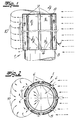
- Fig. 1 it can be seen that the air guide plates 6 terminate approximately with the chimney mouth 2.
- the annular space can be closed off at least at the upper end by an annular disk 8.
- the air guide plates 6 may be designed as glass panes, preferably made of safety glass and laminated safety glass.
Landscapes
- Engineering & Computer Science (AREA)
- Mechanical Engineering (AREA)
- General Engineering & Computer Science (AREA)
- Chemical & Material Sciences (AREA)
- Combustion & Propulsion (AREA)
- Chimneys And Flues (AREA)
- Organic Low-Molecular-Weight Compounds And Preparation Thereof (AREA)
Description
- Die Erfindung betrifft einen Industrieschornstein, dessen Schornsteinmündung in einem Freiströmungsbereich oberhalb des Erdbodens angeordnet ist, - mit einem Schornsteinkopf, an dem eine Säureschutzeinrichtung befestigt ist, die mit ringraumbildendem Abstand von dem Schornsteinmantel angeordnet ist, wobei die Säureschutzeinrichtung in Schornsteinrichtung eine Länge aufweist, die einem Mehrfachen des Durchmessers des Schornsteinkopfes entspricht. - Industrieschornstein bezeichnet im Rahmen der Erfindung Schornsteine großer Höhe. Freiströmungsbereich bezeichnet einen Bereich des atmosphärischen Luftraumes, in dem die Luftströmung hauptsächlich den klimatisch bedingten Potentialen folgt und durch erdbodennahe Bauwerke strömungsmäßig nicht störend beeinflußt ist. Die Luftströmung, die einen solchen Industrieschornstein anströmt, erzeugt aus aerodynamischen Gründen auf der Leeseite einen Unterdruck. Aus der Schornsteinmündung abziehende Rauchgase werden in Form einer Rauchfahne auf der Leeseite außen an die Wandung des Schornsteinkopfes herangezogen. Infolge der hier herrschenden niedrigen Temperaturen werden die Rauchgase unter ihren Taupunkt abgekühlt, so daß aggressive Stoffe, wie Schwefelsäure, Schwefelverbindungen und dergleichen eine starke Korrosion auslösen können. Die Praxis spricht insoweit von einem Down-wash-Effekt.
- Bei dem bekannten Industrieschornstein, von dem die Erfindung ausgeht (DE 40 18 917 A1), ist die Säureschutzeinrichtung als Düsenmantel ausgebildet, der um den Schornsteinkopf nach Maßgabe des Ringraumes einen geschlossenen Düsenmantel bildet, wobei der so gebildete düsenförmige Ringraum unten sowie im Bereich der Schornsteinmündung offen ist. Der Düsenmantel besitzt eine Mantellänge, die einem Mehrfachen des Durchmessers des Schornsteinkopfes entspricht. Man erreicht so einen aerodynamischen Säureschutz, der in seiner Wirkung weitgehend durch die Bernoulli'schen Beziehungen der Aerodynamik bestimmt ist. Das hat sich bewährt. Der störende, den Down-wash-Effekt bewirkende Unterdruck auf der Leeseite kann aufgehoben werden, solange der Quotient aus der Anströmgeschwindigkeit der Luftströmung im Zähler und der Austrittsgeschwindigkeit der Rauchgase aus der Schornsteinmündung im Nenner nicht zu groß ist. Zwar wird im Rahmen dieser bekannten Maßnahmen vorgeschlagen, in dem Düsenmantel einige Öffnungen vorzusehen, das ändert jedoch nichts an den vorstehend beschriebenen Verhältnissen, weil mit Hilfe der Öffnungen lediglich Bypasskanäle geschaffen werden sollen, der sogenannte Versperrungsgrad jedoch nichtsdestoweniger bei praktisch 100 % liegt. Versperrungsgrad bezeichnet das Verhältnis der Oberfläche des Düsenmantels, in dem die Öffnungen für die Bypaßkanäle ausgespart sind, zu der vollständig geschlossenen Oberfläche dieses Düsenmantels in Prozent, wobei der vollständig geschlossene Düsenmantel den Versperrungsgrad von 100 % aufweist.
- Der Erfindung liegt die Aufgabe zugrunde, bei einem Industrieschornstein des eingangs beschriebenen Aufbaus den Säureschutz zu verbessern, und zwar weitgehend unabhängig zu machen von dem Quotienten aus der Anströmgeschwindigkeit der Luftströmung im Zähler und der Austrittsgeschwindigkeit der Rauchgase aus der Schornsteinmündung.
- Zur Lösung dieser Aufgabe lehrt die Erfindung, daß die Säureschutzeinrichtung eine Mehrzahl von in Schornsteinrichtung erstreckten Luftleitplatten aufweist, deren Breite kleiner ist, als es dem äußeren Radius des Schornsteinkopfes entspricht, und daß die Luftleitplatten mit Spaltabstand voneinander angeordnet sind. Die Luftleitplatten weisen dabei eine Breite auf, die kleiner ist, als es dem Radius des Schornsteinkopfes entspricht. Nach der Erfindung sind die Luftleitplatten der Krümmung des Schornsteinkopfes folgend gekrümmt und der Spaltabstand wird so bemessen, daß die gesamte Oberfläche aller Luftleitplatten im Verhältnis zu einer entsprechenden Säureschutzeinrichtung mit geschlossener Oberfläche beträchtlich von 100% entfernt liegt, wodurch vermieden wird, daß das Rauchgas gegen den Schornsteinkopf (3) gezogen wird. Nach bevorzugten Ausfuhrungsform sind sie fernerhin regelmäßig alle gleich breit und äquidistant um den Schornsteinkopf angeordnet. Bei Schornsteinaufsätzen für Hauskamine ist es bekannt (DE-PS 804 449), mit einem Rohr zu arbeiten, welches auf die Schornsteinmündung aufgesetzt wird. Dieses Rohr besitzt in Längsrichtung verlaufende Schlitze und mit Abstand vor den Schlitzen Luftleiteinrichtungen. Bei solchen Schornsteinen für Hauskamine ist es auch bekannt (DE 31 22 337 (2)), auf den Schornstein gleichsam einen Käfig aufzusetzen, der aus in horizontaler Richtung umlaufenden Tragringen und darauf aufgesetzten, nach außen konvexen Profillamellen besteht. Die Probleme um den Säureschutz bei Industriekaminen sind durch diese bekannten Maßnahmen nicht beeinflußt worden. In beiden Fällen wird ein Ringraum um den Strömungskanal für die Rauchgase nicht gebildet.
- Die Erfindung geht von der Erkenntnis aus, daß der eingangs beschriebene aerodynamische Säureschutz beachtlich verbessert werden und von dem Quotienten aus der Anströmgeschwindigkeit der Luftströmung im Zähler und der Austrittsgeschwindigkeit der Rauchgase aus der Schornsteinmündung im Nenner weitgehend unabhängig gemacht werden kann, wenn nicht mit einem Düsenmantel gearbeitet wird, der vollständig geschlossen ist und dessen Funktion daher durch die Bernoulli'sche Beziehung bestimmt ist. Vorteilhafter ist es, der Lehre der Erfindung folgend, zusätzlich Bewegungsenergie aus der anströmenden Luftströmung in den Ringraum einzuführen, der dazu entsprechend geöffnet ist, so daß der eingangs definierte Versperrungsgrad beachtlich von 100 % entfernt ist. Gleichzeitig entstehen mit den Spaltabständen entsprechende Austrittsschlitze. Eine bevorzugte Ausführungsform der Erfindung ist dadurch gekennzeichnet, daß die Leitplatten nach Maßgabe eines Versperrungsgrades von 60 % ausgebildet und äquidistant angeordnet sind.
- Im einzelnen bestehen im Rahmen der Erfindung mehrere Möglichkeiten der weiteren Ausbildung und Gestaltung. So wird man die Luftleitplatten etwa mit der Schornsteinmündung abschließen lassen. Der Ringraum der Säureschutzeinrichtung kann oben und/oder unten geschlossen sein. Die Säureschutzeinrichtung wird im übigen vorzugsweise dort eingesetzt, wo der Industrieschornstein keine Abdeckung aufweist.
- In werkstoffmäßiger Hinsicht bestehen im Rahmen der Erfindung mehrere Möglichkeiten. Besondere Vorteile erreicht man dadurch, daß die Luftleitplatten als Glasscheiben ausgeführt sind. Sie können insbesondere als Sicherheitsglasscheiben ausgeführt sein. Solche Luftleitplatten sind ihrerseits vollkommen korrosionsfest und wartungsarm. Sie können so eingerichtet werden, daß sie alle auftretenden Beanspruchungen ohne Schwierigkeiten aufnehmen. Insoweit ist eine bevorzugte Ausführungsform dadurch gekennzeichnet, daß die Luftleitplatten als Sicherheitsglasscheiben ausgeführt sind. Der Anschluß der Luftleitplatten an den Schornsteinkopf kann auf verschiedene Weise erfolgen. Insbesondere können die Montagemittel eingesetzt werden, die bei ähnlichen Bauwerken bekannt sind (vgl. DE 40 18 917 A1).
- Im folgenden wird die Erfindung anhand einer lediglich ein Ausführungsbeispiel darstellenden Zeichnung ausführlicher erläutert. Es zeigen in schematischer Darstellung
- Fig. 1
- die Seitenansicht eines erfindungsgemäßen Industrieschornsteines mit Säureschutzeinrichtung, ausschnittsweise,
- Fig. 2
- einen Horizontalschnitt durch den Gegenstand der Fig. 1 und
- Fig. 3
- einen Vertikalschnitt durch den Gegenstand nach Fig. 1.
- Der in den Figuren dargestellte Industrieschornstein 1 besitzt eine Schornsteinmündung 2, die in einem Freiströmungsbereich ausreichend weit oberhalb des Erdbodens angeordnet ist. Zum grundsätzlichen Aufbau gehören ein Schornsteinkopf 3, an dem eine Säureschutzeinrichtung 4 befestigt ist. Diese ist mit ringraumbildendem Abstand 5 vom Schornsteinmantel angeordnet. Die Säureschutzeinrichtung 4 besitzt in Schornsteinrichtung eine Länge, die einem Mehrfachen des Durchmessers des Schornsteinkopfes 3 entspricht.
- Aus einer vergleichenden Betrachtung der Fig. 1 bis 3 entnimmt man, daß die Säureschutzeinrichtung 4 eine Mehrzahl von in Schornsteinrichtung erstreckten Luftleitplatten 6 aufweist, deren Breite kleiner ist, als es dem Außendurchmesser des Schornsteinkopfes 3 entspricht, wobei die Luftleitplatten 6 mit Spaltabstand 7 voneinander angeordnet sind. Die Luftleitplatten 6 besitzen eine Breite, die kleiner ist als der Radius des Schornsteinkopfes 3. Die Luftleitplatten 6 sind der Krümmung des Schornsteinkopfes 3 folgend gekrümmt.
- Im Ausführungsbeispiel und nach bevorzugter Ausführungsform der Erfindung sind die Luftleitplatten 6 nach Maßgabe eines Versperrungsgrades von 60 % ausgebildet und äquidistant angeordnet. Der Begriff des Versperrungsgrades ist oben definiert worden. Besonders gute Ergebnisse erzielt man, wenn neun Luftleitplatten äquidistant angeordnet werden.
- In der Fig. 1 erkennt man, daß die Luftleitplatten 6 etwa mit der Schornsteinmündung 2 abschließen. Der Ringraum kann zumindest am oberen Ende durch eine Ringscheibe 8 abgeschlossen sein.
- Die Luftleitplatten 6 mögen als Glasscheiben ausgeführt sein, vorzugsweise aus Sicherheitsglas und Verbundsicherheitsglas.
- In den Figuren 1 und 2 wurde angedeutet, wie die Luftströmung den Schornsteinkopf 3 mit der Säureschutzeinrichtung 4 anströmt. Pfeile 9 in den Fig. 1 und 2 machen deutlich, welche aerodynamischen Strömungsbilder erreicht werden. Zugleich verdeutlichen die Pfeile 10, daß das Rauchgas auf der Leeseite des anströmenden Windes nicht gegen den Schornsteinkopf 3 gezogen werden kann.
Claims (10)
- Industrieschornstein, dessen Schornsteinmündung (2) in einem Freiströmungsbereich oberhalb des Erdbodens angeordnet ist, - mit
einem Schornsteinkopf (3), an dem eine Säureschutzeinrichtung (4) befestigt ist, die mit ringraumbildendem Abstand (5) von dem Schornsteinmantel angeordnet ist,
wobei die Säureschutzeinrichtung (4) in Schornsteinrichtung eine Länge aufweist, die einem Mehrfachen des Durchmessers des Schornsteinkopfes (3) entspricht, dadurch gekennzeichnet, daß die Säureschutzeinrichtung (4) eine Mehrzahl von in Schornsteinrichtung erstreckten Luftleitplatten (6) aufweist, die der Krümmung des Schornsteinkopfes (3) folgend gekrümmt sind und deren Breite kleiner ist, als es dem äußeren Radius des Schornsteinkopfes (3) entspricht, und daß die Luftleitplatten (6) mit Spaltabstand (7) voneinander angeordnet sind, wobei der Spaltabstand (7) so bemessen ist, daß die gesamte Oberfläche aller Luftleitplatten (6) im Verhältnis zu einer entsprechenden Säureschutzeinrichtung (4) mit geschlossener Oberfläche beträchtlich von 100% entfernt liegt wodurch wermieden wird, daß das Rauchgas gegen den Schornsteinkopf (3) gezogen wird. - Industrieschornstein nach Anspruch 1, dadurch gekennzeichnet, daß die Luftleitplatten (6) nach Maßgabe eines Versperrungsgrades von 60 % ausgebildet und äquidistant angeordnet sind.
- Industrieschornstein nach einem der Ansprüche 1 oder 2, dadurch gekennzeichnet, daß die neun Luftleitplatten (6) äquidistant angeordnet sind.
- Industrieschornstein nach einem der Ansprüche 1 bis 3, dadurch gekennzeichnet, daß die Luftleitplatten (6) etwa mit der Schornsteinmündung (2) abschließen.
- Industrieschornstein nach einem der Ansprüche 1 bis 4, dadurch gekennzeichnet, daß der Ringraum (5) der Säureschutzeinrichtung (4) zumindest am oberen Rand abgeschlossen ist.
- Industrieschornstein nach einem der Ansprüche 1 bis 5, dadurch gekennzeichnet, daß die Luftleitplatten (6) als Glasscheiben ausgeführt sind.
- Industrieschornstein nach einem der Ansprüche 1 bis 6, dadurch gekennzeichnet, daß die Luftleitplatten (6) als Sicherheitsglasscheiben ausgeführt sind.
- Industrieschornstein nach einem der Ansprüche 1 bis 7, dadurch gekennzeichnet, daß die Luftleitplatten (6) als Verbundsicherheitsglasscheiben ausgeführt sind.
- Industrieschornstein nach einem der Ansprüche 1 bis 8, dadurch gekennzeichnet, daß an die Luftleitplatten (6) oberseitig und/oder unterseitig Abdeckplatten angeschlossen sind, die mit radialer Verjüngung zum Schornsteinmantel geführt und an diesen angeschlossen sind.
- Industrieschornstein nach Anspruch 9, dadurch gekennzeichnet, daß die Abdeckplatten oberseitig und/oder unterseitig Strömungsöffnungen aufweisen.
Applications Claiming Priority (2)
| Application Number | Priority Date | Filing Date | Title |
|---|---|---|---|
| DE4211698A DE4211698A1 (de) | 1992-04-07 | 1992-04-07 | Industrieschornstein mit Säureschutzeinrichtung |
| DE4211698 | 1992-04-07 |
Publications (2)
| Publication Number | Publication Date |
|---|---|
| EP0565886A1 EP0565886A1 (de) | 1993-10-20 |
| EP0565886B1 true EP0565886B1 (de) | 1996-12-18 |
Family
ID=6456325
Family Applications (1)
| Application Number | Title | Priority Date | Filing Date |
|---|---|---|---|
| EP93104312A Expired - Lifetime EP0565886B1 (de) | 1992-04-07 | 1993-03-17 | Industrieschornstein mit Säureschutzeinrichtung |
Country Status (4)
| Country | Link |
|---|---|
| EP (1) | EP0565886B1 (de) |
| AT (1) | ATE146584T1 (de) |
| DE (2) | DE4211698A1 (de) |
| DK (1) | DK0565886T3 (de) |
Families Citing this family (1)
| Publication number | Priority date | Publication date | Assignee | Title |
|---|---|---|---|---|
| FR2792062B1 (fr) * | 1999-04-06 | 2001-12-21 | Cie Tech Des Petroles | Agencement pour la dissipation des fumees autour d'une cheminee et cheminee equipee d'un tel agencement |
Family Cites Families (4)
| Publication number | Priority date | Publication date | Assignee | Title |
|---|---|---|---|---|
| FR1193912A (de) * | 1959-11-05 | |||
| US2627219A (en) * | 1950-01-31 | 1953-02-03 | Air Devices Inc | Air exhauster |
| FR2227496A1 (en) * | 1973-04-27 | 1974-11-22 | Larroque Andre | Chimney cowl bolted to top of chimney - has concentric rings of vert. baffles below cover plate bolted in place |
| DE4018917A1 (de) * | 1990-06-13 | 1991-12-19 | Flachglas Consult Gmbh | Industrie-schornstein mit saeureschutzeinrichtung |
-
1992
- 1992-04-07 DE DE4211698A patent/DE4211698A1/de not_active Withdrawn
-
1993
- 1993-03-17 EP EP93104312A patent/EP0565886B1/de not_active Expired - Lifetime
- 1993-03-17 DE DE59304781T patent/DE59304781D1/de not_active Expired - Fee Related
- 1993-03-17 DK DK93104312.9T patent/DK0565886T3/da active
- 1993-03-17 AT AT93104312T patent/ATE146584T1/de active
Also Published As
| Publication number | Publication date |
|---|---|
| DE4211698A1 (de) | 1993-10-14 |
| DE59304781D1 (de) | 1997-01-30 |
| DK0565886T3 (da) | 1997-01-06 |
| EP0565886A1 (de) | 1993-10-20 |
| ATE146584T1 (de) | 1997-01-15 |
Similar Documents
| Publication | Publication Date | Title |
|---|---|---|
| EP3556452B1 (de) | Anlage zur absorption von einzelkomponenten in gasen | |
| EP0565886B1 (de) | Industrieschornstein mit Säureschutzeinrichtung | |
| EP0221941B1 (de) | Schornsteinaufsatz | |
| EP1550807A1 (de) | Verfahren und Vorrichtung zur Strömungsbeschleunigung einer Windenergie- oder Wasserstromanlage | |
| AT395064B (de) | Aufsatz fuer abgasleitungen | |
| DE2829592A1 (de) | Tropfenabscheider | |
| DE3127289C1 (de) | Einrichtung zur Impulsbelüftung von Tunnels | |
| DE2924963C2 (de) | Kaminkopf für Luft-Abgas-Schornsteine | |
| EP3293463A1 (de) | Schlitzauslass für luftschleiervorrichtungen | |
| DE1027833B (de) | Schornstein mit Abstroemplatte | |
| AT375455B (de) | Schornsteinaufsatz fuer zentralheizungsanlagen mit zerstaeubungsbrennern | |
| DE2461982B2 (de) | Kühlturm mit einer außen an der Krone angeordneten Wmdleitvorriehtung | |
| EP0461576A2 (de) | Industrie-Schornstein mit Säureschutzeinrichtung | |
| DE3010316C2 (de) | Kamin für industrielle Abgase | |
| DE3237216A1 (de) | Schornsteinaufsatz fuer zentralheizungsanlagen mit zerstaeubungsbrennern | |
| DE1260669B (de) | Schornsteinaufsatz | |
| DE2360264C3 (de) | Abgaskamin mit den Abgasstrom veränderbar drosselnder Vorrichtung | |
| DE85126C (de) | ||
| DE4302229A1 (de) | Rauchgasabströmkopf bzw. Vorrichtung als äußerer Abschluß eines Rauchgasrohrs sowie Zuschnitt für einen Rauchgasabströmkopf | |
| DE8312172U1 (de) | Kaminabdeckung | |
| DE1071728B (de) | ||
| DD280380A1 (de) | Ventilatorkuehlturm | |
| DE7808184U1 (de) | Schornsteinauf- bzw. einsatz | |
| EP0122413A1 (de) | Kaminhaube | |
| DE3222387A1 (de) | Abgaskanal, insbesondere mit eingebautem schalldaempfer aus mit mineralwolle gefuellten kulissen, sowie regenschutzvorrichtung hierfuer |
Legal Events
| Date | Code | Title | Description |
|---|---|---|---|
| PUAI | Public reference made under article 153(3) epc to a published international application that has entered the european phase |
Free format text: ORIGINAL CODE: 0009012 |
|
| AK | Designated contracting states |
Kind code of ref document: A1 Designated state(s): AT BE CH DE DK FR GB IT LI |
|
| 17P | Request for examination filed |
Effective date: 19940413 |
|
| 17Q | First examination report despatched |
Effective date: 19950703 |
|
| GRAG | Despatch of communication of intention to grant |
Free format text: ORIGINAL CODE: EPIDOS AGRA |
|
| GRAH | Despatch of communication of intention to grant a patent |
Free format text: ORIGINAL CODE: EPIDOS IGRA |
|
| GRAH | Despatch of communication of intention to grant a patent |
Free format text: ORIGINAL CODE: EPIDOS IGRA |
|
| GRAA | (expected) grant |
Free format text: ORIGINAL CODE: 0009210 |
|
| AK | Designated contracting states |
Kind code of ref document: B1 Designated state(s): AT BE CH DE DK FR GB IT LI |
|
| REF | Corresponds to: |
Ref document number: 146584 Country of ref document: AT Date of ref document: 19970115 Kind code of ref document: T |
|
| REG | Reference to a national code |
Ref country code: CH Ref legal event code: NV Representative=s name: KELLER & PARTNER PATENTANWAELTE AG |
|
| REG | Reference to a national code |
Ref country code: DK Ref legal event code: T3 |
|
| ITF | It: translation for a ep patent filed | ||
| REF | Corresponds to: |
Ref document number: 59304781 Country of ref document: DE Date of ref document: 19970130 |
|
| ET | Fr: translation filed | ||
| GBT | Gb: translation of ep patent filed (gb section 77(6)(a)/1977) |
Effective date: 19970125 |
|
| PGFP | Annual fee paid to national office [announced via postgrant information from national office to epo] |
Ref country code: GB Payment date: 19970228 Year of fee payment: 5 |
|
| PGFP | Annual fee paid to national office [announced via postgrant information from national office to epo] |
Ref country code: FR Payment date: 19970319 Year of fee payment: 5 |
|
| PGFP | Annual fee paid to national office [announced via postgrant information from national office to epo] |
Ref country code: DK Payment date: 19970321 Year of fee payment: 5 Ref country code: BE Payment date: 19970321 Year of fee payment: 5 Ref country code: AT Payment date: 19970321 Year of fee payment: 5 |
|
| PGFP | Annual fee paid to national office [announced via postgrant information from national office to epo] |
Ref country code: CH Payment date: 19970324 Year of fee payment: 5 |
|
| PLBE | No opposition filed within time limit |
Free format text: ORIGINAL CODE: 0009261 |
|
| STAA | Information on the status of an ep patent application or granted ep patent |
Free format text: STATUS: NO OPPOSITION FILED WITHIN TIME LIMIT |
|
| 26N | No opposition filed | ||
| PGFP | Annual fee paid to national office [announced via postgrant information from national office to epo] |
Ref country code: DE Payment date: 19971219 Year of fee payment: 6 |
|
| PG25 | Lapsed in a contracting state [announced via postgrant information from national office to epo] |
Ref country code: GB Free format text: LAPSE BECAUSE OF NON-PAYMENT OF DUE FEES Effective date: 19980317 Ref country code: AT Free format text: LAPSE BECAUSE OF NON-PAYMENT OF DUE FEES Effective date: 19980317 |
|
| PG25 | Lapsed in a contracting state [announced via postgrant information from national office to epo] |
Ref country code: LI Free format text: LAPSE BECAUSE OF NON-PAYMENT OF DUE FEES Effective date: 19980331 Ref country code: FR Free format text: THE PATENT HAS BEEN ANNULLED BY A DECISION OF A NATIONAL AUTHORITY Effective date: 19980331 Ref country code: DK Free format text: LAPSE BECAUSE OF NON-PAYMENT OF DUE FEES Effective date: 19980331 Ref country code: CH Free format text: LAPSE BECAUSE OF NON-PAYMENT OF DUE FEES Effective date: 19980331 Ref country code: BE Free format text: LAPSE BECAUSE OF NON-PAYMENT OF DUE FEES Effective date: 19980331 |
|
| BERE | Be: lapsed |
Owner name: FLACHGLAS CONSULT G.M.B.H. Effective date: 19980331 |
|
| GBPC | Gb: european patent ceased through non-payment of renewal fee |
Effective date: 19980317 |
|
| REG | Reference to a national code |
Ref country code: CH Ref legal event code: PL |
|
| REG | Reference to a national code |
Ref country code: FR Ref legal event code: ST |
|
| PG25 | Lapsed in a contracting state [announced via postgrant information from national office to epo] |
Ref country code: DE Free format text: LAPSE BECAUSE OF NON-PAYMENT OF DUE FEES Effective date: 20000101 |
|
| REG | Reference to a national code |
Ref country code: DK Ref legal event code: EBP |
|
| PG25 | Lapsed in a contracting state [announced via postgrant information from national office to epo] |
Ref country code: IT Free format text: LAPSE BECAUSE OF NON-PAYMENT OF DUE FEES;WARNING: LAPSES OF ITALIAN PATENTS WITH EFFECTIVE DATE BEFORE 2007 MAY HAVE OCCURRED AT ANY TIME BEFORE 2007. THE CORRECT EFFECTIVE DATE MAY BE DIFFERENT FROM THE ONE RECORDED. Effective date: 20050317 |