EP0559152A2 - Diagram drawing apparatus - Google Patents
Diagram drawing apparatus Download PDFInfo
- Publication number
- EP0559152A2 EP0559152A2 EP93103313A EP93103313A EP0559152A2 EP 0559152 A2 EP0559152 A2 EP 0559152A2 EP 93103313 A EP93103313 A EP 93103313A EP 93103313 A EP93103313 A EP 93103313A EP 0559152 A2 EP0559152 A2 EP 0559152A2
- Authority
- EP
- European Patent Office
- Prior art keywords
- line
- target
- diagram
- coordinates
- enlarged
- Prior art date
- Legal status (The legal status is an assumption and is not a legal conclusion. Google has not performed a legal analysis and makes no representation as to the accuracy of the status listed.)
- Withdrawn
Links
Images


Classifications
-
- G—PHYSICS
- G06—COMPUTING OR CALCULATING; COUNTING
- G06T—IMAGE DATA PROCESSING OR GENERATION, IN GENERAL
- G06T11/00—Two-dimensional [2D] image generation
- G06T11/20—Drawing from basic elements
- G06T11/26—Drawing of charts or graphs
Definitions
- the present invention relates to a diagram drawing apparatus for drawing a diagram including a straight line, a rectangle, a circle, an arc, etc. and, more particularly, to a diagram drawing apparatus capable of enlarging or reducing a figure without performing any operation of an operator for modifying other figures relating to the enlarged on reduced figure.
- a diagram drawing apparatus has recently been developed on the basis of a personal computer.
- a diagram such as a flowchart is prepared and edited by the diagram drawing apparatus, a specific figure has to be often enlarged or reduced.
- a target figure can be enlarged or reduced by editing, but the other figures relating to the target figure remain unchanged.
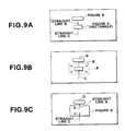
- FIG. 9A a diagram of the flowchart including a rectangle A, straight lines B and C whose ends are tangent to the rectangle A, and a figure D for a starting step, is prepared.
- the rectangle A is enlarged to a range indicated by a broken line A' as shown in Fig. 9B, none of the other figures B-D change. In other words, the straight lines B and C remain unchanged. Therefore, as shown in Fig. 9C, the end portions b and c of the straight lines B and C go inside the enlarged rectangle A'.
- a user has to perform an edit operation to delete the end portions b and c of the straight lines B and C going inside the enlarged rectangle A'. This edit operation is very troublesome and complicated.
- diagram data is read out from a diagram data memory section and displayed on a display section. If a target figure of the diagram data displayed on the display section is designated by a designating section, it is enlarged or reduced by an enlargement/reduction section.
- a retrieving section retrieves from the diagram data memory section line data denoting a line whose end is tangent to the target figure designated by the designating section, and a line end processor shortens or lengthens the line retrieved by the retrieving section so that the end of the line is made tangent to the target figure enlarged or reduced by the enlargement/ reduction section.
- the line is shortened.
- the line is lengthened.
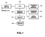
- Fig. 1 is a block diagram showing a circuit arrangement of a diagram drawing apparatus according to an embodiment of the present invention.
- an input device 11 of the diagram drawing apparatus includes a keyboard having function keys such as an execution key and a cursor moving key, and a mouse 11a for moving a mouse cursor to an arbitrary position. Operation signals of the keyboard and mouse are supplied to a CPU 12.
- the CPU 12 executes various processings such as input control processing and figure edit processing, based on programs stored in advance in a program memory 13.
- the program memory 13 is constituted by a ROM, a RAM, a magnetic disk apparatus, or the like.
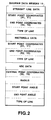
- a diagram data memory 14 stores a diagram (e.g., drawing of a flowchart) prepared by a user in diagram data form, as shown in Fig. 2.
- data of an unit figure such as a straight line, a rectangle, and an arc is stored, together with information of coordinates and size of the unit figure, and a type of the line of the unit figure.
- data of the straight line and the rectangle includes coordinates of a start point, those of an end point, a type of a line, etc.
- data of the arc includes central coordinates, a radius, angles of the start and end points, a type of the line, etc.
- a data memory 15 has a plurality of memories necessary for executing various processings.
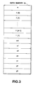
- Fig. 3 is a view showing a configuration of the data memory 15.
- memory areas of the data memory 15 are a memory area n for storing the number of figures, memory areas f[0] to f[n] for storing the position of figure data, a memory area cnt for designating the figure data, and memory areas x1 to x3 and y1 to y3 for storing the coordinates of ends of lines.
- a display memory 16 stores display data being displayed on a display device 18, as a dot pattern, and converts the diagram data stored in the diagram data memory 14 into figure image data and stores the figure image data.
- the display data stored in the display memory 16 is displayed on the display device 18 through a driver 17.
- the display device 18 is constituted by, for example, a CRT display device.
- FIG. 4 shows a figure edit display on which the enlargement processing is executed when a diagram of a flowchart is prepared.
- Fig. 4A shows the diagram of the flowchart displayed on the display device 18, the diagram being prepared by a user and stored in the diagram data memory 14.
- the diagram of the flowchart is formed of a figure A of a rectangle which represents a processing step, a straight line B whose one end contacts the upper side of the figure A, a straight line C whose one end is tangent to the lower side of the figure A, and a figure D for a starting step.
- keys of the input device 11 are operated to designate the enlargement processing, then a mouse of the input device 11 is operated to move a mouse cursor to the figure A on the display device, and a click operation is performed to designate the figure A as a target figure F0 for the enlargement processing. After that, the mouse cursor is moved to an intersection point of the diagonals of a rectangle indicated by the broken line to designate a size of the enlarged figure A' and perform a click operation.
- the enlargement processing is started.
- Fig. 5 shows a flowchart of the enlargement/reduction processing.
- the enlargement/reduction processing includes an enlargement processing and a reduction processing.
- step A1 a figure (a straight line, an arc, a free line, etc.) an end of which is tangent to the target figure F0 (figure A) is retrieved from diagram data stored in the diagram data memory 14.
- the straight lines B and C shown in Fig. 4A are retrieved from the memory 14, and the number "2" of the retrieved figures is stored in the memory area n of the data memory 15.
- Position data (coordinates of the start and end points, etc.) of the retrieved figures is stored in the memory areas f[0] to f[n-1] of the data memory 15.
- the memory area f[n) is a memory area designated by the data stored in the memory area n .
- step A2 "0" is written to the memory area cnt of the data memory 15 to initialize the apparatus.
- step A4 the coordinates of the end of a target line are adjusted or changed in accordance with the type of a figure (straight line, arc, free line, etc.) stored in the memory area f[cnt] designated by the information stored in the memory area cnt. More specifically, in this line end coordinates adjustment processing, when the target figure F0 (figure A) is enlarged or reduced to a specified position, the coordinates of the target line are changed with respect to the enlarged or reduced figure, with the result that the target line is shortened or elongated. In the enlargement processing, the coordinates of the end of the line going or projecting inside the enlarged target figure F0' are changed to delete a projected line portion in substance. In the reduction processing, the coordinates of the end of the line which does not reach the resultant reduced target figure F0', are changed to lengthen the line so that the end of the line comes into contact with the reduced target figure F0'.
- the line end coordinates adjustment processing differs from figure to figure and, in other words, it varies with the type of a target line such as a straight line, an arc, and a free line.
- Fig. 6 is a flowchart showing the line end coordinates adjustment processing A4 for the straight line.
- step B1 the coordinates of the end of a target straight line (straight line B) tangent to the target figure F0, are read out from the diagram data memory 14 and then stored in the areas x1 and y1 of the data memory 15.
- the coordinates of the end of the straight line B tangent to the target figure F0 are end point coordinates of the straight line B.
- the end point coordinates (X2, Y2) are thus read out from the diagram data memory 14 and stored in the areas x1 and y1.
- the coordinates of the other end of the straight line B tangent to the figure D, is read out from the diagram data memory 14, and stored in the areas x2 and y2 of the data memory 15.
- the coordinates of the other end of the straight line B are start point coordinates (X2, Y2) of the straight line B.
- the start point coordinates are therefore read out from the diagram data memory 14 and stored in the areas x2 and y2 of the data memory 15.
- step B2 in case of figure enlargement of Fig. 7, the coordinates (X3, Y3) of an intersection point between the straight line B connecting (X1, Y1) and (X2, Y2) and an enlarged target figure F0', are calculated, and then stored in the areas x3 and y3 of the data memory 15.
- the line B is elongated such that an elongated end point coordinates (X3, Y3) tangent to the reduced figure F0' are calculated, and stored in the areas x3 and y3. If there is no intersection or tangent point between the enlarged or reduced figure F0' and the straight line B in step B2, the line end coordinates adjustment processing shown in Fig. 6 is completed. Since there is always an intersection point between them in the enlargement processing, the line end coordinates adjustment processing is not completed.
- step B3 it is determined whether the relationship between the line end coordinates (X1, Y1) and (X2, Y2) and the intersection or tangent point coordinates (X3, Y3) meets the following boundary conditions.
- the boundary conditions are that, in the enlargement processing of Fig. 7, the line end coordinate X2 is located between the line end coordinate X1 and the intersection point coordinate X3, and the line end coordinate Y2 is located between the line end coordinate Y1 and the intersection point coordinates Y3.
- the boundary conditions are that the intersection point coordinates (X3, Y3) of the enlarged figure F0' do not fall within a range of the target straight line B.
- step B4 data of the end point coordinates (X1, Y1) of the target straight line B stored in the diagram data memory 14 is changed to data of the intersection point coordinates (X3, Y3) stored in the areas x3 and y3. More specifically, an end portion of the straight line B between the coordinates (X1, Y1) and (X3, Y3), which goes into the range of the enlarged target figure F0', is deleted, and the start point coordinates of the straight line B are X2 and Y2, and the end point coordinates thereof are X3 and Y3.
- step B3 If it is determined in step B3 that the above relationship meets the boundary conditions (YES), the straight line B falls within a range of the enlarged target figure F0'.
- the flow thus advances to step B5, in which the straight line B is completely deleted. More specifically, diagram data of the straight line B stored in the diagram data memory 14 is erased, in other words, diagram data of the start point coordinates (X2, Y2) and the end point coordinates (X1, Y1) is erased.
- step A5 shown in Fig. 5 the content of the memory area cnt is increased by 1 and its value becomes "1", thereby returning to step A3.
- step B1 the line end coordinates of the target straight line (straight line C) tangent to the target figure F0, are read out from the diagram data memory 14, and then stored in the areas x1 and y1 of the data memory 15. Since the line end coordinates of the straight line tangent to the target figure F0 are end point coordinates of the straight line C, the end point coordinates (X1', Y1') of the straight line C are read out from the diagram data memory 14 and stored in the memories x1 and y1. The other line end coordinates of the straight line C, that is, the start point coordinates (X2', Y2') thereof are read out from the diagram data memory 14 and then stored in the areas x2 and y2.
- step B2 the coordinates (X3', Y3') of an intersection point between the straight line C passing through the line end coordinates (X1', Y1') and (X2', Y2') and an enlarged target figure F0', are calculated and then stored in the areas x3 and y3 of the data memory 15.
- step B3 it is determined whether the relationship between the line end coordinates (X1', Y1') and (X2', Y2') and the intersection point coordinates (X3', Y3') meets the foregoing boundary conditions. If, in this case, the intersection point coordinate Y3', is smaller than the start point coordinate Y2' of the straight line C, the above relationship does not meet the boundary conditions, thereby going to step B4.
- step B4 the end point coordinates (X1', Y1') of the straight line C stored in the diagram data memory 14 are changed to the intersection point coordinates (X3', Y3') stored in the areas x3 and y3, and an end portion of the straight line C between the coordinates (X1', Y1') and (X3', Y3'), which goes inside the range of the enlarged target figure F0', is deleted.
- step B4 is executed, the line end coordinates adjustment processing is finished, and the flow advances to step A5, as described above.
- step A5 the content of the memory area cnt is increased by 1 and its value becomes "2", thereby returning to step A3.
- Diagram data of the enlarged target figure F0' is stored in the diagram data memory 14, and diagram data of the original target figure F0 is erased from the memory 14, thus completing the enlargement processing shown in Fig. 5. Therefore, a new diagram is displayed based on the diagram data of the enlarged target figure F0'.
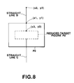
- the reduction processing for a target figure will now be described, with reference to Fig. 8.
- the reduction processing differs from the enlargement processing only in the line end coordinates adjustment processing of step A4 in Fig. 5.
- the line end coordinates adjustment processing of the reduction processing is as follows. Like in the step B1, the line end coordinates of the target straight line (straight line B) tangent to the target figure F0 are read out from the diagram data memory 14 and then stored in the areas x1 and y1 of the data memory 15. The other line end coordinates of the straight line B, that is, the start point coordinates thereof are read out from the diagram data memory 14 and then stored in the areas x2 and y2 of the data memory 15.
- the target straight line B connecting the start point coordinates (X2, Y2) and the end point coordinates (X1, Y1) is elongated so that the end point coordinates are changed to the new point coordinates (X3, Y3).
- the target straight line B is elongated so as to come into contact with the reduced target figure F0'.
- the figure modification process is performed in the similar way.
Landscapes
- Physics & Mathematics (AREA)
- General Physics & Mathematics (AREA)
- Engineering & Computer Science (AREA)
- Theoretical Computer Science (AREA)
- Processing Or Creating Images (AREA)
- Controls And Circuits For Display Device (AREA)
- Image Processing (AREA)
Applications Claiming Priority (2)
| Application Number | Priority Date | Filing Date | Title |
|---|---|---|---|
| JP44889/92 | 1992-03-02 | ||
| JP4044889A JPH05242213A (ja) | 1992-03-02 | 1992-03-02 | 線図作成装置 |
Publications (2)
| Publication Number | Publication Date |
|---|---|
| EP0559152A2 true EP0559152A2 (en) | 1993-09-08 |
| EP0559152A3 EP0559152A3 (Direct) | 1995-01-04 |
Family
ID=12704053
Family Applications (1)
| Application Number | Title | Priority Date | Filing Date |
|---|---|---|---|
| EP93103313A Withdrawn EP0559152A2 (en) | 1992-03-02 | 1993-03-02 | Diagram drawing apparatus |
Country Status (5)
| Country | Link |
|---|---|
| US (1) | US5557727A (Direct) |
| EP (1) | EP0559152A2 (Direct) |
| JP (1) | JPH05242213A (Direct) |
| KR (1) | KR970011905B1 (Direct) |
| CN (1) | CN1047679C (Direct) |
Families Citing this family (6)
| Publication number | Priority date | Publication date | Assignee | Title |
|---|---|---|---|---|
| JP3854434B2 (ja) * | 1999-09-24 | 2006-12-06 | 富士通株式会社 | 図形表示装置及び方法、並びに図形表示プログラムを格納した記憶媒体 |
| US7752253B2 (en) * | 2005-04-25 | 2010-07-06 | Microsoft Corporation | Collaborative invitation system and method |
| US20090237405A1 (en) * | 2008-03-03 | 2009-09-24 | Justsystems Corporation | Data processing apparatus and data processing method |
| JP2012256270A (ja) * | 2011-06-10 | 2012-12-27 | Sony Corp | 情報処理装置、プログラム及び情報処理方法 |
| KR101539171B1 (ko) * | 2014-01-16 | 2015-07-29 | 두산중공업 주식회사 | 설계 도면 블럭 확장 방법 및 시스템 |
| CN104842693A (zh) * | 2015-06-17 | 2015-08-19 | 沈阳飞机工业(集团)有限公司 | 一种用绘图机修改聚酯模线的方法 |
Family Cites Families (8)
| Publication number | Priority date | Publication date | Assignee | Title |
|---|---|---|---|---|
| JPS6084672A (ja) * | 1983-10-17 | 1985-05-14 | Canon Inc | 画像処理方法 |
| US4847788A (en) * | 1985-03-01 | 1989-07-11 | Hitachi, Ltd. | Graphic data processing method and system |
| GB8618665D0 (en) * | 1986-07-31 | 1986-09-10 | British Telecomm | Graphical workstation |
| US5155836A (en) * | 1987-01-27 | 1992-10-13 | Jordan Dale A | Block diagram system and method for controlling electronic instruments with simulated graphic display |
| US4868785A (en) * | 1987-01-27 | 1989-09-19 | Tektronix, Inc. | Block diagram editor system and method for controlling electronic instruments |
| JP3302011B2 (ja) * | 1990-06-11 | 2002-07-15 | キヤノン株式会社 | 図形編集方法及びその装置 |
| US5386507A (en) * | 1991-07-18 | 1995-01-31 | Teig; Steven L. | Computer graphics system for selectively modelling molecules and investigating the chemical and physical properties thereof |
| US5317508A (en) * | 1991-10-24 | 1994-05-31 | Matsushita Electric Industrial Co., Ltd. | Image editing apparatus |
-
1992
- 1992-03-02 JP JP4044889A patent/JPH05242213A/ja active Pending
-
1993
- 1993-02-09 KR KR1019930001761A patent/KR970011905B1/ko not_active Expired - Fee Related
- 1993-03-01 US US08/024,419 patent/US5557727A/en not_active Expired - Lifetime
- 1993-03-02 EP EP93103313A patent/EP0559152A2/en not_active Withdrawn
- 1993-03-02 CN CN93102003A patent/CN1047679C/zh not_active Expired - Fee Related
Also Published As
| Publication number | Publication date |
|---|---|
| US5557727A (en) | 1996-09-17 |
| KR930020301A (ko) | 1993-10-19 |
| CN1047679C (zh) | 1999-12-22 |
| KR970011905B1 (ko) | 1997-07-18 |
| EP0559152A3 (Direct) | 1995-01-04 |
| JPH05242213A (ja) | 1993-09-21 |
| CN1076040A (zh) | 1993-09-08 |
Similar Documents
| Publication | Publication Date | Title |
|---|---|---|
| JP2589999B2 (ja) | 図形入出力装置 | |
| JP3138390B2 (ja) | 図形描画装置 | |
| JP3862336B2 (ja) | 画像編集方法及び装置 | |
| JP2666538B2 (ja) | パニング制御システム | |
| JP3237898B2 (ja) | 画像図形編集装置および画像図形編集装置の処理方法 | |
| EP0535894A2 (en) | Apparatus and method for transforming a graphic pattern | |
| US5557727A (en) | Diagram drawing apparatus | |
| US6045584A (en) | Multilevel and beveled-corner design-rule halos for computer aided design software | |
| JP3391852B2 (ja) | 文書処理装置および方法 | |
| JPH064607A (ja) | データ表示装置 | |
| US6077307A (en) | Forced conformance design-rule halos for computer aided design software | |
| US5302967A (en) | Figure processing apparatus and method aided by display with ruled lines | |
| US5974243A (en) | Adjustable and snap back design-rule halos for computer aided design software | |
| JPH0434663A (ja) | 図面編集装置 | |
| JPH09146948A (ja) | 文書作成支援装置 | |
| JP2935336B2 (ja) | 図形入出力装置 | |
| JPH08272994A (ja) | 情報処理装置および情報処理方法 | |
| JP2721348B2 (ja) | 画像処理装置 | |
| JPH05143589A (ja) | 文書処理装置及びその制御方法 | |
| JP2798688B2 (ja) | 文字処理装置及び方法 | |
| JPH07319513A (ja) | プログラマブルコントローラのプログラミング装置およびそのシーケンスプログラム作成方法 | |
| JPH0744557A (ja) | 画像編集装置 | |
| JPH07282285A (ja) | 図形編集装置 | |
| JPH08115437A (ja) | 図形処理装置 | |
| JPS61131025A (ja) | グラフイツクデイスプレイ装置の図形入力方式 |
Legal Events
| Date | Code | Title | Description |
|---|---|---|---|
| PUAI | Public reference made under article 153(3) epc to a published international application that has entered the european phase |
Free format text: ORIGINAL CODE: 0009012 |
|
| 17P | Request for examination filed |
Effective date: 19930302 |
|
| AK | Designated contracting states |
Kind code of ref document: A2 Designated state(s): DE FR GB |
|
| PUAL | Search report despatched |
Free format text: ORIGINAL CODE: 0009013 |
|
| AK | Designated contracting states |
Kind code of ref document: A3 Designated state(s): DE FR GB |
|
| RAP1 | Party data changed (applicant data changed or rights of an application transferred) |
Owner name: CASIO COMPUTER CO., LTD. |
|
| 17Q | First examination report despatched |
Effective date: 19980817 |
|
| STAA | Information on the status of an ep patent application or granted ep patent |
Free format text: STATUS: THE APPLICATION HAS BEEN WITHDRAWN |
|
| 18W | Application withdrawn |
Withdrawal date: 20010911 |