EP0557224A1 - Linear sealing arrangement for door or window edges - Google Patents
Linear sealing arrangement for door or window edges Download PDFInfo
- Publication number
- EP0557224A1 EP0557224A1 EP19930440015 EP93440015A EP0557224A1 EP 0557224 A1 EP0557224 A1 EP 0557224A1 EP 19930440015 EP19930440015 EP 19930440015 EP 93440015 A EP93440015 A EP 93440015A EP 0557224 A1 EP0557224 A1 EP 0557224A1
- Authority
- EP
- European Patent Office
- Prior art keywords
- profiled
- seal according
- wall
- insulating element
- edge
- Prior art date
- Legal status (The legal status is an assumption and is not a legal conclusion. Google has not performed a legal analysis and makes no representation as to the accuracy of the status listed.)
- Withdrawn
Links
- 238000007789 sealing Methods 0.000 title claims abstract description 20
- 230000006978 adaptation Effects 0.000 claims abstract description 10
- 230000000903 blocking effect Effects 0.000 claims abstract description 4
- 230000000295 complement effect Effects 0.000 claims description 3
- 230000001154 acute effect Effects 0.000 claims description 2
- 238000012423 maintenance Methods 0.000 claims 1
- 238000009413 insulation Methods 0.000 abstract description 7
- 244000007853 Sarothamnus scoparius Species 0.000 description 6
- 239000011521 glass Substances 0.000 description 5
- 239000000463 material Substances 0.000 description 5
- 238000009434 installation Methods 0.000 description 4
- 230000002093 peripheral effect Effects 0.000 description 3
- 238000004026 adhesive bonding Methods 0.000 description 2
- XAGFODPZIPBFFR-UHFFFAOYSA-N aluminium Chemical compound [Al] XAGFODPZIPBFFR-UHFFFAOYSA-N 0.000 description 2
- 229910052782 aluminium Inorganic materials 0.000 description 2
- 239000004033 plastic Substances 0.000 description 2
- 241000772415 Neovison vison Species 0.000 description 1
- 240000008042 Zea mays Species 0.000 description 1
- 238000009432 framing Methods 0.000 description 1
- 238000003780 insertion Methods 0.000 description 1
- 230000037431 insertion Effects 0.000 description 1
- 238000000034 method Methods 0.000 description 1
- 238000012986 modification Methods 0.000 description 1
- 230000004048 modification Effects 0.000 description 1
- 239000007787 solid Substances 0.000 description 1
- XLYOFNOQVPJJNP-UHFFFAOYSA-N water Substances O XLYOFNOQVPJJNP-UHFFFAOYSA-N 0.000 description 1
- 239000002023 wood Substances 0.000 description 1
Images


Classifications
-
- E—FIXED CONSTRUCTIONS
- E06—DOORS, WINDOWS, SHUTTERS, OR ROLLER BLINDS IN GENERAL; LADDERS
- E06B—FIXED OR MOVABLE CLOSURES FOR OPENINGS IN BUILDINGS, VEHICLES, FENCES OR LIKE ENCLOSURES IN GENERAL, e.g. DOORS, WINDOWS, BLINDS, GATES
- E06B7/00—Special arrangements or measures in connection with doors or windows
- E06B7/16—Sealing arrangements on wings or parts co-operating with the wings
- E06B7/22—Sealing arrangements on wings or parts co-operating with the wings by means of elastic edgings, e.g. elastic rubber tubes; by means of resilient edgings, e.g. felt or plush strips, resilient metal strips
Definitions
- the invention relates to a self-supporting linear seal for the edge of a door or a wall.
- the seal according to the invention is very easily adaptable to doors and walls having different thicknesses, at their lower edge, or part or all of their peripheral edge.
- the devices which exist are most often assembled by gluing, by embedding or by means of screws or other similar fixing means. These devices have at their base a linear insulating element, either of the flap or joint type, or more frequently of the broom or brush type.
- sealing devices are known for doors, with height-adjustable broom.
- these are devices to be embedded in a cavity or groove formed in the edge of a door of considerable thickness, made of easily notched material such as wood. These devices are therefore not suitable for doors or glass walls.
- they are delicate to set up and adjust, and require significant tools.
- Another drawback is linked to the obligation to insert the brush-carrying rod in an intermediate piece, the latter being mounted adjustable in height in the recess recessed in the groove.
- sealing devices for thin doors adaptable to several thicknesses. These devices include a clamp open at the top, one side of which has a succession of stepped shoulders increasing the width of the clamp from the bottom to the top, the upper edge forming a tightening return.
- an additional drawback is linked to the fact that the brush is formed of a succession of tufts of bristles inserted in holes drilled at regular intervals on the underside of the device, which results in a seal. imperfect, significantly lower than that a continuous broom where the bristles are kept pinched by a profiled rod.
- the object of the invention is to remedy these drawbacks of existing devices by proposing a device that can be easily adapted to a wide range of wall thicknesses and clearance.
- the invention consists of a linear seal consisting of a profiled embedding part open upwards, forming an adaptable elastic clamp, and of a profiled part for supporting a linear element of insulation open downwards, comprising means for adjusting the position and for maintaining a linear insulating element of the broom or joint type, for example longitudinal projections forming blocking housings for the profiled strip supporting the element insulation, the two profiled parts being made in one piece, integral with one another, or juxtaposed in a horizontal plane and joined, so as to obtain a low height.
- the two parts are shaped in a single profile.
- the profile (s) can be made of aluminum, plastic, or any other material.
- the first profiled mounting part has a U-shaped cross section open upwards, the material being sufficiently elastic so that the longitudinal clamp thus formed can be easily adapted on doors of different thicknesses.
- the second profiled support part comprises a succession of holding positions making it possible to adjust the position of the insulation element for spaces to be caulked of different dimensions.
- the general inventive idea consists in making an adaptable blocking-immobilization device cooperate in a linear sealing gasket on the one hand, and on the other hand a device for adjusting the height and maintaining an insulation element, the two devices being juxtaposed by lateral offset and joined.
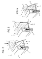
- FIG. 1 represents an overall view in section of a seal 1 according to the invention, to be placed on a edge 2 of a door or wall 3, for example made of glass, in order to seal a gap 4 on along this song.
- the lining comprises two profiled parts, a first profiled mounting part 5 and a second support part 6 for a linear sealing element 7.
- the first profiled mounting part 5 comprises an adaptation and immobilization device 8 on the edge of the door or wall.
- the gasket is arranged along the lower edge or another edge of the door or movable wall, so as to close the intermediate space of the slot type between said door or wall. and the frame or the ground.
- the adaptation and immobilization device comprises a gutter 9 of U-shaped cross section formed by the profiled part, intended to receive the edge of the door or wall, and to enclose it like pliers.
- a wing 10 of this gutter is biased elastically inward, so that its upper edge 11 is elastically constrained to bear against the opposite face of the door.
- the gutter can be made from an aluminum profile whose bottom 12 has sufficient elasticity to bring the free wing 10 inward.
- the internal angle between the bottom and the wing is an acute angle, the wing 10 being inclined inwards.
- the wing is movable from this minimum open position to a maximum open position in line with the bottom, being resiliently biased towards the first position.
- the gutter can be adapted to different wall thicknesses, and on the other hand, the immobilization by pressure of the upper edge against the wall is optimal.
- the wall is immobilized against the inner wing and possibly, but not necessarily, against the bottom, by the elastic force exerted by the outer wing.
- the device When the thickness of the wall is maximum, that is to say equal to the width of the interior bottom of the opening, the device is immobilized in the gutter by embedding ( Figures 2 and 3).
- the other part 6 of the lining carries the sealing element 7.
- This sealing element has the function of closing the slot or the intermediate space between the edge edge of the door or wall and the ground or the elements of the facing framing structure.
- the support part 6 of the sealing element 7 is offset laterally and juxtaposed with the embedding part 5 on the edge of the door or wall, the two parts generally being produced in a single profile.
- the vertical occupation of the seal 1 is minimal, so as to present a discreet aesthetic appearance, and to allow the adaptation of the device to very small intermediate spaces.
- the two profiled parts 5 and 6 are generally made in one piece or joined by their lateral faces facing each other by gluing, or other fixing method.
- the sealing element 7 consists of an insulating element 13, for example a broom or brush 14 known per se, the bristles of which are arranged vertically, of determined length, are held by a longitudinal profiled support strip 15, for example of cross-section U-shaped inverted.
- the insulating element 13 could be constituted by a solid seal, of the rubber lip type or equivalent, with or without a support strip.
- the sealing element 7 is immobilized in the lining by an adjustment and holding device 16 allowing the choice of various height positions, depending on the height of the slot to be closed. In an extreme position, the entire brush will protrude below the profile. In the other extreme position, only the ends of the bristles protrude.
- the adjustment and holding device 16 is constituted by housings such as 17 located at different heights.
- the profiled part 6 carrying the sealing element consists of a gutter 18 of U-shaped profile open downwards comprising, on the internal faces 19, 20 of its lateral wings, horizontal projections such as 21, 22 longitudinally oriented, arranged symmetrically on both sides at different heights.
- the edges of the profiled strip 15 carrying the brush bear on two corresponding protrusions, at the height necessary for the brush to exceed the desired length.
- the installation and movement of the sealing element is carried out by directly threading the rod laterally in the profiled holding part, according to the desired position.
- FIG. 8 illustrates an additional possibility of adjustment, in which the door or wall edge is clamped in the clamp at an interval 23 from the bottom 12. The sealing strip 1 is then held on the wall edge by the only force elastic gripper return.
- the rod carrying the brush has two longitudinal grooves 24,25 in the outer faces of its lateral wings.
- the projections may be replaced by longitudinal notches such as 26,27 distributed over part or all of the inner surface of the wings.
- the support strip of the insulating element will then be for example shaped in a square section having complementary notched lateral surfaces, for example lateral edges 28,29 adapted to be held in two opposite notches, the brush or the joint being in alignment with the lower edge.
- the support strip for the insulating element could also include a plurality of complementary notches on each side instead of a single side edge.
- FIG. 11 represents another variant in which the inner faces of the lateral wings of the profiled holding part of the insulating element comprise, on the one hand, longitudinal projections such as 30, 31 similar to those of the basic variant, and on the other hand, a succession of longitudinal grooves such as 32.33 arranged between said projections, and located symmetrically opposite one another.
- the insulating element is in fact carried by a flat profile in the form of a plate 34, the longitudinal edges of which are held at height by two facing grooves.
- the profiled lining according to the invention makes it possible, in its basic conformation as in one or the other variant embodiment, to isolate a gap along a straight edge, at the lower and upper edge of a door or a wall, but also along a peripheral edge, that is to say on several sides of the same door or wall. Indeed, the profile can be cut very simply at the corners. It is particularly advantageous to assemble them with a miter cut, which ensures continuity at the level of the brushes or of the insulating joint.
- the profiled strip for supporting the insulating element must be made of a flexible material, for example plastic or rubber.
- the strip or the plate could be formed in one piece with the insulating element.
- a flexible watertight flap which may advantageously include an enlarged upper edge with a profile forming a retaining strip.
Landscapes
- Engineering & Computer Science (AREA)
- Civil Engineering (AREA)
- Structural Engineering (AREA)
- Specific Sealing Or Ventilating Devices For Doors And Windows (AREA)
Abstract
Description
L'invention concerne une garniture linéaire d'étanchéité à automaintien pour le chant d'une porte ou d'une paroi.The invention relates to a self-supporting linear seal for the edge of a door or a wall.
La garniture d'étanchéité selon l'invention est adaptable très simplement à des portes et parois présentant des épaisseurs différentes, au niveau de leur chant inférieur, ou d'une partie ou de la totalité de leur chant périphérique.The seal according to the invention is very easily adaptable to doors and walls having different thicknesses, at their lower edge, or part or all of their peripheral edge.
Elle assure l'isolation thermique, phonique, et également, le cas échéant, l'étanchéité à l'eau, de divers types de portes et parois, par exemple en verre ou autres matériaux, en permettant un réglage d'adaptation à des jeux variables entre le chant de la porte ou paroi à isoler et le sol ou la partie du cadre en regard.It provides thermal and sound insulation, and also, if necessary, watertightness, of various types of doors and walls, for example made of glass or other materials, allowing adjustment to adapt to play. variables between the edge of the door or wall to be insulated and the floor or the part of the frame opposite.
Les portes en verre présentent toujours sur leur périphérie, en particulier à la base, un jeu suffisant qui permet à la porte de pivoter ou glisser sans toucher le sol, malgré les éventuelles irrégularités de celui-ci. Un inconvénient majeur lié à la présence de cette fente est d'entraîner un important courant d'air.Glass doors always have sufficient play on their periphery, in particular at the base, which allows the door to pivot or slide without touching the floor, despite any irregularities in the floor. A major drawback related to the presence of this slot is to cause a large draft.
Les dispositifs qui existent se montent le plus souvent par collage, par encastrement ou grâce à des vis ou autre moyen de fixation analogue. Ces dispositifs présentent à leur base un élément isolant linéaire, soit de type bavette ou joint, soit plus fréquemment de type balai ou brosse.The devices which exist are most often assembled by gluing, by embedding or by means of screws or other similar fixing means. These devices have at their base a linear insulating element, either of the flap or joint type, or more frequently of the broom or brush type.
Il faut donc actuellement pour chaque épaisseur de la paroi de verre des dispositifs adaptés différents. De même, comme le jeu périphérique existant autour du panneau mobile des portes est très variable, il est nécessaire, pour l'installateur, d'avoir recours à des dispositifs de hauteurs différentes à bavette ou à brosse de calfeutrage.It is therefore currently necessary for each thickness of the glass wall to have different suitable devices. Likewise, since the peripheral clearance existing around the movable panel of the doors is very variable, it is necessary for the installer to have recourse to devices of different heights with flap or caulking brush.
Certes, on connaît par exemple, par le brevet GB 2 231 360 Kleeneze, des dispositifs d'étanchéité pour des portes, à balai réglable en hauteur. Mais il s'agit de dispositifs à encastrer dans une cavité ou rainure pratiquée dans le chant d'une porte d'épaisseur importante, en matière facilement entaillable comme le bois. Ces dispositifs ne conviennent donc pas pour des portes ou parois en verre. De plus, il sont délicats à mettre en place et à ajuster, et nécessitent un outillage important.Admittedly, for example, from
Un autre inconvénient est lié à l'obligation d'insérer la baguette porte-balai dans une pièce intermédiaire, cette dernière étant montée réglable en hauteur dans le logement encastré dans la rainure.Another drawback is linked to the obligation to insert the brush-carrying rod in an intermediate piece, the latter being mounted adjustable in height in the recess recessed in the groove.
D'autre part, on connaît par exemple, par le brevet DE 91 08 651 Mink, des dispositifs d'étanchéité pour portes minces, adaptables à plusieurs épaisseurs. Ces dispositifs comportent une pince ouverte vers le haut, dont un côté présente une succession d'épaulements en escalier augmentant la largeur de la pince du bas vers le haut, le bord supérieur formant un retour de serrage.On the other hand, we know for example, from patent DE 91 08 651 Mink, sealing devices for thin doors, adaptable to several thicknesses. These devices include a clamp open at the top, one side of which has a succession of stepped shoulders increasing the width of the clamp from the bottom to the top, the upper edge forming a tightening return.
Cependant, ces dispositifs ne permettent l'adaptation qu'à des portes d'épaisseurs prédéterminées correspondant aux largeurs définies par les épaulements. D'autre part, ils ne permettent pas de réglage du balai ou joint, au contraire, la position du balai est imposée une fois le dispositif mis en place sur la porte. Egalement, leur hauteur importante imposée par la présence des épaulements d'adaptation en escalier crée un encadrement large qui dégrade l'aspect esthétique de la paroi. Leur usage présente donc de sérieux inconvénients.However, these devices only allow adaptation to doors of predetermined thicknesses corresponding to the widths defined by the shoulders. On the other hand, they do not allow adjustment of the brush or seal, on the contrary, the position of the brush is imposed once the device is in place on the door. Also, their large height imposed by the presence of the staircase adaptation shoulders creates a wide frame which degrades the aesthetic appearance of the wall. Their use therefore has serious drawbacks.
De plus, dans le type de réalisation décrit, un inconvénient supplémentaire est lié au fait que le balai est formé d'une succession de touffes de poils insérées dans des trous percés à intervalles réguliers sur la face inférieure du dispositif, ce qui entraîne une étanchéité imparfaite, nettement inférieure à celle d'un balai continu où les poils sont maintenus pincés par une baguette profilée.In addition, in the type of embodiment described, an additional drawback is linked to the fact that the brush is formed of a succession of tufts of bristles inserted in holes drilled at regular intervals on the underside of the device, which results in a seal. imperfect, significantly lower than that a continuous broom where the bristles are kept pinched by a profiled rod.
Le but de l'invention est de remédier à ces inconvénients des dispositifs existants en proposant un dispositif adaptable très simplement à un domaine étendu d'épaisseurs de parois et de jeu.The object of the invention is to remedy these drawbacks of existing devices by proposing a device that can be easily adapted to a wide range of wall thicknesses and clearance.
A cet effet, l'invention consiste en une garniture linéaire d'étanchéité constituée d'une partie profilée d'encastrement ouverte vers le haut, formant une pince élastique adaptable, et d'une partie profilée de support d'un élément linéaire d'isolation ouverte vers le bas, comprenant des moyens de réglage en position et de maintien d'un élément isolant linéaire de type balai ou joint, par exemple des saillies longitudinales formant des logements de blocage pour la baguette profilée de support de l'élément d'isolation, les deux parties profilées étant réalisées d'une seule pièce, solidaires l'une de l'autre, ou juxtaposées dans un plan horizontal et accolées, de façon à obtenir une faible hauteur.To this end, the invention consists of a linear seal consisting of a profiled embedding part open upwards, forming an adaptable elastic clamp, and of a profiled part for supporting a linear element of insulation open downwards, comprising means for adjusting the position and for maintaining a linear insulating element of the broom or joint type, for example longitudinal projections forming blocking housings for the profiled strip supporting the element insulation, the two profiled parts being made in one piece, integral with one another, or juxtaposed in a horizontal plane and joined, so as to obtain a low height.
Dans une forme de réalisation préférée, les deux parties sont conformées dans un profilé unique.In a preferred embodiment, the two parts are shaped in a single profile.
Le ou les profilés peuvent être réalisés en aluminium, en matière plastique, ou tout autre matériau.The profile (s) can be made of aluminum, plastic, or any other material.
La première partie profilée d'encastrement présente une forme de section en U ouverte vers le haut, le matériau étant suffisamment élastique pour que l'on puisse facilement adapter la pince longitudinale ainsi formée sur des portes d'épaisseurs différentes. La seconde partie profilée de support comprend une succession de positions de maintien permettant de régler la position de l'élément d'isolation pour des espaces à calfeutrer de dimensions différentes.The first profiled mounting part has a U-shaped cross section open upwards, the material being sufficiently elastic so that the longitudinal clamp thus formed can be easily adapted on doors of different thicknesses. The second profiled support part comprises a succession of holding positions making it possible to adjust the position of the insulation element for spaces to be caulked of different dimensions.
Les avantages de l'invention sont nombreux :
- . adaptabilité simple à différents types de parois et d'intervalles à calfeutrer : la garniture peut être utilisée pour une gamme étendue d'épaisseurs de paroi et de hauteurs d'intervalles ouverts ;
- . faible hauteur de l'ensemble profilé ;
- . facilité de mise en place ;
- . esthétique agréable par la présence d'une face lisse de faible hauteur ;
- . simplicité de la pose, du réglage et du changement du joint ou du balai ;
- . efficacité du calfeutrage par un balai continu ;
- . possibilité, grâce au décalage latéral, d'utiliser un balai unique au lieu de deux balais jointifs, par exemple pour l'intervalle entre deux portes battantes juxtaposées.
- . simple adaptability to different types of walls and gaps to be caulked: the lining can be used for a wide range of wall thicknesses and open gap heights;
- . low height of the profile assembly;
- . ease of installation;
- . pleasant aesthetics by the presence of a smooth face of low height;
- . simplicity of installation, adjustment and change of the seal or brush;
- . effectiveness of caulking by a continuous broom;
- . possibility, thanks to the lateral offset, to use a single brush instead of two contiguous brushes, for example for the interval between two hinged doors juxtaposed.
D'autres caractéristiques techniques et avantages de l'invention apparaîtront dans la description qui suit, donnée à titre d'exemple et accompagnée des dessins dans lesquels :
- . la figure 1 est une vue en coupe transversale d'ensemble d'une garniture d'étanchéité selon l'invention, un dispositif d'adaptation formant une pince de blocage étant écarté pour l'introduction d'un chant de paroi à isoler ;
- . les figures 2 et 3 sont des vues en perspective, en coupe, avant et après introduction d'un chant de paroi épaisse, illustrant le fonctionnement et l'adaptabilité de la pince de blocage ;
- . la figure 4 est une vue en perspective en coupe transversale équivalant à la figure 3, mais après pose sur une paroi mince ;
- . les figures 5, 6
et 7 sont des vues en coupe transversale du dispositif dans trois positions différentes de l'élément isolant, illustrant les possibilités de réglage de cet élément selon la hauteur de l'intervalle à calfeutrer ; - . la figure 8 est une vue en coupe transversale du dispositif illustrant une possibilité de réglage supplémentaire par adaptation de la pince de blocage ;
- . la figure 9 est une vue en coupe transversale du dispositif selon une variante du moyen de réglage de l'élément isolant ;
- . la figure 10 est une vue en coupe transversale du dispositif dans une autre variante du moyen de réglage de l'élément isolant.
- . la figure 11 est une vue en coupe latérale du dispositif dans une troisième variante du moyen de réglage de l'élément isolant.
- . Figure 1 is an overall cross-sectional view of a seal according to the invention, an adapter device forming a locking clip being spaced apart for the introduction of a wall edge to be insulated;
- . Figures 2 and 3 are perspective views, in section, before and after introduction of a thick wall edge, illustrating the operation and adaptability of the locking clamp;
- . Figure 4 is a perspective view in cross section equivalent to Figure 3, but after installation on a thin wall;
- . Figures 5, 6 and 7 are cross-sectional views of the device in three different positions of the insulating element, illustrating the possibilities of adjustment of this element according to the height of the gap to be caulked;
- . Figure 8 is a cross-sectional view of the device illustrating a possibility of additional adjustment by adaptation of the locking clamp;
- . Figure 9 is a cross-sectional view of the device according to a variant of the means for adjusting the insulating element;
- . Figure 10 is a cross-sectional view of the device in another variant of the means for adjusting the insulating element.
- . Figure 11 is a side sectional view of the device in a third variant of the means for adjusting the insulating element.
L'idée générale inventive consiste à faire coopérer dans une garniture linéaire d'étanchéité un dispositif adaptable de blocage-immobilisation d'une part, et d'autre part un dispositif de réglage en hauteur et maintien d'un élément d'isolation, les deux dispositifs étant juxtaposés par déport latéral et accolés.The general inventive idea consists in making an adaptable blocking-immobilization device cooperate in a linear sealing gasket on the one hand, and on the other hand a device for adjusting the height and maintaining an insulation element, the two devices being juxtaposed by lateral offset and joined.
La figure 1 représente une vue d'ensemble en coupe d'une garniture d'étanchéité 1 selon l'invention, à disposer sur un chant 2 d'une porte ou paroi 3 par exemple en verre, en vue de calfeutrer un intervalle 4 le long de ce chant. La garniture comprend deux parties profilées, une première partie profilée d'encastrement 5 et une deuxième partie de support 6 pour un élément linéaire d'étanchéité 7.FIG. 1 represents an overall view in section of a
La première partie profilée d'encastrement 5 comprend un dispositif d'adaptation et d'immobilisation 8 sur le chant de porte ou de paroi.The first profiled mounting
En général, comme représenté sur les figures, la garniture d'étanchéité est disposée le long du chant inférieur ou d'un autre chant de la porte ou paroi mobile, de façon à obturer l'espace intermédiaire de type fente entre ladite porte ou paroi et le cadre ou le sol.In general, as shown in the figures, the gasket is arranged along the lower edge or another edge of the door or movable wall, so as to close the intermediate space of the slot type between said door or wall. and the frame or the ground.
A cet effet, le dispositif d'adaptation et d'immobilisation comprend une gouttière 9 de section droite en U formée par la partie profilée, destinée à recevoir le chant de la porte ou paroi, et à l'enserrer à la manière d'une pince.To this end, the adaptation and immobilization device comprises a
Une aile 10 de cette gouttière est rappelée élastiquement vers l'intérieur, de façon que son bord supérieur 11 soit contraint élastiquement en appui contre la face en regard de la porte.A
Par exemple, la gouttière peut être réalisée à partir d'un profilé d'aluminium dont le fond 12 présente une élasticité suffisante pour ramener l'aile libre 10 vers l'intérieur.For example, the gutter can be made from an aluminum profile whose bottom 12 has sufficient elasticity to bring the
De manière préférentielle l'angle intérieur entre le fond et l'aile est un angle aigu, l'aile 10 étant inclinée vers l'intérieur. L'aile est mobile depuis cette position d'ouverture minimale jusqu'à une position d'ouverture maximale au droit du fond, en étant rappelée élastiquement vers la première position.Preferably, the internal angle between the bottom and the wing is an acute angle, the
Ainsi, d'une part la gouttière peut être adaptée à différentes épaisseurs de parois, et d'autre part, l'immobilisation par pression du bord supérieur contre la paroi est optimale.Thus, on the one hand the gutter can be adapted to different wall thicknesses, and on the other hand, the immobilization by pressure of the upper edge against the wall is optimal.
La paroi est immobilisée contre l'aile intérieure et éventuellement, mais non obligatoirement, contre le fond, par la force élastique exercée par l'aile extérieure.The wall is immobilized against the inner wing and possibly, but not necessarily, against the bottom, by the elastic force exerted by the outer wing.
Lorsque l'épaisseur de la paroi est maximale, c'est-à-dire égale à la largeur du fond intérieur de l'ouverture, le dispositif est immobilisé dans la gouttière par encastrement (figures 2 et 3).When the thickness of the wall is maximum, that is to say equal to the width of the interior bottom of the opening, the device is immobilized in the gutter by embedding (Figures 2 and 3).
L'autre partie 6 de la garniture porte l'élément d'étanchéité 7.The
Cet élément d'étanchéité a pour fonction d'obturer la fente ou l'espace intermédiaire entre le chant de bordure de la porte ou paroi et le sol ou les éléments de la structure d'encadrement en regard.This sealing element has the function of closing the slot or the intermediate space between the edge edge of the door or wall and the ground or the elements of the facing framing structure.
De façon caractéristique, la partie de support 6 de l'élément d'étanchéité 7 est déportée latéralement et juxtaposée à la partie d'encastrement 5 sur le chant de la porte ou paroi, les deux parties étant généralement réalisées dans un profilé unique.Typically, the
Ainsi, l'occupation verticale de la garniture d'étanchéité 1 est minimale, de façon à présenter un aspect esthétique discret, et à permettre l'adaptation du dispositif à des espaces intermédiaires très réduits.Thus, the vertical occupation of the
Les deux parties profilées 5 et 6 sont en général réalisées d'une seule pièce ou accolées par leurs faces latérales en regard par collage, ou autre procédé de fixation.The two profiled
L'élément d'étanchéité 7 est constitué par un élément isolant 13, par exemple un balai ou brosse 14 connue en soi dont les poils disposés verticalement, de longueur déterminée, sont maintenus par une baguette profilée longitudinale de soutien 15, par exemple de section en forme de U retourné.The sealing
Egalement, l'élément isolant 13 pourrait être constitué par un joint plein, du type à lèvre de caoutchouc ou équivalent, avec ou sans baguette de soutien.Also, the insulating
L'élément d'étanchéité 7 est immobilisé dans la garniture par un dispositif de réglage et de maintien 16 permettant le choix de diverses positions en hauteur, selon la hauteur de la fente à obturer. Dans une position extrême, la totalité de la brosse dépassera sous le profilé. Dans l'autre position extrême, seules les extrémités des poils dépassent.The sealing
Dans la version de base, le dispositif de réglage et de maintien 16 est constitué par des logements tels que 17 situés à des hauteurs différentes.In the basic version, the adjustment and holding
Plus précisément, la partie profilée 6 portant l'élément d'étanchéité est constituée d'une gouttière 18 de profil en U ouverte vers le bas comportant, sur les faces intérieures 19,20 de ses ailes latérales, des saillies horizontales telles que 21,22 orientées longitudinalement, disposées symétriquement des deux côtés à différentes hauteurs.More precisely, the profiled
Les bords de la baguette profilée 15 portant la brosse prennent appui sur deux saillies correspondantes, à la hauteur nécessaire pour que la brosse dépasse de la longueur voulue.The edges of the profiled
La mise en place et le déplacement de l'élément d'étanchéité s'effectue en enfilant directement la baguette latéralement dans la partie profilée de maintien, selon la position voulue.The installation and movement of the sealing element is carried out by directly threading the rod laterally in the profiled holding part, according to the desired position.
La figure 8 illustre une possibilité supplémentaire de réglage, dans laquelle la bordure de porte ou de paroi est enserrée dans la pince à un intervalle 23 du fond 12. La baguette d'étanchéité 1 est alors maintenue sur le chant de paroi par la seule force élastique de rappel de la pince.FIG. 8 illustrates an additional possibility of adjustment, in which the door or wall edge is clamped in the clamp at an
Dans une variante de réalisation représentée sur la figure 9, la baguette portant la brosse comporte deux rainures longitudinales 24,25 dans les faces extérieures de ses ailes latérales.In an alternative embodiment shown in Figure 9, the rod carrying the brush has two
Les dimensions de ces rainures correspondent à celles des saillies 21,22 sur la partie profilée de maintien, ce qui permet de disposer l'élément d'étanchéité selon des positions intermédiaires, en appui-maintien sur les saillies longitudinales.The dimensions of these grooves correspond to those of the
On double ainsi le nombre de positions possibles pour la brosse, ce qui réalise une grande finesse de réglage de l'isolation. L'étanchéité est ainsi optimale, sans entraîner d'usure excessive du balai ou du joint.This doubles the number of possible positions for the brush, which achieves great finesse in adjusting the insulation. Sealing is therefore optimal, without causing excessive wear of the brush or seal.
Dans une autre variante représentée sur la figure 10, les saillies pourront être remplacées par des crans longitudinaux tels que 26,27 répartis sur une partie ou l'ensemble de la surface intérieure des ailes. La baguette de soutien de l'élément isolant sera alors par exemple conformée selon une section carrée présentant des surfaces latérales crantées complémentaires, par exemple des arêtes latérales 28,29 adaptées pour être maintenues dans deux crans en regard, le balai ou le joint se trouvant dans l'alignement de l'arête inférieure. Bien entendu, la baguette de soutien de l'élément isolant pourrait également comporter une pluralité de crans complémentaires de chaque côté au lieu d'une seule arête latérale.In another variant shown in Figure 10, the projections may be replaced by longitudinal notches such as 26,27 distributed over part or all of the inner surface of the wings. The support strip of the insulating element will then be for example shaped in a square section having complementary notched lateral surfaces, for example lateral edges 28,29 adapted to be held in two opposite notches, the brush or the joint being in alignment with the lower edge. Of course, the support strip for the insulating element could also include a plurality of complementary notches on each side instead of a single side edge.
Dans cette variante, un réglage encore plus fin sera possible, par exemple pour modifier la position en hauteur de la baguette en fonction de l'usure de la brosse ou du joint.In this variant, an even finer adjustment will be possible, for example to modify the height position of the rod as a function of the wear of the brush or of the seal.
La figure 11 représente une autre variante dans laquelle les faces intérieures des ailes latérales de la partie profilée de maintien de l'élément isolant comportent, d'une part, des saillies longitudinales telles que 30,31 similaires à celles de la variante de base, et d'autre part, une succession de rainures longitudinales telles que 32,33 disposées entre lesdites saillies, et situées symétriquement en regard les unes des autres.FIG. 11 represents another variant in which the inner faces of the lateral wings of the profiled holding part of the insulating element comprise, on the one hand, longitudinal projections such as 30, 31 similar to those of the basic variant, and on the other hand, a succession of longitudinal grooves such as 32.33 arranged between said projections, and located symmetrically opposite one another.
Ces rainures permettent l'insertion d'un autre type de brosse étanche à l'air et à l'eau, et augmentent simultanément la plage de réglage. L'élément isolant est en effet porté par un profilé plat en forme de plaque 34 dont les bords longitudinaux sont maintenus à hauteur par deux rainures en regard.These grooves allow the insertion of another type of air and water tight brush, and simultaneously increase the adjustment range. The insulating element is in fact carried by a flat profile in the form of a
La garniture profilée selon l'invention permet dans sa conformation de base comme dans l'une ou l'autre variante de réalisation d'isoler un intervalle le long d'un chant rectiligne, en bordure inférieure et supérieure d'une porte ou d'une paroi, mais également le long d'un chant périphérique, c'est à dire sur plusieurs côtés d'une même porte ou paroi. En effet, le profilé peut être découpé de façon très simple aux angles. Il est notamment avantageux de les assembler avec coupe d'onglet, ce qui assure une continuité au niveau des brosses ou du joint isolant.The profiled lining according to the invention makes it possible, in its basic conformation as in one or the other variant embodiment, to isolate a gap along a straight edge, at the lower and upper edge of a door or a wall, but also along a peripheral edge, that is to say on several sides of the same door or wall. Indeed, the profile can be cut very simply at the corners. It is particularly advantageous to assemble them with a miter cut, which ensures continuity at the level of the brushes or of the insulating joint.
On peut en outre envisager de conformer la garniture linéaire suivant des formes non rectilignes, par exemple en arc de cercle, en courbes, etc..., pour s'adapter à des parois ou portes de forme complexe. Dans ces variantes de réalisations, la baguette profilée de soutien de l'élément isolant doit être réalisée dans un matériau flexible, par exemple en matière plastique ou en caoutchouc.One can also consider conforming the linear lining in non-rectilinear shapes, for example in an arc, in curves, etc., to adapt to walls or doors of complex shape. In these alternative embodiments, the profiled strip for supporting the insulating element must be made of a flexible material, for example plastic or rubber.
Par exemple, la baguette ou la plaque pourra être conformée d'une seule pièce avec l'élément isolant. Ce sera le cas notamment pour une bavette souple d'étanchéité à l'eau, qui pourra avantageusement comporter une bordure supérieure élargie à profilé formant baguette de maintien.For example, the strip or the plate could be formed in one piece with the insulating element. This will be the case in particular for a flexible watertight flap, which may advantageously include an enlarged upper edge with a profile forming a retaining strip.
Il est bien entendu qu'au-delà des moyens décrits, diverses modifications évidentes et variantes simples entrent dans le cadre de la présente invention.It is understood that beyond the means described, various obvious modifications and simple variants fall within the scope of the present invention.
Claims (11)
Applications Claiming Priority (2)
| Application Number | Priority Date | Filing Date | Title |
|---|---|---|---|
| FR9201797A FR2688021B1 (en) | 1992-02-13 | 1992-02-13 | SEALING DEVICE ADAPTABLE TO DOORS AND WALLS WITH VARIABLE GAMES AND DIFFERENT THICKNESSES. |
| FR9201797 | 1992-02-13 |
Publications (1)
| Publication Number | Publication Date |
|---|---|
| EP0557224A1 true EP0557224A1 (en) | 1993-08-25 |
Family
ID=9426735
Family Applications (1)
| Application Number | Title | Priority Date | Filing Date |
|---|---|---|---|
| EP19930440015 Withdrawn EP0557224A1 (en) | 1992-02-13 | 1993-02-12 | Linear sealing arrangement for door or window edges |
Country Status (2)
| Country | Link |
|---|---|
| EP (1) | EP0557224A1 (en) |
| FR (1) | FR2688021B1 (en) |
Cited By (4)
| Publication number | Priority date | Publication date | Assignee | Title |
|---|---|---|---|---|
| EP1439278A2 (en) | 2003-01-08 | 2004-07-21 | Firma F. Athmer | Seal, in particular contact seal or automatically lowerable floor seal for doors with adjustable mounting |
| DE102008023500A1 (en) * | 2007-11-23 | 2009-05-28 | Inge Frey | Door e.g. outer door, for use in building, has additional floor seal arranged on side of leaf pointing horizontal to floor and/or floor barrier, pointed downwards to side provided in inner area and viewed in installation direction |
| AT13115U1 (en) * | 2006-06-19 | 2013-06-15 | Guttomat Sektionaltore Gmbh | SECTIONAL |
| EP3101214B1 (en) | 2005-10-05 | 2019-04-17 | Athmer oHG | Seals, door leaves and method for mounting the seal and doors having said seals |
Citations (4)
| Publication number | Priority date | Publication date | Assignee | Title |
|---|---|---|---|---|
| BE517936A (en) * | ||||
| GB1123660A (en) * | 1967-05-05 | 1968-08-14 | Europaische H O Canfield Co G | Doors |
| GB2231360A (en) * | 1989-05-09 | 1990-11-14 | Kleeneze Limited | Draught seals for doors |
| DE9108651U1 (en) * | 1991-07-13 | 1991-11-21 | August Mink KG, 7320 Göppingen | Brush strip for sliding onto a carrier profile |
-
1992
- 1992-02-13 FR FR9201797A patent/FR2688021B1/en not_active Expired - Fee Related
-
1993
- 1993-02-12 EP EP19930440015 patent/EP0557224A1/en not_active Withdrawn
Patent Citations (4)
| Publication number | Priority date | Publication date | Assignee | Title |
|---|---|---|---|---|
| BE517936A (en) * | ||||
| GB1123660A (en) * | 1967-05-05 | 1968-08-14 | Europaische H O Canfield Co G | Doors |
| GB2231360A (en) * | 1989-05-09 | 1990-11-14 | Kleeneze Limited | Draught seals for doors |
| DE9108651U1 (en) * | 1991-07-13 | 1991-11-21 | August Mink KG, 7320 Göppingen | Brush strip for sliding onto a carrier profile |
Cited By (5)
| Publication number | Priority date | Publication date | Assignee | Title |
|---|---|---|---|---|
| EP1439278A2 (en) | 2003-01-08 | 2004-07-21 | Firma F. Athmer | Seal, in particular contact seal or automatically lowerable floor seal for doors with adjustable mounting |
| EP3101214B1 (en) | 2005-10-05 | 2019-04-17 | Athmer oHG | Seals, door leaves and method for mounting the seal and doors having said seals |
| EP3101214B2 (en) † | 2005-10-05 | 2023-02-15 | Athmer oHG | Seals, method and device for mounting the seal and doors having said seals |
| AT13115U1 (en) * | 2006-06-19 | 2013-06-15 | Guttomat Sektionaltore Gmbh | SECTIONAL |
| DE102008023500A1 (en) * | 2007-11-23 | 2009-05-28 | Inge Frey | Door e.g. outer door, for use in building, has additional floor seal arranged on side of leaf pointing horizontal to floor and/or floor barrier, pointed downwards to side provided in inner area and viewed in installation direction |
Also Published As
| Publication number | Publication date |
|---|---|
| FR2688021B1 (en) | 1998-12-31 |
| FR2688021A1 (en) | 1993-09-03 |
Similar Documents
| Publication | Publication Date | Title |
|---|---|---|
| FR2515245A1 (en) | GLAZING SYSTEM | |
| EP1400653B1 (en) | Sliding window or door, the wings being lockable against a seal on the window frame | |
| CH693858A5 (en) | Window or French window opening to strike (s) hidden (s) | |
| EP0557224A1 (en) | Linear sealing arrangement for door or window edges | |
| FR2694953A1 (en) | Connection for mounting a cross-beam on a curtain wall stiffener - is in form of saddle having single hanger with base and two thin flanges which are parallel to each other,this connection being suitable for convex, concave or flat walls | |
| FR2685136A1 (en) | PANEL, PARTICULARLY FOR CABINET DOOR, AND PARTICULARLY FOR ELECTRICAL CABINET DOOR. | |
| FR2503230A1 (en) | Waterproof hinge for shower cabinet - comprises flexible strip attached over whole length of adjacent panel edges | |
| FR2585799A1 (en) | Multifunctional seal especially for a car door, and lining for a car door opening consisting of this seal | |
| CH648090A5 (en) | Prefabricated dressings | |
| FR2633661A1 (en) | Device forming a sealing joint for flush windows | |
| EP1022427B1 (en) | Door or window plus roller shutter assembly or similar | |
| FR2922936A1 (en) | CHASSIS COMPRISING A FIXED VANTAIL | |
| EP0745750B1 (en) | Glazing panel | |
| FR2644506A1 (en) | Device for supporting glazing assemblies and in particular double glazing assemblies which are adaptable for metal doors and windows or others on a wooden frame for all openings and all types of construction | |
| FR2672918A1 (en) | PLATE FRAME ELEMENT; IN PARTICULAR FOR THE REALIZATION OF BUILDING WALLS. | |
| FR2528484A1 (en) | Fixing for juxtaposed panel dressing to wall - has profiles on wall and retaining clips anchoring panel edges | |
| FR2711054A1 (en) | Shower screen for bathtub and shower collector [holder] | |
| FR2526475A1 (en) | Double glazing window assembly - comprises opening window frame which contacts outer frame either directly or via seals | |
| FR2697400A1 (en) | Double-skinned extruded plates for outdoor equipment cabinets for housing e.g. electricity meter - have turned-in edges with three or four plates being assembled to form box, accept for back panel and door | |
| FR2823249A1 (en) | SLIDING DOOR FOR A SHELTER OF THE TYPE HAVING A STRUCTURE FORMED WITH HANGED PROFILES ON WHICH COVER PLATES ARE FIXED | |
| EP0773332A1 (en) | Sealing device between the frames of a curtainwall-type facade | |
| FR2784710A1 (en) | Double glazed window or French window with concealed operating sash | |
| FR2497867A1 (en) | Wooden door frame or window frame - incorporates gap between glass and bottom section for drainage purposes | |
| EP1045108A1 (en) | Expansible end profile for roller shutter | |
| FR2667106A1 (en) | Sealing section for caravan, camping vehicle or the like |
Legal Events
| Date | Code | Title | Description |
|---|---|---|---|
| PUAI | Public reference made under article 153(3) epc to a published international application that has entered the european phase |
Free format text: ORIGINAL CODE: 0009012 |
|
| AK | Designated contracting states |
Kind code of ref document: A1 Designated state(s): BE CH DE ES GB IT LI |
|
| RAP1 | Party data changed (applicant data changed or rights of an application transferred) |
Owner name: ETANCHEITE JUNG, SOCIETE A RESPONSABILITE LIMITEE |
|
| RIN1 | Information on inventor provided before grant (corrected) |
Inventor name: JUNG, JACQUES |
|
| STAA | Information on the status of an ep patent application or granted ep patent |
Free format text: STATUS: THE APPLICATION IS DEEMED TO BE WITHDRAWN |
|
| 18D | Application deemed to be withdrawn |
Effective date: 19940226 |