EP0554507B1 - Fluid actuated, double acting machine for punching, cutting, bending or the like - Google Patents
Fluid actuated, double acting machine for punching, cutting, bending or the like Download PDFInfo
- Publication number
- EP0554507B1 EP0554507B1 EP92115008A EP92115008A EP0554507B1 EP 0554507 B1 EP0554507 B1 EP 0554507B1 EP 92115008 A EP92115008 A EP 92115008A EP 92115008 A EP92115008 A EP 92115008A EP 0554507 B1 EP0554507 B1 EP 0554507B1
- Authority
- EP
- European Patent Office
- Prior art keywords
- fluid
- piston rod
- piston
- casing
- directional control
- Prior art date
- Legal status (The legal status is an assumption and is not a legal conclusion. Google has not performed a legal analysis and makes no representation as to the accuracy of the status listed.)
- Expired - Lifetime
Links
- 239000012530 fluid Substances 0.000 title claims description 73
- 238000004080 punching Methods 0.000 title claims description 29
- 238000005452 bending Methods 0.000 title description 3
- 238000005520 cutting process Methods 0.000 title description 3
- 230000008602 contraction Effects 0.000 claims description 22
- 238000004891 communication Methods 0.000 claims description 9
- 230000000740 bleeding effect Effects 0.000 claims description 2
- 238000010276 construction Methods 0.000 description 7
- 238000005192 partition Methods 0.000 description 6
- 229910000831 Steel Inorganic materials 0.000 description 4
- 239000010959 steel Substances 0.000 description 4
- 229910001294 Reinforcing steel Inorganic materials 0.000 description 3
- 230000006835 compression Effects 0.000 description 2
- 238000007906 compression Methods 0.000 description 2
- 230000000994 depressogenic effect Effects 0.000 description 2
- 230000006978 adaptation Effects 0.000 description 1
- 230000001419 dependent effect Effects 0.000 description 1
- 238000006073 displacement reaction Methods 0.000 description 1
- 230000000694 effects Effects 0.000 description 1
- 230000005489 elastic deformation Effects 0.000 description 1
- KJFBVJALEQWJBS-XUXIUFHCSA-N maribavir Chemical compound CC(C)NC1=NC2=CC(Cl)=C(Cl)C=C2N1[C@H]1O[C@@H](CO)[C@H](O)[C@@H]1O KJFBVJALEQWJBS-XUXIUFHCSA-N 0.000 description 1
- 230000013011 mating Effects 0.000 description 1
- 239000002184 metal Substances 0.000 description 1
- 238000012986 modification Methods 0.000 description 1
- 230000004048 modification Effects 0.000 description 1
- 229920003225 polyurethane elastomer Polymers 0.000 description 1
- 239000012858 resilient material Substances 0.000 description 1
Images


Classifications
-
- B—PERFORMING OPERATIONS; TRANSPORTING
- B23—MACHINE TOOLS; METAL-WORKING NOT OTHERWISE PROVIDED FOR
- B23D—PLANING; SLOTTING; SHEARING; BROACHING; SAWING; FILING; SCRAPING; LIKE OPERATIONS FOR WORKING METAL BY REMOVING MATERIAL, NOT OTHERWISE PROVIDED FOR
- B23D15/00—Shearing machines or shearing devices cutting by blades which move parallel to themselves
- B23D15/12—Shearing machines or shearing devices cutting by blades which move parallel to themselves characterised by drives or gearings therefor
- B23D15/14—Shearing machines or shearing devices cutting by blades which move parallel to themselves characterised by drives or gearings therefor actuated by fluid or gas pressure
-
- B—PERFORMING OPERATIONS; TRANSPORTING
- B21—MECHANICAL METAL-WORKING WITHOUT ESSENTIALLY REMOVING MATERIAL; PUNCHING METAL
- B21D—WORKING OR PROCESSING OF SHEET METAL OR METAL TUBES, RODS OR PROFILES WITHOUT ESSENTIALLY REMOVING MATERIAL; PUNCHING METAL
- B21D28/00—Shaping by press-cutting; Perforating
- B21D28/002—Drive of the tools
-
- B—PERFORMING OPERATIONS; TRANSPORTING
- B23—MACHINE TOOLS; METAL-WORKING NOT OTHERWISE PROVIDED FOR
- B23D—PLANING; SLOTTING; SHEARING; BROACHING; SAWING; FILING; SCRAPING; LIKE OPERATIONS FOR WORKING METAL BY REMOVING MATERIAL, NOT OTHERWISE PROVIDED FOR
- B23D29/00—Hand-held metal-shearing or metal-cutting devices
-
- B—PERFORMING OPERATIONS; TRANSPORTING
- B30—PRESSES
- B30B—PRESSES IN GENERAL
- B30B15/00—Details of, or accessories for, presses; Auxiliary measures in connection with pressing
- B30B15/16—Control arrangements for fluid-driven presses
- B30B15/18—Control arrangements for fluid-driven presses controlling the reciprocating motion of the ram
-
- F—MECHANICAL ENGINEERING; LIGHTING; HEATING; WEAPONS; BLASTING
- F15—FLUID-PRESSURE ACTUATORS; HYDRAULICS OR PNEUMATICS IN GENERAL
- F15B—SYSTEMS ACTING BY MEANS OF FLUIDS IN GENERAL; FLUID-PRESSURE ACTUATORS, e.g. SERVOMOTORS; DETAILS OF FLUID-PRESSURE SYSTEMS, NOT OTHERWISE PROVIDED FOR
- F15B15/00—Fluid-actuated devices for displacing a member from one position to another; Gearing associated therewith
- F15B15/18—Combined units comprising both motor and pump
-
- F—MECHANICAL ENGINEERING; LIGHTING; HEATING; WEAPONS; BLASTING
- F15—FLUID-PRESSURE ACTUATORS; HYDRAULICS OR PNEUMATICS IN GENERAL
- F15B—SYSTEMS ACTING BY MEANS OF FLUIDS IN GENERAL; FLUID-PRESSURE ACTUATORS, e.g. SERVOMOTORS; DETAILS OF FLUID-PRESSURE SYSTEMS, NOT OTHERWISE PROVIDED FOR
- F15B15/00—Fluid-actuated devices for displacing a member from one position to another; Gearing associated therewith
- F15B15/20—Other details, e.g. assembly with regulating devices
-
- Y—GENERAL TAGGING OF NEW TECHNOLOGICAL DEVELOPMENTS; GENERAL TAGGING OF CROSS-SECTIONAL TECHNOLOGIES SPANNING OVER SEVERAL SECTIONS OF THE IPC; TECHNICAL SUBJECTS COVERED BY FORMER USPC CROSS-REFERENCE ART COLLECTIONS [XRACs] AND DIGESTS
- Y10—TECHNICAL SUBJECTS COVERED BY FORMER USPC
- Y10T—TECHNICAL SUBJECTS COVERED BY FORMER US CLASSIFICATION
- Y10T29/00—Metal working
- Y10T29/53—Means to assemble or disassemble
- Y10T29/5313—Means to assemble electrical device
- Y10T29/532—Conductor
- Y10T29/53209—Terminal or connector
- Y10T29/53213—Assembled to wire-type conductor
- Y10T29/53222—Means comprising hand-manipulatable implement
- Y10T29/53226—Fastening by deformation
Definitions
- the present invention relates to a fluid actuated, double acting, linear actuating machine according to the precharacterising part of claim 1 suitable for use in the punching of sheet metal, the cutting or bending of reinforcing steel rods or tubes, clinching and stamping, among other applications. More specifically, the invention pertains to such a machine of the portable class integrally comprising a fluid pressure circuit with provisions for automatic retraction of the piston rod under fluid pressure.
- the hydraulic linear actuating machine of the type under consideration comprises a piston slidably housed in a cylinder to define a pair of opposed fluid chambers therein, a piston rod coupled to the piston and slidably extending through one end of the cylinder, and a hydraulic circuit for the delivery and discharge of a hydraulic fluid under pressure into and out of the fluid chambers.
- the machine lends itself to use for punching, cutting and other applications by having an appropriate tool such as a punch or cutter replaceably mounted to the end of the piston rod. It is used in factories where steel sheets and steel rods are worked upon, as well as at sites of construction.
- the linear actuating machine has been usually divided into two parts, one being the machine part comprising the cylinder, piston and so forth, and the other being a hydraulic unit comprising a hydraulic fluid reservoir and a pump.
- the machine part and the hydraulic unit have been intercommunicated via flexible conduits.
- the hydraulic unit For use at construction sites, the hydraulic unit has been placed in a convenient position, and the machine part has been carried about for working on desired parts.
- the machine of such conventional make is not totally devoid of advantages. Being of relatively compact, lightweight construction, the machine part is convenient for use at factories or under other tidy circumstances. At construction sites, however, where many unexpected obstacles are to be encountered, much care has been needed in moving the machine part so that the flexible conduits may not be caught by such obstacles. Further the machine part has been movable only within the range permitted by the lengths of the flexible conduits, and the hydraulic unit itself has had to be replaced for moving the machine part beyond that range. An additional inconvenience is that the flexible conduits have had to be freed from their air contents at the cost of considerable time and labor preparatory to the commencement of actual operation.
- the DE-C 34 10 137 representing the closest prior art discloses a machine part of a linear actuating machine for the connection with an external hydraulic unit generating hydraulic pressure.
- the machine part comprises a piston moving reciprocally in a casing and dividing it into two opposed fluid chambers, pressure ports for the connection of the opposed fluid chambers with the external hydraulic unit and two switches for detecting the movement of the piston rod inside a predetermined range of movement. Since the machine part disclosed is intended for use with an external hydraulic unit, flexible conduits are required for the interconnection between the machine part and the hydraulic unit. Upon disconnection of the machine part from the hydraulic unit (e.g. for changing the working site) the flexible units are depressurized resulting in a considerable loss of time for the subsequent re-pressurization.
- the integrated actuating machine Being free from elongate flexible conduits, the integrated actuating machine is highly portable and easy of use. Moreover, because of the shorter distance between pump and cylinder, the machine is good in piston response to pressurized fluid pressure. The portability and operability of the integrated actuating machine has earned it an increasing acceptance at construction sites in recent years.
- the integrated actuating machine has one drawback, however. Relying on the force of a spring for its return stroke, the machine has had difficulties in retracting the piston rod in applications where much force is required for the return stroke. Take, for example, the use of the prior art machine as a punch. The machine will encounter great frictional resistance when the work being punched is very thick or when holes are created in the work with very small clearances for dimensional accuracy. The frictional resistance can be such that the piston rod has become unretractable solely by the force of the spring.
- a conventional solution to this problem has been to mount a sleeve or sheathe of resilient material such as polyurethane rubber around the piston rod to which a punching tool is also attached. As the resilient sleeve becomes compressed upon punching, the energy thus stored in the sleeve is utilized for withdrawing the tool from within the hole.
- double acting machines have not so far existed in the art under consideration.
- Such a machine complete with a manual directional control valve, has been used for the reshaping of reinforcing steel rods or the like that have been subjected to compressive or tensile bending.
- This double acting reshaping machine presupposes such use that the extension or retraction of the piston rod is manually controlled while visually observing the bend of a reinforcing steel rod or the like.
- the above known double acting machine is not applicable to punching or like operations.
- the machine When used as a punch, for example, the machine requires manual actuation of the direction control valve each time a hole is created. Further the electric motor driving the pump has had to be temporarily set out of operation for such manual actuation of the valve.
- the pump means comprising in particular a pump drive motor, a fluid reservoir and a directional control valve are all compactly incorporated inside the casing.
- a fluid operated, double acting, linear actuating machine suitable for punching and other applications, comprising a casing having formed therein both a fluid reservoir and a piston chamber.
- a piston is reciprocably mounted in the piston chamber to define a pair of opposed fluid chambers therein, with a piston rod extending from the piston and projecting out of the casing for carrying a desired tool such as a punch.
- Pump means is also mounted to the casing for pressurizing the fluid contained in the reservoir.
- the pressurized fluid is to be delivered to either of the pair of fluid chambers via directional control valve means for extension and contraction of the piston rod.
- Sensing means senses the extension and contraction of the piston rod.
- control means connected to the directional control valve means and the sensing means for causing the piston rod to be contracted under fluid pressure upon extension.
- a punch may be replaceably mounted to the end of the piston rod, and a die may be fixed to the casing in opposed relationship to the punch.
- a hole will be created in work such as sheet steel being held between punch and die as the punch is driven through the work into the die by the extension of the piston rod.
- This piston rod extension is sensed by the sensing means, whereupon the control means cases the directional control valve means to deliver the pressurized fluid into the rod end chamber and to drain the fluid from the head end chamber.
- the die will be forcibly withdrawn out of the hole in the work.
- the fluid reservoir and the pump means comprising a pump and a drive motor therefor are both compactly mounted within the casing, so that the machine is far more operable than the conventional devices divided into a machine part and a hydraulic unit.
- Another advantage is that the machine is double acting, meaning that fluid pressure is utilized for both extension and contraction of the piston rod. Moreover, the piston rod automatically and immediately contracts upon full extension. This advantage makes the machine particularly well suited for punching, as the punch is readily and forcibly withdrawable out of the hole in the work. The clearance between the punch and the work edge defining the hole can be reduced to a minimum, and the hole can be formed with high dimensional accuracy and without taper. Additionally, the automatic, quick return of the punch will greatly expedite punching operation.
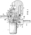
- FIG. 1 The fluid operated, linear actuating machine according to the invention is illustrated in FIG. 1 as portable hydraulic punch.
- the hydraulic punch includes an electric motor 11, complete with an armature shaft 12, mounted to the rear end, shown directed to the left in FIG. 1, of a casing 13.
- the casing 13 has fluid tightly defined therein a hydraulic fluid reservoir 14 into which the motor armature shaft 12 extends.
- a pump 15 is provided which comprises a drive cam 16 formed eccentrically on the motor armature shaft 12 for joint rotation therewith, a piston 17 to be reciprocated linearly by the drive cam via a needle bearing, and a shutoff valve 18 disposed in a fluid passageway from the reservoir 14.
- a spring 19 acts on the shutoff valve 18 to hold the fluid passageway normally closed.
- piston chamber 20 which is separated from the reservoir 14 by a partition 21.
- a piston 22 is reciprocably mounted in the piston chamber 20, dividing the same into a head end chamber 20a and a rod end chamber 20b.
- the piston 22 is shown formed in one piece with a piston rod 23 projecting out of the casing by slidably extending through the front end portion 13a of the casing 13.
- a punch 24 is mounted to the projecting end of the piston rod 23.
- the casing 13 is further formed to include a jaw 25 to which a die 26 is mounted opposite the punch 24.
- the jaw 25 has defined therein a cushioning chamber 27 accommodating an air bag 28 capable of elastic deformation for cushioning the impact of punching.
- the piston 22 is provided with relief valve means 32 for bleeding off excessive pressure from either of the head end chamber 20a and rod end chamber 20b.
- the relief valve means 32 comprises two tubular valve bodies 33a and 33b which are screwed together end to end and which is slidably mounted in a hole 31 extending through the piston 22 in a direction parallel to its axis.
- the valve bodies 33a and 33b have headed ends projecting out of the hole 31 and disposed respectively in the head end chamber 20a and the rod end chamber 20b.
- Two check balls 35 are mounted in fluid passageways 34a and 34b in the valve bodies 33a and 33b. These balls are confined in the fluid passageways 24a and 34b by pins 38. It will also be noted from FIG.
- valve bodies 33a and 33b are recessed longitudinally to provide a gap 37 which can be placed in communication with either of the two fluid chambers 20a and 20b depending upon the longitudinal position of the valve bodies 33a and 33b relative to the piston 22.
- This relief valve means 32 will become apparent in the course of the subsequent description of operation.
- FIG. 3 is a detailed illustration of fluid passageways formed in the partition 21 for the delivery of pressurized fluid from the pump 15 into the two fluid chambers 20a and 20b.
- such passageways include a pump passageway 41 in communication with the pump 15, an extension passageway 42 having an outlet port 42a open to the head end chamber 20a, and a contraction passageway 43 having an outlet port 43a open to the rod end chamber 20b. All these passageways 41, 42 and 43 communicate with a bore 44 in which a valve spool 52 is reciprocably mounted to make up a directional control valve 51.
- fluid passageways 45a and 45b are also formed in the partition 21 for draining the fluid from the fluid chambers 20a and 20b back to the reservoir 14.
- An additional fluid passageway 46, FIG. 1, extends through the casing 13 and partition 21 for communicating the reservoir 14 with the cushioning chamber 27.
- the noted pump passageway 41, extension passageway 42 and contraction passageway 43 are open to the valve bore 44 at ports 41b, 42b and 43b, respectively, which are positioned in annular undercuts in the valve bore 44.
- Such annular undercuts in the valve bore 44 alternate with annular lands or seats for sliding engagement with the valve spool 52.
- the bore lands include a first land 47 between pump passageway 41 and extension passageway 42, a second land 48 between pump passageway 41 and contraction passageway 43, a third land 49 between extension passageway 42 and drain passageway 45a, and a fourth land 50 between contraction passageway 43 and drain passageway 45b.
- the valve spool 52 is also undercut to provide a first land 53 capable of sliding engagement with either of the first 47 and third 49 bore lands, and a second land 54 capable of sliding engagement with either of the second 48 and fourth 50 bore lands.
- the valve spool 52 is coupled at one end to a solenoid 55 thereby to be actuated longitudinally between the FIG. 3 position and that of FIG. 4.
- FIG. 1 indicates at 57 a switch actuator pin planted in the piston rod 23 and extending radially outwardly therefrom.
- the switch actuator pin 57 extends through a slot 58 in the front end portion 13a of the casing 13 for actuating a first limit switch 59a upon retraction of the piston rod 23, and a second limit switch 59b upon extension of the piston rod.
- the pin 57 may be shaped and sized to travel in sliding contact with the casing front end portion 13a for serving the additional purpose of preventing the piston rod 23 from angular displacement.
- FIG. 1 also shows electric control means 61 mounted to the casing 13 for controlling the operations of the electric motor 11 and a solenoid actuated directional control valve 51.
- the two limit switches 59a and 59b are connected in circuit with a control means 61 in order to provide electric piston position signals needed for automatically operating the directional control valve 51 in accordance with the invention.
- a pushbutton start switch 61a is also connected in circuit with the control means 61. The start switch 61a is to be depressed for the commencement of punching operation.
- Seen at 62a and 62b in FIG. 1 are a pair of handgrips screwed into the casing 13 and projecting laterally in opposite directions therefrom. These handgrips are to be grasped by the hands in use of the punching machine 10.
- the start switch 61a is disposed adjacent the right hand handgrip 62a for the ease of manipulation.
- FIG. 1 is shown the punching machine 10 in its normal state, with the piston rod 23 retracted.
- the switch actuator pin 57 on the piston rod 23 is therefore engaged with the first limit switch 59a.
- the head of the head end chamber relief valve body 33a is caught between partition 21 and piston 22, with the ball 35 closing the fluid passageway 34a against fluid flow from head end chamber 20a into rod end chamber 20b.
- the spool 52 of the directional control valve 51 is held retracted as depicted in FIG. 3, holding the pump passageway 41 in communication with the contraction passageway 43 and out of communication with the extension passageway 42.
- the work such as a piece of sheet steel to be punched may be held between punch 24 and die 26. Then the start switch 61a may be depressed. The resulting rotation of the electric drive motor 11 will be translated into the linear reciprocation of the pump piston 17 by the eccentric drive cam 16 on the motor armature shaft 12. The hydraulic fluid in the reservoir 14 will be pressurized by the reciprocating piston 17 and forced into the pump passageway 41 and thence into the bore 44, FIG. 3, of the solenoid actuated directional control valve 51.
- the depression of the start switch 61a will result also in the energization of the solenoid 55, with the consequent travel of the valve spool 53 from its FIG. 3 position to that of FIG. 4.
- the valve spool 53 when thus actuated to the FIG. 4 position will discommunicate the pump passageway 41 from the contraction passageway 43 and, instead, communicate the pump passageway 41 with the extension passageway 42.
- the switch actuator pin 57 on the piston rod 23 will disengage the first limit 59a immediately when the piston 22 starts traveling on its extension stroke, so that the first limit switch 59a will signal the control means 61 to that effect. Then, upon extension of the piston rod 23 to a predetermined degree, the pin 57 will engage the second limit switch 59b. Inputting the piston position signal from the second limit switch 59b, the control means 61 will cause the solenoid 55 to retract the valve spool 52 from its FIG. 4 position back to that of FIG. 3, in which latter position the extension passageway 42 will communicate with the drain passageway 42a. The fluid will therefore be drained from the head end chamber 20a into the reservoir 14. Further, since the valve spool 52 when in the FIG. 3 position communicates the pump passageway 41 with the contraction passageway 43, the pressurized fluid will be directed into the rod end chamber 20b. The punch 24 will be withdrawn out of the hole that has been formed in the work as the piston rod 23 is retracted under fluid pressure.
- One cycle of punching operation will come to an end as the pin 57 subsequently actuates the first limit switch 59 to cause the control means 61 to set the drive motor 11 out of rotation upon, full retraction of the piston rod 23.
- the drive motor 11 has been in operation throughout the foregoing cycle of operation, so that the punch 24 can be driven forward to create a hole in the work, and withdrawn therefrom, quickly and automatically.
- the directional control valve 51 may fail to operate when the piston rod 23 is fully extended or contracted, resulting in the continued delivery of the pressurized fluid into either of the head end chamber 20a and rod end chamber 20b.
- the relief valve means 32 will then operate as follows to bleed off excessive pressure from either chamber.
- the directional control valve 51 has somehow failed to operate when the piston 22 is in the fully retracted position of FIG. 2. Since then the valve body 33a butts against the partition 21, the gap 37 is thereby discommunicate from the head end chamber 20a. However, the continued delivery of pressurized fluid into the rod end chamber 20b will result in the dislodgement of the check ball 35 from the seat formed in the fluid passageway 34a in the valve body 33a. Thus the excess pressure in the rod end chamber 20b will be admitted into the head end chamber 20a through the gap 37 and passageway 34a. The directional control valve 51 is then in the FIG.
- the complete cycle of punching operation takes place automatically by simple depression of the pushbutton start switch 61a, with the drive motor 11 maintained in continuous rotation.
- the punching machine 10 is also notable for its improved operability as the pump 15, reservoir 14, and pump drive motor 11 are all compactly incorporated into the machine.
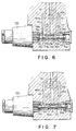
- FIGS. 6 and 7 show another preferred form of directional control valve suitable for use in the punching machine 10 in place of the valve 51.
- the alternate directional control valve includes a spool 71 slidably mounted a space 75 within three tubular seat members 76a, 76b and 76c which in turn are immovably mounted in alignment in a valve bore 74.
- These seat members 76a-76c are spaced longitudinally from one another, and the extension passageway 42 and contraction passageway 43, which communicate as aforesaid with the head end chamber and rod end chamber of the punching machine, are open respectively to the two spacings provided between the seat members.
- the valve spool 71 has formed thereon two lands 72 and 73 which are loosely received respectively in the two spacings between the seat members 76a-76c.
- the lands 72 and 73 have tapered sides 72a, 72b, 73a and 73b for movement into and out of pressure tight contact with the opposed ends of the seat members.
- valve spool 71 is received in the tubular seat members 76a-76c with a clearance or gap 77. This gap is in constant communication with the pump passageway 41 and two drain passageways 45a and 45b via holes 78b, 78a and 78c which are formed in the seat members 76a-76c, respectively.
- the solenoid 55 actuates the valve spool 71 between the positions of FIGS. 6 and 7.
- the spool 71 When the spool 71 is in the FIG. 6 position, the tapered side 72b of the land 72 is held against one end of the intermediate seat member 76b, discommunicating the pump passageway 41 from the extension passageway 42.
- the other land 73 of the spool 71 is out of contact with the intermediate seat member 76b, so that the pump passageway 41 is in communication with the contraction passageway 43.
- the pressurized fluid from the pump 15 is therefore directed into the rod end chamber 20b, with the consequent retraction of the piston rod 23.
- the tapered side 73a of the land 73 is held against one end of the intermediate seat member 76b, discommunicating the pump passageway 41 from the contraction passageway 43.
- the other land 72 of the spool 71 is out of contact with the intermediate seat member 76b, communicating the pump passageway 41 with the extension passageway 42.
- the pressurized fluid from the pump is therefore directed into the head end chamber for the extension of the piston rod.
- a pair of proximity switches 81a and 81b may be employed in lieu of the limit switches 59a and 59b of FIG. 5 for detecting the extreme positions of the piston 22 of the FIG. 1 punching machine 10. Disposed adjacent the opposite ends of the slot 58 in the casing, the proximity switches 81a and 81b are to be actuated when the switch actuator pin 57 on the piston rod comes sufficiently near the switches. Such noncontact actuation of the switches assures their longer useful life.
- FIG. 9 is shown alternate relief valve means for use in the FIG. 1 punching machine 10 in place of the relief valve means 32 shown in FIG. 2.
- the alternate relief valve means comprises two balls 92a and 92b mounted within a hole or relief passageway 91 extending through the piston 22 for intercommunicating the head end chamber 20a and rod end chamber 20b.
- the relief passageway 91 has its opposite ends constricted to prevent the dislodgement of the balls 92a and 92b.
- a helical compression spring 93 urges the balls 92a and 92b against these constricted ends of the relief passageway 91.
Landscapes
- Engineering & Computer Science (AREA)
- Mechanical Engineering (AREA)
- Physics & Mathematics (AREA)
- Fluid Mechanics (AREA)
- General Engineering & Computer Science (AREA)
- Press Drives And Press Lines (AREA)
- Actuator (AREA)
- Fluid-Pressure Circuits (AREA)
- Perforating, Stamping-Out Or Severing By Means Other Than Cutting (AREA)
Applications Claiming Priority (2)
| Application Number | Priority Date | Filing Date | Title |
|---|---|---|---|
| JP04003222A JP3102939B2 (ja) | 1992-01-10 | 1992-01-10 | 複動型油圧作動装置 |
| JP3222/92 | 1992-01-10 |
Publications (2)
| Publication Number | Publication Date |
|---|---|
| EP0554507A1 EP0554507A1 (en) | 1993-08-11 |
| EP0554507B1 true EP0554507B1 (en) | 1997-06-04 |
Family
ID=11551418
Family Applications (1)
| Application Number | Title | Priority Date | Filing Date |
|---|---|---|---|
| EP92115008A Expired - Lifetime EP0554507B1 (en) | 1992-01-10 | 1992-09-02 | Fluid actuated, double acting machine for punching, cutting, bending or the like |
Country Status (5)
| Country | Link |
|---|---|
| US (1) | US5282378A (ja) |
| EP (1) | EP0554507B1 (ja) |
| JP (1) | JP3102939B2 (ja) |
| DE (1) | DE69220202T2 (ja) |
| ES (1) | ES2104779T3 (ja) |
Families Citing this family (26)
| Publication number | Priority date | Publication date | Assignee | Title |
|---|---|---|---|---|
| US5598737A (en) * | 1993-12-03 | 1997-02-04 | Kabushiki Kaisha Ogura | Portable, power driven punch press for working on steel frame members |
| US5553478A (en) * | 1994-04-08 | 1996-09-10 | Burndy Corporation | Hand-held compression tool |
| US5622076A (en) * | 1995-05-04 | 1997-04-22 | Welty; Robert E. | Portable hydraulic punch |
| US5727417A (en) * | 1995-09-22 | 1998-03-17 | Greenlee Textron Inc. | Portable battery powered crimper |
| JP3792307B2 (ja) * | 1996-08-26 | 2006-07-05 | 株式会社オグラ | 油圧作動装置 |
| JP3300917B2 (ja) * | 1996-11-01 | 2002-07-08 | 株式会社泉精器製作所 | カウンタ付き油圧式圧縮装置 |
| DE19649932A1 (de) * | 1996-12-02 | 1998-06-04 | Klauke Gmbh Gustav | Hydraulisches Handgerät |
| US6453719B1 (en) * | 2000-07-28 | 2002-09-24 | Fci Usa, Inc. | Hydraulic tool with forward surrounding reservoir |
| BE1013823A3 (nl) * | 2000-11-03 | 2002-09-03 | All Mecanic Nv | Handgereedschap. |
| WO2003050923A1 (en) * | 2001-12-11 | 2003-06-19 | Mss Power Systems Pty Ltd | Hydraulic crimping apparatus |
| US6668613B2 (en) * | 2002-04-09 | 2003-12-30 | Fci Americas Technology, Inc. | Hydraulic compression tool and hydraulic compression tool motor |
| US6684679B2 (en) * | 2002-05-31 | 2004-02-03 | Yu-Fu Hsieh | Pneumatic metal-work tool |
| JP3902766B2 (ja) * | 2003-01-06 | 2007-04-11 | 株式会社オグラ | 複動型油圧作動装置 |
| ITBS20030093A1 (it) * | 2003-10-10 | 2005-04-11 | Gimatic Spa | Attrezzo di taglio o di presa con dispositivo per rilevarne il compimento dell'azione. |
| US20080302167A1 (en) * | 2007-06-08 | 2008-12-11 | Fci Americas Technology, Inc. | Hydraulic tool with multiple handles |
| US20100300279A1 (en) * | 2009-06-02 | 2010-12-02 | George Kadlicko | Point Of Use Actuator |
| DE102009026273A1 (de) * | 2009-07-02 | 2011-01-05 | Gustav Klauke Gmbh | Hydraulisches Pressgerät |
| US20110126679A1 (en) * | 2009-12-02 | 2011-06-02 | Weber Maschinenbau Gmbh Breidenbach | Apparatus for slicing food products |
| EP2718067B1 (en) | 2011-04-11 | 2023-10-11 | Milwaukee Electric Tool Corporation | Hydraulic hand-held knockout punch driver |
| US9393711B2 (en) * | 2011-04-11 | 2016-07-19 | Milwaukee Electric Tool Corporation | Hand-held knockout punch driver |
| US9016317B2 (en) | 2012-07-31 | 2015-04-28 | Milwaukee Electric Tool Corporation | Multi-operational valve |
| US10226826B2 (en) | 2013-10-22 | 2019-03-12 | Milwaukee Electric Tool Corporation | Hydraulic power tool |
| US10000007B2 (en) | 2015-06-10 | 2018-06-19 | Milwaukee Electric Tool Corporation | PEX expanding tool |
| US9862137B2 (en) | 2015-04-20 | 2018-01-09 | Milwaukee Electric Tool Corporation | PEX expanding tool |
| JP7008321B2 (ja) * | 2017-10-03 | 2022-01-25 | 育良精機株式会社 | 油圧作動装置及びパンチャー |
| CN114101775B (zh) * | 2021-12-06 | 2023-08-29 | 马鞍山市中元机床制造有限公司 | 一种光电自检定位前托式自动剪板机装置及驱控方法 |
Family Cites Families (14)
| Publication number | Priority date | Publication date | Assignee | Title |
|---|---|---|---|---|
| FR1125999A (fr) * | 1955-05-04 | 1956-11-12 | Offray & Cie | Dispositif formant limiteur et réducteur automatique de pression en produisant l'arrêt à fin de course, pour vérins hydrauliques à double effet |
| US3165140A (en) * | 1961-07-19 | 1965-01-12 | Cincinnati Shaper Co | Multiple stop device for press brakes and the like |
| CH459766A (de) * | 1967-05-12 | 1968-07-15 | Huegi Wilfried | Hydraulische Presse mit einem doppelt wirkenden Presskolben |
| DE2024890C3 (de) * | 1970-05-22 | 1978-11-16 | Rudolf 7031 Holzgerlingen Bock | Hydraulische Schere, insbesondere zum Schneiden von Rundstahlstäben |
| SU456333A2 (ru) * | 1973-01-12 | 1975-01-05 | Государственный Проектный Институт "Тяжпромэлектропроект" | Ручной электрофицированный гидравлический пресс дл опрессовки кабельных наконечников |
| JPS6346069Y2 (ja) * | 1980-06-27 | 1988-11-30 | ||
| JPS6023897B2 (ja) * | 1982-07-06 | 1985-06-10 | 平田プレス工業株式会社 | シャットハイト調整に応動するボルスタ上限位置検出スイッチ取付位置自動調整装置 |
| DE3410137C1 (de) * | 1984-03-20 | 1985-05-15 | Benteler-Werke Ag Werk Neuhaus, 4790 Paderborn | Hydraulische Stanzvorrichtung |
| JPS6448424A (en) * | 1987-08-19 | 1989-02-22 | Fujitsu Ltd | Etching method of semiconductor substrate having stepped section |
| CA1335638C (en) * | 1987-12-04 | 1995-05-23 | Kinshirou Naito | Method and device for controlling the stroke of a press |
| US4936126A (en) * | 1988-05-17 | 1990-06-26 | Daiichi Electric Co., Ltd. | Press brake with a displacement sensor of electric signal output |
| DE68915434D1 (de) * | 1989-03-31 | 1994-06-23 | Japan Storage Battery Co Ltd | Nockenantrieb und angetriebenes Hydraulikwerkzeug. |
| US5195354A (en) * | 1989-03-31 | 1993-03-23 | Japan Storage Battery Co., Ltd. | Cam crank mechanism and motor driven hydraulic tool |
| US5152162A (en) * | 1990-06-27 | 1992-10-06 | Burndy Corporation | System and method for crimping articles |
-
1992
- 1992-01-10 JP JP04003222A patent/JP3102939B2/ja not_active Expired - Fee Related
- 1992-09-02 EP EP92115008A patent/EP0554507B1/en not_active Expired - Lifetime
- 1992-09-02 ES ES92115008T patent/ES2104779T3/es not_active Expired - Lifetime
- 1992-09-02 US US07/939,332 patent/US5282378A/en not_active Expired - Fee Related
- 1992-09-02 DE DE69220202T patent/DE69220202T2/de not_active Expired - Fee Related
Also Published As
| Publication number | Publication date |
|---|---|
| DE69220202D1 (de) | 1997-07-10 |
| EP0554507A1 (en) | 1993-08-11 |
| DE69220202T2 (de) | 1997-11-13 |
| JPH05187415A (ja) | 1993-07-27 |
| US5282378A (en) | 1994-02-01 |
| JP3102939B2 (ja) | 2000-10-23 |
| ES2104779T3 (es) | 1997-10-16 |
Similar Documents
| Publication | Publication Date | Title |
|---|---|---|
| EP0554507B1 (en) | Fluid actuated, double acting machine for punching, cutting, bending or the like | |
| US5233749A (en) | Hydraulic actuator | |
| CN100534682C (zh) | 带有快进式压头的液压工具 | |
| JPS6346069Y2 (ja) | ||
| US5105622A (en) | Hydraulic unit for driving a tool | |
| CN208020139U (zh) | 液压工作装置 | |
| EP4025389B1 (en) | Tool with hydraulic system for regenerative extension and two-speed operation | |
| JPH02218873A (ja) | 圧縮空気で作動されるポンプ装置 | |
| US5802850A (en) | Hydraulic machine having an improved air bag | |
| CN109026862B (zh) | 压力可调的弯曲机 | |
| US5064005A (en) | Impact hammer and control arrangement therefor | |
| US7080589B2 (en) | Hydraulic cylinder | |
| CN211820145U (zh) | 一体式电动液压折弯机 | |
| EP0008292B1 (en) | Hydraulic nailing pistol | |
| JP3610763B2 (ja) | 手持ち動力工具 | |
| JP2020040157A (ja) | 電動工具 | |
| CN218396198U (zh) | 一种换向装置及电动液压工具 | |
| CN211867654U (zh) | 一种便携式液压工具 | |
| CN215657540U (zh) | 钢筋弯曲机 | |
| CN215200554U (zh) | 一种用于柱塞滑靴自动压装的冲压机构 | |
| SU888251A1 (ru) | Ручной инструмент дл обжима кабельных наконечников | |
| JPH078098Y2 (ja) | 携帯用油圧式加工機 | |
| EP0244450B1 (en) | Portable operating apparatus with interchangeable heads | |
| JPH0417295Y2 (ja) | ||
| JPS62255077A (ja) | 手動式液力ポンプ |
Legal Events
| Date | Code | Title | Description |
|---|---|---|---|
| PUAI | Public reference made under article 153(3) epc to a published international application that has entered the european phase |
Free format text: ORIGINAL CODE: 0009012 |
|
| 17P | Request for examination filed |
Effective date: 19920902 |
|
| AK | Designated contracting states |
Kind code of ref document: A1 Designated state(s): DE ES FR GB IT SE |
|
| 17Q | First examination report despatched |
Effective date: 19950227 |
|
| GRAG | Despatch of communication of intention to grant |
Free format text: ORIGINAL CODE: EPIDOS AGRA |
|
| GRAH | Despatch of communication of intention to grant a patent |
Free format text: ORIGINAL CODE: EPIDOS IGRA |
|
| GRAH | Despatch of communication of intention to grant a patent |
Free format text: ORIGINAL CODE: EPIDOS IGRA |
|
| GRAA | (expected) grant |
Free format text: ORIGINAL CODE: 0009210 |
|
| AK | Designated contracting states |
Kind code of ref document: B1 Designated state(s): DE ES FR GB IT SE |
|
| REF | Corresponds to: |
Ref document number: 69220202 Country of ref document: DE Date of ref document: 19970710 |
|
| ET | Fr: translation filed | ||
| ITF | It: translation for a ep patent filed | ||
| REG | Reference to a national code |
Ref country code: ES Ref legal event code: FG2A Ref document number: 2104779 Country of ref document: ES Kind code of ref document: T3 |
|
| PLBE | No opposition filed within time limit |
Free format text: ORIGINAL CODE: 0009261 |
|
| STAA | Information on the status of an ep patent application or granted ep patent |
Free format text: STATUS: NO OPPOSITION FILED WITHIN TIME LIMIT |
|
| 26N | No opposition filed | ||
| REG | Reference to a national code |
Ref country code: GB Ref legal event code: IF02 |
|
| PGFP | Annual fee paid to national office [announced via postgrant information from national office to epo] |
Ref country code: ES Payment date: 20020814 Year of fee payment: 11 |
|
| PGFP | Annual fee paid to national office [announced via postgrant information from national office to epo] |
Ref country code: GB Payment date: 20030827 Year of fee payment: 12 |
|
| PG25 | Lapsed in a contracting state [announced via postgrant information from national office to epo] |
Ref country code: ES Free format text: LAPSE BECAUSE OF NON-PAYMENT OF DUE FEES Effective date: 20030903 |
|
| PGFP | Annual fee paid to national office [announced via postgrant information from national office to epo] |
Ref country code: SE Payment date: 20030916 Year of fee payment: 12 |
|
| PGFP | Annual fee paid to national office [announced via postgrant information from national office to epo] |
Ref country code: FR Payment date: 20031002 Year of fee payment: 12 |
|
| PGFP | Annual fee paid to national office [announced via postgrant information from national office to epo] |
Ref country code: DE Payment date: 20031126 Year of fee payment: 12 |
|
| PG25 | Lapsed in a contracting state [announced via postgrant information from national office to epo] |
Ref country code: GB Free format text: LAPSE BECAUSE OF NON-PAYMENT OF DUE FEES Effective date: 20040902 |
|
| PG25 | Lapsed in a contracting state [announced via postgrant information from national office to epo] |
Ref country code: SE Free format text: LAPSE BECAUSE OF NON-PAYMENT OF DUE FEES Effective date: 20040903 |
|
| REG | Reference to a national code |
Ref country code: ES Ref legal event code: FD2A Effective date: 20030903 |
|
| PG25 | Lapsed in a contracting state [announced via postgrant information from national office to epo] |
Ref country code: DE Free format text: LAPSE BECAUSE OF NON-PAYMENT OF DUE FEES Effective date: 20050401 |
|
| GBPC | Gb: european patent ceased through non-payment of renewal fee |
Effective date: 20040902 |
|
| EUG | Se: european patent has lapsed | ||
| PG25 | Lapsed in a contracting state [announced via postgrant information from national office to epo] |
Ref country code: FR Free format text: LAPSE BECAUSE OF NON-PAYMENT OF DUE FEES Effective date: 20050531 |
|
| REG | Reference to a national code |
Ref country code: FR Ref legal event code: ST |
|
| PG25 | Lapsed in a contracting state [announced via postgrant information from national office to epo] |
Ref country code: IT Free format text: LAPSE BECAUSE OF NON-PAYMENT OF DUE FEES;WARNING: LAPSES OF ITALIAN PATENTS WITH EFFECTIVE DATE BEFORE 2007 MAY HAVE OCCURRED AT ANY TIME BEFORE 2007. THE CORRECT EFFECTIVE DATE MAY BE DIFFERENT FROM THE ONE RECORDED. Effective date: 20050902 |