EP0244450B1 - Portable operating apparatus with interchangeable heads - Google Patents
Portable operating apparatus with interchangeable heads Download PDFInfo
- Publication number
- EP0244450B1 EP0244450B1 EP86906314A EP86906314A EP0244450B1 EP 0244450 B1 EP0244450 B1 EP 0244450B1 EP 86906314 A EP86906314 A EP 86906314A EP 86906314 A EP86906314 A EP 86906314A EP 0244450 B1 EP0244450 B1 EP 0244450B1
- Authority
- EP
- European Patent Office
- Prior art keywords
- head
- piston
- rod
- operating
- flange
- Prior art date
- Legal status (The legal status is an assumption and is not a legal conclusion. Google has not performed a legal analysis and makes no representation as to the accuracy of the status listed.)
- Expired
Links
Images


Classifications
-
- B—PERFORMING OPERATIONS; TRANSPORTING
- B25—HAND TOOLS; PORTABLE POWER-DRIVEN TOOLS; MANIPULATORS
- B25B—TOOLS OR BENCH DEVICES NOT OTHERWISE PROVIDED FOR, FOR FASTENING, CONNECTING, DISENGAGING OR HOLDING
- B25B33/00—Hand tools not covered by any other group in this subclass
-
- B—PERFORMING OPERATIONS; TRANSPORTING
- B23—MACHINE TOOLS; METAL-WORKING NOT OTHERWISE PROVIDED FOR
- B23D—PLANING; SLOTTING; SHEARING; BROACHING; SAWING; FILING; SCRAPING; LIKE OPERATIONS FOR WORKING METAL BY REMOVING MATERIAL, NOT OTHERWISE PROVIDED FOR
- B23D15/00—Shearing machines or shearing devices cutting by blades which move parallel to themselves
- B23D15/12—Shearing machines or shearing devices cutting by blades which move parallel to themselves characterised by drives or gearings therefor
- B23D15/14—Shearing machines or shearing devices cutting by blades which move parallel to themselves characterised by drives or gearings therefor actuated by fluid or gas pressure
-
- B—PERFORMING OPERATIONS; TRANSPORTING
- B23—MACHINE TOOLS; METAL-WORKING NOT OTHERWISE PROVIDED FOR
- B23D—PLANING; SLOTTING; SHEARING; BROACHING; SAWING; FILING; SCRAPING; LIKE OPERATIONS FOR WORKING METAL BY REMOVING MATERIAL, NOT OTHERWISE PROVIDED FOR
- B23D31/00—Shearing machines or shearing devices covered by none or more than one of the groups B23D15/00 - B23D29/00; Combinations of shearing machines
Definitions
- the present invention relates to a portable operating apparatus with interchangeable heads.
- the known operating machines such as shears, bar benders, cutting machines and so on, consist of a unit comprising an electrical or internal combustion motor driving an oil pump which causes the displacement of a piston operating a tool.
- CH-A-384 501 describes a portable multi-role operating apparatus according to the preamble of claim 1.
- the portable operating apparatus substantially comprises a body 1 provided with handle 2, and having at one end an electrical motor 3 and at the other end a flange 4 supporting the heads.
- the body 1 comprises an upper tank 5 for the fluid, communicating with a cylindric hollow 6, in which a piston pump 7 is housed.
- the pump 7 comprises a three- lobes 10 body having a middle cylindric hollow 8, at which cylindric radial seats 9 end up, foreseen in the three lobes 10.
- a middle cylindric hollow 8 at which cylindric radial seats 9 end up, foreseen in the three lobes 10.
- each cylindric seat 9 At the outer end of each cylindric seat 9, beyond the corresponding groove 12, holes 13 are foreseen. Ducts 13 end up at these holes 13 connecting the seat 9 with the front surface of the pump (at the right hand in figure 2).
- the ducts 14 are provided with non-return valves (not shown in the drawings) to allow the unidirectional flow of the fluid pumped by the pistons 11.
- Each piston 11 is kept with its inner end projecting inside the cylindric hollow 8 and is also elastically kept into touch with a common annular element 15 having diameter less than the diameter of the hollow 8 and housed inside this.
- An eccentric pin 16 bound to the shaft of the motor 3, is engaged within the annular element 15.
- a traditional cooling fan 17 is applied.
- a cylindric chamber 18 is foreseen inside the body 1, coaxially with the pump 7. Within said chamber the head of a piston 19 is displaceable, having the rod 20 which comes out from the flange 4.
- a longitudinal duct 21 is foreseen, connecting the tank 5 with the chamber 18 downstream the head of the piston 19 through a short radial duct 22.
- a cylindric seat 23 is foreseen housing a safety-valve.
- This valve comprise a point- shaped stem 25, pushed by a solenoidal spring 26 to close a duct 28 connecting the seat 23 with the chamber 18 upstream the head of the piston 19.
- the elastic reaction of the spring 26 is adjusted by a bush 26 screwed in a corresponding threaded portion of the seat 23.
- ducts 29 are foreseen, coaxially extending from the ducts 14 of the pump 7.
- a further duct 30 is foreseen, connecting this chamber with the tank 5 through a valve 31, which in the illustrated embodiment is handly-actuable by the user.
- the head of the piston 19 is provided with a mushroom-shaped valve 32, having its head 33 facing two passing holes 34 made in the same head of the piston 19.
- a solenoidal spring 35 keeps elsatically spaced apart said head 33 from the head of the piston 19.
- a further solenoidal spring 36 is foreseen around to the rod 20 of the piston 19.
- the flange 4 has the central hole, through which the rod 20 passes, provided with a longitudinal groove guiding a spline 38 applied to said rod 20, which therefore can axially be displaced but cannot rotate around its longitudinal axis.
- the outer side surface of the flange 4 is provided with a perimetric groove 39, to be engaged by a corresponding edge of a removable ring 40.
- This ring consists of two portions hinged at one end and provided with mutual bond means at the other end.
- the other edge of the ring 40 is engageable with a corresponding groove 41 foreseen in the flange 42 of the head of the tool, and in particular on the shearing head in figure 5.
- the portable apparatus according to the invention operates as follows:
- the solenoidal spring 36 keeps the head of the piston 19 adhering to the rear wall of the cylindric chamber 18, so that the head of the valve 32 adheres to the head of the piston 19 and closes the holes 34.
- the stem of the valve 32 interacts with the front wall of the chamber 18 axially displacing backward the same valve 32 and removing its head from the head of the piston 19, thus opening the holes 34. In this way the oil further entering into the chamber 18 passes through these holes 34 and returns, through the duct 21, into the tank 5.
- the user disengages the portions of the ring 40, takes away the shearing head 43 and replaces it with another one fit to carry out the new function.
- a bending head is shown, to which a semicylindric mould 47 is bound, complementary to a movable U-shaped counter-mould 48, actuated by the rod 20 of the piston 19. It is clear that, during the actuating of the apparatus and therefore during the advancement of the counter-mould 48 towards the mould 47, the bending of a metal bar interplaced between them is caused.
- FIG 8 a second embodiment of a bending head is shown in which the movable counter-mould 49 is provided with a pair of rollers 50, allowing to carry out the soft bending of the metal bar, without any stretching.
- a snips head 51 is shown having coplanar blades 52. These blades are articulated to two pins 53 and are kept in open condition by the elastic reaction of two springs 54. A wedge 55 is placed between the arms of the blades 52, beyond their articulation pins 53.
- a snips head 56 is shown having the blades 57 scissors-actuable.
- the blades 57 are articulated to a pin 58 and two pushers 60 are toggle-articulated to the arms 59 of said blades and to a block 61, which is obliged to move along two longitudinal holes 62 made in the body or the head 56. While operating, the head of the rod 20 is rested against the block 61 which, owing to the outcoming of the rod, is axially displaced and causes the rotation to the close condition of the blades 57.
- a punching head 63 comprising a die 64 to be applied to the flange 4 of the operating unit, and a spindle 65 screwing the punch 66 to the rod.
- An extracter member 67 bound to the die 64 holds the metal sheet placed between said die 64 and the punch 66 during the return-stroke of this punch.
- a divaricating head 68 comprising a body to be applied to the flange 4 and a pair of divaricating arms 70 articulated to the body 6.
- Two smaller arms 71 are furthermore articulated to these arms 70 even articulated to each other and to an actuating middle block 72, against which the end of the rod 20 rests.
- a pair of traction-operating solenoidal springs 73 keep both the two arms 70 in approached condition. In operating, the axial advancement of the rod 20 causes the forward displacement of the block 72 which, overcoming the elastic reaction of the springs 73 pushes the arms 71 to divaricate the two arms 70.
- a handly-actuable valve 31 has been described, but it is also foreseeable an embodiment with an electro-valve controlled by the same trigger 44 actuating the electric motor 3.
- the electrovalve 31 intervenes and controls the discharge of the oil into the tank 5 allowing the piston 19 to return to its rest position, even if the front end-of-travel condition has not been reached.
- motor 3 driving the pump 7 has been illustrated as an electric motor, but it could be of another kind, particularly an internal combustion one, advantageously usable in all the cases in which the electric energy is not available or usable.
Landscapes
- Engineering & Computer Science (AREA)
- Mechanical Engineering (AREA)
- Actuator (AREA)
- Fluid-Pressure Circuits (AREA)
- Shearing Machines (AREA)
- Reciprocating Pumps (AREA)
Abstract
Description
- The present invention relates to a portable operating apparatus with interchangeable heads. The known operating machines, such as shears, bar benders, cutting machines and so on, consist of a unit comprising an electrical or internal combustion motor driving an oil pump which causes the displacement of a piston operating a tool.
- According to the requirements, there are cutting machines, bending machines, shearing machines, drilling machines.
- These known operating machines indeed present some drawbacks, and in particular:
- the possibility to carry out only the function for which they have been planned and realized, with the consequent necessity of having as many different machines as the workings have to be carried out,
- a high cost of investment that this lot of machines requires.
- CH-A-384 501 describes a portable multi-role operating apparatus according to the preamble of
claim 1. - However this apparatus presents the drawbacks of not enabling to quickly bind the flanges in facing conditions and easily replace the operating heads.
- This drawbacks is eliminated according to the invention for such a portable multi-role operating apparatus by the features of the characterising part of
claim 1. - A perferred embodiment of the present invention is described in detail hereinafter with reference to the accompanying drawings in which:
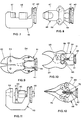
- Figure 1 is a perspective view of a basic unit according to the invention provided with a shearing head,
- Figure 2 is an enlarged longitudinal section view thereof,
- Figure 3 is an enlarged sectional partial view of the pump,
- Figure 4 is a detailed enlarged view of the head of the piston,
- Figure 5 is a plan view of the shearing head,
- Figure 6 is a plan view of a first embodiment of a bending head,
- Figure 7 is a lateral view thereof,
- Figure 8 is a plan view of a second embodiment of a bending head,
- Figure 9 is a plan view of a snips head with coplanar blades,
- Figure 10 is a partly fragmented plan view of a snips head having blades scissor-operable,
- Figure 11 is a lateral view of a punching head, and
- Figure 12 is a plan view of a divaricating head.
- As can be seen from the figures the portable operating apparatus according to the invention substantially comprises a
body 1 provided withhandle 2, and having at one end anelectrical motor 3 and at the other end aflange 4 supporting the heads. - The
body 1 comprises anupper tank 5 for the fluid, communicating with a cylindric hollow 6, in which apiston pump 7 is housed. - In particular the
pump 7 comprises a three-lobes 10 body having a middle cylindric hollow 8, at which cylindricradial seats 9 end up, foreseen in the threelobes 10. Inside eachcylindric seat 9, which is crossed by agroove 12 transversely made in thecorresponding lobe 10, an axially displaceablelittle piston 11 is housed. - At the outer end of each
cylindric seat 9, beyond thecorresponding groove 12,holes 13 are foreseen. Ducts 13 end up at theseholes 13 connecting theseat 9 with the front surface of the pump (at the right hand in figure 2). - The
ducts 14 are provided with non-return valves (not shown in the drawings) to allow the unidirectional flow of the fluid pumped by thepistons 11. - Each
piston 11 is kept with its inner end projecting inside the cylindric hollow 8 and is also elastically kept into touch with a commonannular element 15 having diameter less than the diameter of the hollow 8 and housed inside this. - An eccentric pin 16 bound to the shaft of the
motor 3, is engaged within theannular element 15. To said shaft also atraditional cooling fan 17 is applied. - Furthermore a
cylindric chamber 18 is foreseen inside thebody 1, coaxially with thepump 7. Within said chamber the head of apiston 19 is displaceable, having therod 20 which comes out from theflange 4. - In the
body 1, outwardly thecylindric chamber 18, alongitudinal duct 21 is foreseen, connecting thetank 5 with thechamber 18 downstream the head of thepiston 19 through a shortradial duct 22. - Furthermore in the
body 1, outwardly at thechamber 18, acylindric seat 23 is foreseen housing a safety-valve. This valve comprise a point-shaped stem 25, pushed by asolenoidal spring 26 to close aduct 28 connecting theseat 23 with thechamber 18 upstream the head of thepiston 19. - The elastic reaction of the
spring 26 is adjusted by abush 26 screwed in a corresponding threaded portion of theseat 23. - A short
radial duct 24, foreseen in thebody 1 outwardly thechamber 18, connects theseat 23 with thechamber 18 downstream the head of thepiston 19. - Furthermore in the rear wall of the
chamber 18,ducts 29 are foreseen, coaxially extending from theducts 14 of thepump 7. - Finally in the
body 1, outwardly at thechamber 18, afurther duct 30 is foreseen, connecting this chamber with thetank 5 through avalve 31, which in the illustrated embodiment is handly-actuable by the user. - The head of the
piston 19 is provided with a mushroom-shaped valve 32, having itshead 33 facing twopassing holes 34 made in the same head of thepiston 19. Asolenoidal spring 35 keeps elsatically spaced apart saidhead 33 from the head of thepiston 19. - A further
solenoidal spring 36 is foreseen around to therod 20 of thepiston 19. - The
flange 4 has the central hole, through which therod 20 passes, provided with a longitudinal groove guiding aspline 38 applied to saidrod 20, which therefore can axially be displaced but cannot rotate around its longitudinal axis. - The outer side surface of the
flange 4 is provided with aperimetric groove 39, to be engaged by a corresponding edge of aremovable ring 40. This ring consists of two portions hinged at one end and provided with mutual bond means at the other end. The other edge of thering 40 is engageable with acorresponding groove 41 foreseen in theflange 42 of the head of the tool, and in particular on the shearing head in figure 5. - The portable apparatus according to the invention operates as follows:
- in rest condition the
solenoidal spring 36 keeps the head of thepiston 19 adhering to the rear wall of thecylindric chamber 18, so that the head of thevalve 32 adheres to the head of thepiston 19 and closes theholes 34. - In this condition the
solenoidal spring 26 keeps thestem 25 of the safety-valve in closing theduct 28. When the user actuated atrigger 44 foreseen in thehandle 2 thus causing theelectrical motor 3 to start, the rotation of the eccentric 16 causes, through theannular element 15, the reciprocal movement of thepiston 11 inside therespective seats 9. In this way the oil which comes from thetank 5 and practically fills all the inner hollows of thepump 7, and in particular thegrooves 12, is pumped from thepistons 11 through theducts cylindric chamber 18. - The continuous flow of oil inside this
chamber 18 causes the displacement of thepiston 19 and the consequent outcoming of itsrod 20, which in this way can drive the operating head coupled to it. In the embodiment shown in Figures 1 and 5, a movable blade 45' cooperating with thefixed blade 45 of the shearinghead 43 is applied to therod 20 of thepiston 19. - Furthermore the oil pressure against the head of the
piston 19 keeps thehead 33 of the mushroom-shaped valve 32 adhering to the head of thepiston 19. - During the outcoming of the
rod 20, the oil downstream the head of thepiston 19 is discharged, through theducts tank 5. - When the
piston 19 has reached its front end-of-travel condition, and consequently the tool has completed its active stroke, the stem of thevalve 32 interacts with the front wall of thechamber 18 axially displacing backward thesame valve 32 and removing its head from the head of thepiston 19, thus opening theholes 34. In this way the oil further entering into thechamber 18 passes through theseholes 34 and returns, through theduct 21, into thetank 5. - At this moment the user, releasing the
gripper 44, halts theelectric motor 3, and stops the feeding of oil inside thechamber 18. Since theholes 34 are open during this phase, after a short time the pressures downstream and upstream the head of thepiston 19 become equal and the elastic reaction of thespring 36, previously compressed, prevails causing the return stroke of thepiston 19. - In the case in which, for example during the shearing of a very hard piece, the outcoming of the
piston 19 should be impeded, thus strongly incresaing the pressure inside thechamber 18, the safety-valve 25 intervenes. Indeed the high pressure upstream thepiston 19 prevails on the elastic reaction of thesolenoidal spring 26 and causes the back displacement of thestem 25 and the opening of theduct 28. - In this way the oil enters the
seat 23, passes through thebush 27 and enters thechamber 18, downstream the head of thepiston 19, returning into thetank 5 through theduct 21. - if the return stroke of the piston before reaching the front end-of-travel position is required, it is sufficient to stop the
motor 3 and to handly open thevalve 31. In this way the oil housed inside thechamber 18 can return into thetank 5 through theduct 30. - In order to use the portable apparatus according to the invention with a different operating head, the user disengages the portions of the
ring 40, takes away the shearinghead 43 and replaces it with another one fit to carry out the new function. - In the figures 6 and 7 a bending head is shown, to which a
semicylindric mould 47 is bound, complementary to a movableU-shaped counter-mould 48, actuated by therod 20 of thepiston 19. It is clear that, during the actuating of the apparatus and therefore during the advancement of the counter-mould 48 towards themould 47, the bending of a metal bar interplaced between them is caused. - In the figure 8 a second embodiment of a bending head is shown in which the
movable counter-mould 49 is provided with a pair ofrollers 50, allowing to carry out the soft bending of the metal bar, without any stretching. - In Figure 9 a
snips head 51 is shown havingcoplanar blades 52. These blades are articulated to twopins 53 and are kept in open condition by the elastic reaction of twosprings 54. Awedge 55 is placed between the arms of theblades 52, beyond their articulation pins 53. - While operating, the advancement of the
rod 20 causes the displacement of thewedge 55 and the divarication of the arms with the consequent rotation and closure of theblades 52. - Due to the
springs 54, which ensure the elastic return of the blades to the open condition when therod 20 goes back inside the operating unit, no connection is necessary between therod 20 and thewedge 55, but only a simple rest which makes easier and quicker the engagement between the head and the operating unit. - In Figure 10 a
snips head 56 is shown having theblades 57 scissors-actuable. - The
blades 57 are articulated to apin 58 and twopushers 60 are toggle-articulated to thearms 59 of said blades and to ablock 61, which is obliged to move along twolongitudinal holes 62 made in the body or thehead 56. While operating, the head of therod 20 is rested against theblock 61 which, owing to the outcoming of the rod, is axially displaced and causes the rotation to the close condition of theblades 57. - In Figure 11 a punching
head 63 is shown comprising a die 64 to be applied to theflange 4 of the operating unit, and aspindle 65 screwing thepunch 66 to the rod. Anextracter member 67 bound to thedie 64 holds the metal sheet placed between saiddie 64 and thepunch 66 during the return-stroke of this punch. - In Figure 12 a divaricating
head 68 is shown comprising a body to be applied to theflange 4 and a pair of divaricatingarms 70 articulated to thebody 6. Twosmaller arms 71 are furthermore articulated to thesearms 70 even articulated to each other and to an actuatingmiddle block 72, against which the end of therod 20 rests. A pair of traction-operating solenoidal springs 73 keep both the twoarms 70 in approached condition. In operating, the axial advancement of therod 20 causes the forward displacement of theblock 72 which, overcoming the elastic reaction of thesprings 73 pushes thearms 71 to divaricate the twoarms 70. - When the
rod 20 goes back, thesprings 73 bring thearm 70 in approached condition. - In the shown embodiment, it has been referred to an apparatus provided with a simple-acting cylinder, in which the active stroke of the
piston 19 occurs during the inlet of the oil inside thechamber 18, whereas the return stroke is obtained through the elastic reaction of thespring 36 compressed during the active stroke. - It is indeed foreseeable an embodiment with a double-acting cylinder, in which both the strokes are controlled by the oil.
- This embodiment, which is not shown in the drawings, obviously requires a suitable distribution system which selectively allows the feeding of the oil inside the
chamber 18 downstream and upstream thepiston 19, but all this is well known to the skilled man and therefore doesn't require any further information. - Obviously in the case of a double-acting cylinder it is not possible to keep the connection between the end of the
rod 20 and the corresponding portion of the operating head by a simple rest, but it is necessary to replace it with a steady connection, for example obtainable by screwing. - It is clear that in this case the springs, ensuring the elastic return to the rear condition of the movable parts of the operating heads, are not be necessary.
- In the shown embodiment a handly-
actuable valve 31 has been described, but it is also foreseeable an embodiment with an electro-valve controlled by thesame trigger 44 actuating theelectric motor 3. In this case, when the user stops themotor 3, whatever is the position of thepiston 9 coming out from the flange, theelectrovalve 31 intervenes and controls the discharge of the oil into thetank 5 allowing thepiston 19 to return to its rest position, even if the front end-of-travel condition has not been reached. - Finally the
motor 3 driving thepump 7 has been illustrated as an electric motor, but it could be of another kind, particularly an internal combustion one, advantageously usable in all the cases in which the electric energy is not available or usable.
Claims (17)
Priority Applications (1)
| Application Number | Priority Date | Filing Date | Title |
|---|---|---|---|
| AT86906314T ATE54868T1 (en) | 1985-10-18 | 1986-10-20 | PORTABLE POWER DEVICE WITH INTERCHANGEABLE HEADS. |
Applications Claiming Priority (2)
| Application Number | Priority Date | Filing Date | Title |
|---|---|---|---|
| IT8255185 | 1985-10-18 | ||
| IT82551/85A IT1187435B (en) | 1985-10-18 | 1985-10-18 | INTERCHANGEABLE HEAD BENDING SHEAR AND AUTOMATIC PRESSURE CONTROL |
Publications (2)
| Publication Number | Publication Date |
|---|---|
| EP0244450A1 EP0244450A1 (en) | 1987-11-11 |
| EP0244450B1 true EP0244450B1 (en) | 1990-07-25 |
Family
ID=11318724
Family Applications (2)
| Application Number | Title | Priority Date | Filing Date |
|---|---|---|---|
| EP86202028A Pending EP0235403A1 (en) | 1985-10-18 | 1986-10-20 | Portable operating apparatus with inter-changeable heads |
| EP86906314A Expired EP0244450B1 (en) | 1985-10-18 | 1986-10-20 | Portable operating apparatus with interchangeable heads |
Family Applications Before (1)
| Application Number | Title | Priority Date | Filing Date |
|---|---|---|---|
| EP86202028A Pending EP0235403A1 (en) | 1985-10-18 | 1986-10-20 | Portable operating apparatus with inter-changeable heads |
Country Status (6)
| Country | Link |
|---|---|
| EP (2) | EP0235403A1 (en) |
| AU (1) | AU6599586A (en) |
| DE (1) | DE3673010D1 (en) |
| ES (1) | ES2017645B3 (en) |
| IT (1) | IT1187435B (en) |
| WO (1) | WO1987002295A2 (en) |
Families Citing this family (2)
| Publication number | Priority date | Publication date | Assignee | Title |
|---|---|---|---|---|
| FR2677908B1 (en) * | 1991-06-20 | 1995-04-07 | Hydr Am | VERSATILE SELF-CONTAINED TOOL SUCH AS SHEARS / HYDRAULICALLY CONTROLLED SPREADERS. |
| EP1724043A1 (en) * | 2005-05-18 | 2006-11-22 | Gerd Friedrich Guenter Dr. Koennecker | Hydraulic shears or similar tools with a piston driven by a linear electric motor |
Family Cites Families (11)
| Publication number | Priority date | Publication date | Assignee | Title |
|---|---|---|---|---|
| US2241089A (en) * | 1940-01-18 | 1941-05-06 | Otto A Hampe | Pipe coupling clamp |
| US3073372A (en) * | 1957-10-30 | 1963-01-15 | Lang Ludwig | Apparatus for cold bending of tubular bodies and the like |
| CH384501A (en) * | 1959-09-26 | 1964-11-15 | Hydrodyn Ag | Multipurpose device |
| DE1627140C3 (en) * | 1963-06-22 | 1973-01-04 | Rudolf 7031 Holzgerlingen Bock | Hydraulic cutting machine, in particular for cutting structural steel. Eliminated from: 1502689 |
| DE2024890C3 (en) * | 1970-05-22 | 1978-11-16 | Rudolf 7031 Holzgerlingen Bock | Hydraulic shears, especially for cutting round steel bars |
| FR2199672A6 (en) * | 1972-09-19 | 1974-04-12 | Gravelais Rene | |
| US4193733A (en) * | 1978-05-17 | 1980-03-18 | Harnischfeger Corporation | Hydraulic excavator machine having self-contained electrohydraulic power units |
| FR2500344A1 (en) * | 1981-02-23 | 1982-08-27 | Parmentier Jean | Scissor-action jack-actuated sheet metal shears - has centre blade between pair of counter blades with fulcrum tied to jack case |
| DE8121716U1 (en) * | 1981-07-24 | 1981-11-19 | IHG Gleitlager GmbH, 7100 Heilbronn | Device for pressing in bearing bushes |
| GB2132298A (en) * | 1982-12-23 | 1984-07-04 | Dobson Park Ind | Pipe coupling |
| US4506445A (en) * | 1983-02-22 | 1985-03-26 | Hale Fire Pump Company | Rescue cutter tool |
-
1985
- 1985-10-18 IT IT82551/85A patent/IT1187435B/en active
-
1986
- 1986-10-20 EP EP86202028A patent/EP0235403A1/en active Pending
- 1986-10-20 EP EP86906314A patent/EP0244450B1/en not_active Expired
- 1986-10-20 ES ES86906314T patent/ES2017645B3/en not_active Expired - Lifetime
- 1986-10-20 AU AU65995/86A patent/AU6599586A/en not_active Abandoned
- 1986-10-20 WO PCT/EP1986/000596 patent/WO1987002295A2/en not_active Ceased
- 1986-10-20 DE DE8686906314T patent/DE3673010D1/en not_active Expired - Lifetime
Also Published As
| Publication number | Publication date |
|---|---|
| DE3673010D1 (en) | 1990-08-30 |
| IT8582551A0 (en) | 1985-10-18 |
| WO1987002295A3 (en) | 1987-06-04 |
| ES2017645B3 (en) | 1991-03-01 |
| IT1187435B (en) | 1987-12-23 |
| EP0244450A1 (en) | 1987-11-11 |
| AU6599586A (en) | 1987-05-05 |
| WO1987002295A2 (en) | 1987-04-23 |
| EP0235403A1 (en) | 1987-09-09 |
Similar Documents
| Publication | Publication Date | Title |
|---|---|---|
| US11833597B2 (en) | Hydraulic power tool | |
| US5282378A (en) | Fluid actuated, double acting machine for punching, cutting, bending or the like | |
| US6862793B2 (en) | Riveting device and method for riveting | |
| US5272811A (en) | Hydraulically controlled self-contained multifunctional tool such as shears/separator | |
| JPS6346069Y2 (en) | ||
| JP5066102B2 (en) | Hydraulic drive pressing device and fixing device pressing method | |
| AU2003214204B2 (en) | Portable hydraulic crimping tool | |
| US5233749A (en) | Hydraulic actuator | |
| US5476119A (en) | Hand held power operated shears | |
| US4283851A (en) | Scissor-type shear, especially a cable cutter | |
| US6367156B1 (en) | Blades for hand held power operated shears | |
| US4791726A (en) | Fluid operated shears | |
| EP0244450B1 (en) | Portable operating apparatus with interchangeable heads | |
| US5918370A (en) | Hand held power assisted shears | |
| US3059334A (en) | Power operated shear | |
| CS212265B2 (en) | Shears for the chipless separation of the profiled material sections | |
| JP2535526Y2 (en) | Portable hydraulic compressor | |
| EP0771253B1 (en) | Blades for hand-held power operated shears | |
| JP3003052U (en) | Portable shears | |
| US4475423A (en) | Shear for cutting rod-form material | |
| US20260085713A1 (en) | Hydraulic power tool | |
| EP4684839A1 (en) | Portable rescue equipment | |
| JP2805282B2 (en) | Shearing machine | |
| CN113329828A (en) | Device for punching and stamping plate-shaped workpieces | |
| EP1854566A1 (en) | Compound machine |
Legal Events
| Date | Code | Title | Description |
|---|---|---|---|
| PUAI | Public reference made under article 153(3) epc to a published international application that has entered the european phase |
Free format text: ORIGINAL CODE: 0009012 |
|
| 17P | Request for examination filed |
Effective date: 19870910 |
|
| AK | Designated contracting states |
Kind code of ref document: A1 Designated state(s): AT BE CH DE FR GB IT LI LU NL SE |
|
| 17Q | First examination report despatched |
Effective date: 19881019 |
|
| XX | Miscellaneous (additional remarks) |
Free format text: VERBUNDEN MIT 86202028.6/0235403 (EUROPAEISCHE ANMELDENUMMER/VEROEFFENTLICHUNGSNUMMER) DURCH ENTSCHEIDUNG VOM 08.03.89. |
|
| GRAA | (expected) grant |
Free format text: ORIGINAL CODE: 0009210 |
|
| AK | Designated contracting states |
Kind code of ref document: B1 Designated state(s): AT BE CH DE ES FR GB GR IT LI LU NL SE |
|
| PG25 | Lapsed in a contracting state [announced via postgrant information from national office to epo] |
Ref country code: SE Effective date: 19900725 Ref country code: NL Effective date: 19900725 Ref country code: GR Free format text: LAPSE BECAUSE OF FAILURE TO SUBMIT A TRANSLATION OF THE DESCRIPTION OR TO PAY THE FEE WITHIN THE PRESCRIBED TIME-LIMIT Effective date: 19900725 Ref country code: AT Effective date: 19900725 |
|
| REF | Corresponds to: |
Ref document number: 54868 Country of ref document: AT Date of ref document: 19900815 Kind code of ref document: T |
|
| XX | Miscellaneous (additional remarks) |
Free format text: VERBUNDEN MIT 86202028.6/0235403 (EUROPAEISCHE ANMELDENUMMER/VEROEFFENTLICHUNGSNUMMER) DURCH ENTSCHEIDUNG VOM 08.03.89. |
|
| REF | Corresponds to: |
Ref document number: 3673010 Country of ref document: DE Date of ref document: 19900830 |
|
| ITF | It: translation for a ep patent filed | ||
| PG25 | Lapsed in a contracting state [announced via postgrant information from national office to epo] |
Ref country code: LU Free format text: LAPSE BECAUSE OF NON-PAYMENT OF DUE FEES Effective date: 19901031 |
|
| ET | Fr: translation filed | ||
| NLV1 | Nl: lapsed or annulled due to failure to fulfill the requirements of art. 29p and 29m of the patents act | ||
| PLBE | No opposition filed within time limit |
Free format text: ORIGINAL CODE: 0009261 |
|
| STAA | Information on the status of an ep patent application or granted ep patent |
Free format text: STATUS: NO OPPOSITION FILED WITHIN TIME LIMIT |
|
| 26N | No opposition filed | ||
| PGFP | Annual fee paid to national office [announced via postgrant information from national office to epo] |
Ref country code: GB Payment date: 19911014 Year of fee payment: 6 |
|
| PGFP | Annual fee paid to national office [announced via postgrant information from national office to epo] |
Ref country code: CH Payment date: 19911016 Year of fee payment: 6 |
|
| PGFP | Annual fee paid to national office [announced via postgrant information from national office to epo] |
Ref country code: BE Payment date: 19911029 Year of fee payment: 6 |
|
| ITTA | It: last paid annual fee | ||
| PG25 | Lapsed in a contracting state [announced via postgrant information from national office to epo] |
Ref country code: GB Effective date: 19921020 |
|
| PG25 | Lapsed in a contracting state [announced via postgrant information from national office to epo] |
Ref country code: LI Effective date: 19921031 Ref country code: CH Effective date: 19921031 Ref country code: BE Effective date: 19921031 |
|
| BERE | Be: lapsed |
Owner name: CITTON GIANNI Effective date: 19921031 |
|
| GBPC | Gb: european patent ceased through non-payment of renewal fee |
Effective date: 19921020 |
|
| REG | Reference to a national code |
Ref country code: CH Ref legal event code: PL |
|
| PGFP | Annual fee paid to national office [announced via postgrant information from national office to epo] |
Ref country code: FR Payment date: 19980909 Year of fee payment: 13 |
|
| PGFP | Annual fee paid to national office [announced via postgrant information from national office to epo] |
Ref country code: ES Payment date: 19981001 Year of fee payment: 13 |
|
| PGFP | Annual fee paid to national office [announced via postgrant information from national office to epo] |
Ref country code: DE Payment date: 19981222 Year of fee payment: 13 |
|
| PG25 | Lapsed in a contracting state [announced via postgrant information from national office to epo] |
Ref country code: ES Free format text: LAPSE BECAUSE OF NON-PAYMENT OF DUE FEES Effective date: 19991021 |
|
| PG25 | Lapsed in a contracting state [announced via postgrant information from national office to epo] |
Ref country code: FR Free format text: LAPSE BECAUSE OF NON-PAYMENT OF DUE FEES Effective date: 20000630 |
|
| PG25 | Lapsed in a contracting state [announced via postgrant information from national office to epo] |
Ref country code: DE Free format text: LAPSE BECAUSE OF NON-PAYMENT OF DUE FEES Effective date: 20000801 |
|
| REG | Reference to a national code |
Ref country code: FR Ref legal event code: ST |
|
| REG | Reference to a national code |
Ref country code: ES Ref legal event code: FD2A Effective date: 20001113 |
|
| PGFP | Annual fee paid to national office [announced via postgrant information from national office to epo] |
Ref country code: IT Payment date: 20051027 Year of fee payment: 20 |