EP0244450B1 - Tragbares antriebsgerät mit auswechselbaren köpfen - Google Patents
Tragbares antriebsgerät mit auswechselbaren köpfen Download PDFInfo
- Publication number
- EP0244450B1 EP0244450B1 EP86906314A EP86906314A EP0244450B1 EP 0244450 B1 EP0244450 B1 EP 0244450B1 EP 86906314 A EP86906314 A EP 86906314A EP 86906314 A EP86906314 A EP 86906314A EP 0244450 B1 EP0244450 B1 EP 0244450B1
- Authority
- EP
- European Patent Office
- Prior art keywords
- head
- piston
- rod
- operating
- flange
- Prior art date
- Legal status (The legal status is an assumption and is not a legal conclusion. Google has not performed a legal analysis and makes no representation as to the accuracy of the status listed.)
- Expired
Links
Images


Classifications
-
- B—PERFORMING OPERATIONS; TRANSPORTING
- B25—HAND TOOLS; PORTABLE POWER-DRIVEN TOOLS; MANIPULATORS
- B25B—TOOLS OR BENCH DEVICES NOT OTHERWISE PROVIDED FOR, FOR FASTENING, CONNECTING, DISENGAGING, OR HOLDING
- B25B33/00—Hand tools not covered by any other group in this subclass
-
- B—PERFORMING OPERATIONS; TRANSPORTING
- B23—MACHINE TOOLS; METAL-WORKING NOT OTHERWISE PROVIDED FOR
- B23D—PLANING; SLOTTING; SHEARING; BROACHING; SAWING; FILING; SCRAPING; LIKE OPERATIONS FOR WORKING METAL BY REMOVING MATERIAL, NOT OTHERWISE PROVIDED FOR
- B23D15/00—Shearing machines or shearing devices cutting by blades which move parallel to themselves
- B23D15/12—Shearing machines or shearing devices cutting by blades which move parallel to themselves characterised by drives or gearings therefor
- B23D15/14—Shearing machines or shearing devices cutting by blades which move parallel to themselves characterised by drives or gearings therefor actuated by fluid or gas pressure
-
- B—PERFORMING OPERATIONS; TRANSPORTING
- B23—MACHINE TOOLS; METAL-WORKING NOT OTHERWISE PROVIDED FOR
- B23D—PLANING; SLOTTING; SHEARING; BROACHING; SAWING; FILING; SCRAPING; LIKE OPERATIONS FOR WORKING METAL BY REMOVING MATERIAL, NOT OTHERWISE PROVIDED FOR
- B23D31/00—Shearing machines or shearing devices covered by none or more than one of the groups B23D15/00 - B23D29/00; Combinations of shearing machines
Definitions
- the present invention relates to a portable operating apparatus with interchangeable heads.
- the known operating machines such as shears, bar benders, cutting machines and so on, consist of a unit comprising an electrical or internal combustion motor driving an oil pump which causes the displacement of a piston operating a tool.
- CH-A-384 501 describes a portable multi-role operating apparatus according to the preamble of claim 1.
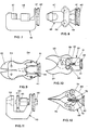
- the portable operating apparatus substantially comprises a body 1 provided with handle 2, and having at one end an electrical motor 3 and at the other end a flange 4 supporting the heads.
- the body 1 comprises an upper tank 5 for the fluid, communicating with a cylindric hollow 6, in which a piston pump 7 is housed.
- the pump 7 comprises a three- lobes 10 body having a middle cylindric hollow 8, at which cylindric radial seats 9 end up, foreseen in the three lobes 10.
- a middle cylindric hollow 8 at which cylindric radial seats 9 end up, foreseen in the three lobes 10.
- each cylindric seat 9 At the outer end of each cylindric seat 9, beyond the corresponding groove 12, holes 13 are foreseen. Ducts 13 end up at these holes 13 connecting the seat 9 with the front surface of the pump (at the right hand in figure 2).
- the ducts 14 are provided with non-return valves (not shown in the drawings) to allow the unidirectional flow of the fluid pumped by the pistons 11.
- Each piston 11 is kept with its inner end projecting inside the cylindric hollow 8 and is also elastically kept into touch with a common annular element 15 having diameter less than the diameter of the hollow 8 and housed inside this.
- An eccentric pin 16 bound to the shaft of the motor 3, is engaged within the annular element 15.
- a traditional cooling fan 17 is applied.
- a cylindric chamber 18 is foreseen inside the body 1, coaxially with the pump 7. Within said chamber the head of a piston 19 is displaceable, having the rod 20 which comes out from the flange 4.
- a longitudinal duct 21 is foreseen, connecting the tank 5 with the chamber 18 downstream the head of the piston 19 through a short radial duct 22.
- a cylindric seat 23 is foreseen housing a safety-valve.
- This valve comprise a point- shaped stem 25, pushed by a solenoidal spring 26 to close a duct 28 connecting the seat 23 with the chamber 18 upstream the head of the piston 19.
- the elastic reaction of the spring 26 is adjusted by a bush 26 screwed in a corresponding threaded portion of the seat 23.
- ducts 29 are foreseen, coaxially extending from the ducts 14 of the pump 7.
- a further duct 30 is foreseen, connecting this chamber with the tank 5 through a valve 31, which in the illustrated embodiment is handly-actuable by the user.
- the head of the piston 19 is provided with a mushroom-shaped valve 32, having its head 33 facing two passing holes 34 made in the same head of the piston 19.
- a solenoidal spring 35 keeps elsatically spaced apart said head 33 from the head of the piston 19.
- a further solenoidal spring 36 is foreseen around to the rod 20 of the piston 19.
- the flange 4 has the central hole, through which the rod 20 passes, provided with a longitudinal groove guiding a spline 38 applied to said rod 20, which therefore can axially be displaced but cannot rotate around its longitudinal axis.
- the outer side surface of the flange 4 is provided with a perimetric groove 39, to be engaged by a corresponding edge of a removable ring 40.
- This ring consists of two portions hinged at one end and provided with mutual bond means at the other end.
- the other edge of the ring 40 is engageable with a corresponding groove 41 foreseen in the flange 42 of the head of the tool, and in particular on the shearing head in figure 5.
- the portable apparatus according to the invention operates as follows:
- the solenoidal spring 36 keeps the head of the piston 19 adhering to the rear wall of the cylindric chamber 18, so that the head of the valve 32 adheres to the head of the piston 19 and closes the holes 34.
- the stem of the valve 32 interacts with the front wall of the chamber 18 axially displacing backward the same valve 32 and removing its head from the head of the piston 19, thus opening the holes 34. In this way the oil further entering into the chamber 18 passes through these holes 34 and returns, through the duct 21, into the tank 5.
- the user disengages the portions of the ring 40, takes away the shearing head 43 and replaces it with another one fit to carry out the new function.
- a bending head is shown, to which a semicylindric mould 47 is bound, complementary to a movable U-shaped counter-mould 48, actuated by the rod 20 of the piston 19. It is clear that, during the actuating of the apparatus and therefore during the advancement of the counter-mould 48 towards the mould 47, the bending of a metal bar interplaced between them is caused.
- FIG 8 a second embodiment of a bending head is shown in which the movable counter-mould 49 is provided with a pair of rollers 50, allowing to carry out the soft bending of the metal bar, without any stretching.
- a snips head 51 is shown having coplanar blades 52. These blades are articulated to two pins 53 and are kept in open condition by the elastic reaction of two springs 54. A wedge 55 is placed between the arms of the blades 52, beyond their articulation pins 53.
- a snips head 56 is shown having the blades 57 scissors-actuable.
- the blades 57 are articulated to a pin 58 and two pushers 60 are toggle-articulated to the arms 59 of said blades and to a block 61, which is obliged to move along two longitudinal holes 62 made in the body or the head 56. While operating, the head of the rod 20 is rested against the block 61 which, owing to the outcoming of the rod, is axially displaced and causes the rotation to the close condition of the blades 57.
- a punching head 63 comprising a die 64 to be applied to the flange 4 of the operating unit, and a spindle 65 screwing the punch 66 to the rod.
- An extracter member 67 bound to the die 64 holds the metal sheet placed between said die 64 and the punch 66 during the return-stroke of this punch.
- a divaricating head 68 comprising a body to be applied to the flange 4 and a pair of divaricating arms 70 articulated to the body 6.
- Two smaller arms 71 are furthermore articulated to these arms 70 even articulated to each other and to an actuating middle block 72, against which the end of the rod 20 rests.
- a pair of traction-operating solenoidal springs 73 keep both the two arms 70 in approached condition. In operating, the axial advancement of the rod 20 causes the forward displacement of the block 72 which, overcoming the elastic reaction of the springs 73 pushes the arms 71 to divaricate the two arms 70.
- a handly-actuable valve 31 has been described, but it is also foreseeable an embodiment with an electro-valve controlled by the same trigger 44 actuating the electric motor 3.
- the electrovalve 31 intervenes and controls the discharge of the oil into the tank 5 allowing the piston 19 to return to its rest position, even if the front end-of-travel condition has not been reached.
- motor 3 driving the pump 7 has been illustrated as an electric motor, but it could be of another kind, particularly an internal combustion one, advantageously usable in all the cases in which the electric energy is not available or usable.
Landscapes
- Engineering & Computer Science (AREA)
- Mechanical Engineering (AREA)
- Actuator (AREA)
- Fluid-Pressure Circuits (AREA)
- Shearing Machines (AREA)
- Reciprocating Pumps (AREA)
Claims (17)
Priority Applications (1)
| Application Number | Priority Date | Filing Date | Title |
|---|---|---|---|
| AT86906314T ATE54868T1 (de) | 1985-10-18 | 1986-10-20 | Tragbares antriebsgeraet mit auswechselbaren koepfen. |
Applications Claiming Priority (2)
| Application Number | Priority Date | Filing Date | Title |
|---|---|---|---|
| IT8255185 | 1985-10-18 | ||
| IT82551/85A IT1187435B (it) | 1985-10-18 | 1985-10-18 | Cesoia piegatrice a teste intercambiabili e controllo automatico della pressione |
Publications (2)
| Publication Number | Publication Date |
|---|---|
| EP0244450A1 EP0244450A1 (de) | 1987-11-11 |
| EP0244450B1 true EP0244450B1 (de) | 1990-07-25 |
Family
ID=11318724
Family Applications (2)
| Application Number | Title | Priority Date | Filing Date |
|---|---|---|---|
| EP86202028A Pending EP0235403A1 (de) | 1985-10-18 | 1986-10-20 | Tragbares Antriebsgerät mit auswechselbaren Köpfen |
| EP86906314A Expired EP0244450B1 (de) | 1985-10-18 | 1986-10-20 | Tragbares antriebsgerät mit auswechselbaren köpfen |
Family Applications Before (1)
| Application Number | Title | Priority Date | Filing Date |
|---|---|---|---|
| EP86202028A Pending EP0235403A1 (de) | 1985-10-18 | 1986-10-20 | Tragbares Antriebsgerät mit auswechselbaren Köpfen |
Country Status (6)
| Country | Link |
|---|---|
| EP (2) | EP0235403A1 (de) |
| AU (1) | AU6599586A (de) |
| DE (1) | DE3673010D1 (de) |
| ES (1) | ES2017645B3 (de) |
| IT (1) | IT1187435B (de) |
| WO (1) | WO1987002295A2 (de) |
Families Citing this family (2)
| Publication number | Priority date | Publication date | Assignee | Title |
|---|---|---|---|---|
| FR2677908B1 (fr) * | 1991-06-20 | 1995-04-07 | Hydr Am | Outil autonome polyvalent tel que cisaille/ecarteur a commande hydraulique. |
| EP1724043A1 (de) * | 2005-05-18 | 2006-11-22 | Gerd Friedrich Guenter Dr. Koennecker | Hydraulische Schere oder ähnliches Werkzeug mit einem durch einem elektrischen Linearmotor angetriebenen Kolben |
Family Cites Families (11)
| Publication number | Priority date | Publication date | Assignee | Title |
|---|---|---|---|---|
| US2241089A (en) * | 1940-01-18 | 1941-05-06 | Otto A Hampe | Pipe coupling clamp |
| US3073372A (en) * | 1957-10-30 | 1963-01-15 | Lang Ludwig | Apparatus for cold bending of tubular bodies and the like |
| CH384501A (de) * | 1959-09-26 | 1964-11-15 | Hydrodyn Ag | Mehrzweckgerät |
| DE1627140C3 (de) * | 1963-06-22 | 1973-01-04 | Rudolf 7031 Holzgerlingen Bock | Hydraulische Schneidemaschine, insbesondere zum Schneiden von Baustahl. Ausscheidung aus: 1502689 |
| DE2024890C3 (de) * | 1970-05-22 | 1978-11-16 | Rudolf 7031 Holzgerlingen Bock | Hydraulische Schere, insbesondere zum Schneiden von Rundstahlstäben |
| FR2199672A6 (de) * | 1972-09-19 | 1974-04-12 | Gravelais Rene | |
| US4193733A (en) * | 1978-05-17 | 1980-03-18 | Harnischfeger Corporation | Hydraulic excavator machine having self-contained electrohydraulic power units |
| FR2500344A1 (fr) * | 1981-02-23 | 1982-08-27 | Parmentier Jean | Perfectionnements apportes aux cisailles hydrauliques |
| DE8121716U1 (de) * | 1981-07-24 | 1981-11-19 | IHG Gleitlager GmbH, 7100 Heilbronn | Gerät zum Einpressen von Lagerbuchsen |
| GB2132298A (en) * | 1982-12-23 | 1984-07-04 | Dobson Park Ind | Pipe coupling |
| US4506445A (en) * | 1983-02-22 | 1985-03-26 | Hale Fire Pump Company | Rescue cutter tool |
-
1985
- 1985-10-18 IT IT82551/85A patent/IT1187435B/it active
-
1986
- 1986-10-20 EP EP86202028A patent/EP0235403A1/de active Pending
- 1986-10-20 WO PCT/EP1986/000596 patent/WO1987002295A2/en not_active Ceased
- 1986-10-20 DE DE8686906314T patent/DE3673010D1/de not_active Expired - Lifetime
- 1986-10-20 ES ES86906314T patent/ES2017645B3/es not_active Expired - Lifetime
- 1986-10-20 AU AU65995/86A patent/AU6599586A/en not_active Abandoned
- 1986-10-20 EP EP86906314A patent/EP0244450B1/de not_active Expired
Also Published As
| Publication number | Publication date |
|---|---|
| DE3673010D1 (de) | 1990-08-30 |
| IT1187435B (it) | 1987-12-23 |
| IT8582551A0 (it) | 1985-10-18 |
| ES2017645B3 (es) | 1991-03-01 |
| WO1987002295A2 (en) | 1987-04-23 |
| AU6599586A (en) | 1987-05-05 |
| WO1987002295A3 (en) | 1987-06-04 |
| EP0244450A1 (de) | 1987-11-11 |
| EP0235403A1 (de) | 1987-09-09 |
Similar Documents
| Publication | Publication Date | Title |
|---|---|---|
| US5282378A (en) | Fluid actuated, double acting machine for punching, cutting, bending or the like | |
| US5272811A (en) | Hydraulically controlled self-contained multifunctional tool such as shears/separator | |
| JPS6346069Y2 (de) | ||
| JP5066102B2 (ja) | 油圧駆動押圧装置及び固定具押圧方法 | |
| AU2003214204B2 (en) | Portable hydraulic crimping tool | |
| US5476119A (en) | Hand held power operated shears | |
| US4283851A (en) | Scissor-type shear, especially a cable cutter | |
| US20020148089A1 (en) | Riveting device and method for riveting | |
| US6367156B1 (en) | Blades for hand held power operated shears | |
| MXPA03002038A (es) | Herramienta de instalacion para instalar sujetadores roscados de tipo estampado. | |
| EP0244450B1 (de) | Tragbares antriebsgerät mit auswechselbaren köpfen | |
| US5150644A (en) | Release valve mechanism in a fluid operated linear actuator for a portable cutter or the like | |
| US5918370A (en) | Hand held power assisted shears | |
| US3059334A (en) | Power operated shear | |
| CS212265B2 (en) | Shears for the chipless separation of the profiled material sections | |
| JP2535526Y2 (ja) | 携帯用油圧式圧縮機 | |
| EP0771253B1 (de) | Schneidklingen für tragbare motorscheren | |
| JP3003052U (ja) | 携帯用剪断機 | |
| US4475423A (en) | Shear for cutting rod-form material | |
| EP4684839A1 (de) | Tragbare rettungsausrüstung | |
| JP2805282B2 (ja) | 剪断機 | |
| CN113329828A (zh) | 用于冲制和冲压板状工件的装置 | |
| EP1854566A1 (de) | Werkzeugmaschine | |
| JP2805276B2 (ja) | 携帯用棒鋼カッター | |
| JP4901291B2 (ja) | 油圧駆動装置及び同装置を備えた挟み処理装置 |
Legal Events
| Date | Code | Title | Description |
|---|---|---|---|
| PUAI | Public reference made under article 153(3) epc to a published international application that has entered the european phase |
Free format text: ORIGINAL CODE: 0009012 |
|
| 17P | Request for examination filed |
Effective date: 19870910 |
|
| AK | Designated contracting states |
Kind code of ref document: A1 Designated state(s): AT BE CH DE FR GB IT LI LU NL SE |
|
| 17Q | First examination report despatched |
Effective date: 19881019 |
|
| XX | Miscellaneous (additional remarks) |
Free format text: VERBUNDEN MIT 86202028.6/0235403 (EUROPAEISCHE ANMELDENUMMER/VEROEFFENTLICHUNGSNUMMER) DURCH ENTSCHEIDUNG VOM 08.03.89. |
|
| GRAA | (expected) grant |
Free format text: ORIGINAL CODE: 0009210 |
|
| AK | Designated contracting states |
Kind code of ref document: B1 Designated state(s): AT BE CH DE ES FR GB GR IT LI LU NL SE |
|
| PG25 | Lapsed in a contracting state [announced via postgrant information from national office to epo] |
Ref country code: SE Effective date: 19900725 Ref country code: NL Effective date: 19900725 Ref country code: GR Free format text: LAPSE BECAUSE OF FAILURE TO SUBMIT A TRANSLATION OF THE DESCRIPTION OR TO PAY THE FEE WITHIN THE PRESCRIBED TIME-LIMIT Effective date: 19900725 Ref country code: AT Effective date: 19900725 |
|
| REF | Corresponds to: |
Ref document number: 54868 Country of ref document: AT Date of ref document: 19900815 Kind code of ref document: T |
|
| XX | Miscellaneous (additional remarks) |
Free format text: VERBUNDEN MIT 86202028.6/0235403 (EUROPAEISCHE ANMELDENUMMER/VEROEFFENTLICHUNGSNUMMER) DURCH ENTSCHEIDUNG VOM 08.03.89. |
|
| REF | Corresponds to: |
Ref document number: 3673010 Country of ref document: DE Date of ref document: 19900830 |
|
| ITF | It: translation for a ep patent filed | ||
| PG25 | Lapsed in a contracting state [announced via postgrant information from national office to epo] |
Ref country code: LU Free format text: LAPSE BECAUSE OF NON-PAYMENT OF DUE FEES Effective date: 19901031 |
|
| ET | Fr: translation filed | ||
| NLV1 | Nl: lapsed or annulled due to failure to fulfill the requirements of art. 29p and 29m of the patents act | ||
| PLBE | No opposition filed within time limit |
Free format text: ORIGINAL CODE: 0009261 |
|
| STAA | Information on the status of an ep patent application or granted ep patent |
Free format text: STATUS: NO OPPOSITION FILED WITHIN TIME LIMIT |
|
| 26N | No opposition filed | ||
| PGFP | Annual fee paid to national office [announced via postgrant information from national office to epo] |
Ref country code: GB Payment date: 19911014 Year of fee payment: 6 |
|
| PGFP | Annual fee paid to national office [announced via postgrant information from national office to epo] |
Ref country code: CH Payment date: 19911016 Year of fee payment: 6 |
|
| PGFP | Annual fee paid to national office [announced via postgrant information from national office to epo] |
Ref country code: BE Payment date: 19911029 Year of fee payment: 6 |
|
| ITTA | It: last paid annual fee | ||
| PG25 | Lapsed in a contracting state [announced via postgrant information from national office to epo] |
Ref country code: GB Effective date: 19921020 |
|
| PG25 | Lapsed in a contracting state [announced via postgrant information from national office to epo] |
Ref country code: LI Effective date: 19921031 Ref country code: CH Effective date: 19921031 Ref country code: BE Effective date: 19921031 |
|
| BERE | Be: lapsed |
Owner name: CITTON GIANNI Effective date: 19921031 |
|
| GBPC | Gb: european patent ceased through non-payment of renewal fee |
Effective date: 19921020 |
|
| REG | Reference to a national code |
Ref country code: CH Ref legal event code: PL |
|
| PGFP | Annual fee paid to national office [announced via postgrant information from national office to epo] |
Ref country code: FR Payment date: 19980909 Year of fee payment: 13 |
|
| PGFP | Annual fee paid to national office [announced via postgrant information from national office to epo] |
Ref country code: ES Payment date: 19981001 Year of fee payment: 13 |
|
| PGFP | Annual fee paid to national office [announced via postgrant information from national office to epo] |
Ref country code: DE Payment date: 19981222 Year of fee payment: 13 |
|
| PG25 | Lapsed in a contracting state [announced via postgrant information from national office to epo] |
Ref country code: ES Free format text: LAPSE BECAUSE OF NON-PAYMENT OF DUE FEES Effective date: 19991021 |
|
| PG25 | Lapsed in a contracting state [announced via postgrant information from national office to epo] |
Ref country code: FR Free format text: LAPSE BECAUSE OF NON-PAYMENT OF DUE FEES Effective date: 20000630 |
|
| PG25 | Lapsed in a contracting state [announced via postgrant information from national office to epo] |
Ref country code: DE Free format text: LAPSE BECAUSE OF NON-PAYMENT OF DUE FEES Effective date: 20000801 |
|
| REG | Reference to a national code |
Ref country code: FR Ref legal event code: ST |
|
| REG | Reference to a national code |
Ref country code: ES Ref legal event code: FD2A Effective date: 20001113 |
|
| PGFP | Annual fee paid to national office [announced via postgrant information from national office to epo] |
Ref country code: IT Payment date: 20051027 Year of fee payment: 20 |