EP0552251B2 - Bilderzeugung/aufzeichnung durch verbesserte abtragungs-übertragung - Google Patents
Bilderzeugung/aufzeichnung durch verbesserte abtragungs-übertragung Download PDFInfo
- Publication number
- EP0552251B2 EP0552251B2 EP91918702A EP91918702A EP0552251B2 EP 0552251 B2 EP0552251 B2 EP 0552251B2 EP 91918702 A EP91918702 A EP 91918702A EP 91918702 A EP91918702 A EP 91918702A EP 0552251 B2 EP0552251 B2 EP 0552251B2
- Authority
- EP
- European Patent Office
- Prior art keywords
- imaging
- radiation
- topcoat
- release layer
- transfer
- Prior art date
- Legal status (The legal status is an assumption and is not a legal conclusion. Google has not performed a legal analysis and makes no representation as to the accuracy of the status listed.)
- Expired - Lifetime
Links
Images

Classifications
-
- B—PERFORMING OPERATIONS; TRANSPORTING
- B41—PRINTING; LINING MACHINES; TYPEWRITERS; STAMPS
- B41M—PRINTING, DUPLICATING, MARKING, OR COPYING PROCESSES; COLOUR PRINTING
- B41M5/00—Duplicating or marking methods; Sheet materials for use therein
- B41M5/26—Thermography ; Marking by high energetic means, e.g. laser otherwise than by burning, and characterised by the material used
- B41M5/40—Thermography ; Marking by high energetic means, e.g. laser otherwise than by burning, and characterised by the material used characterised by the base backcoat, intermediate, or covering layers, e.g. for thermal transfer dye-donor or dye-receiver sheets; Heat, radiation filtering or absorbing means or layers; combined with other image registration layers or compositions; Special originals for reproduction by thermography
- B41M5/46—Thermography ; Marking by high energetic means, e.g. laser otherwise than by burning, and characterised by the material used characterised by the base backcoat, intermediate, or covering layers, e.g. for thermal transfer dye-donor or dye-receiver sheets; Heat, radiation filtering or absorbing means or layers; combined with other image registration layers or compositions; Special originals for reproduction by thermography characterised by the light-to-heat converting means; characterised by the heat or radiation filtering or absorbing means or layers
- B41M5/465—Infra-red radiation-absorbing materials, e.g. dyes, metals, silicates, C black
-
- B—PERFORMING OPERATIONS; TRANSPORTING
- B41—PRINTING; LINING MACHINES; TYPEWRITERS; STAMPS
- B41M—PRINTING, DUPLICATING, MARKING, OR COPYING PROCESSES; COLOUR PRINTING
- B41M5/00—Duplicating or marking methods; Sheet materials for use therein
- B41M5/26—Thermography ; Marking by high energetic means, e.g. laser otherwise than by burning, and characterised by the material used
- B41M5/382—Contact thermal transfer or sublimation processes
- B41M5/38207—Contact thermal transfer or sublimation processes characterised by aspects not provided for in groups B41M5/385 - B41M5/395
- B41M5/38214—Structural details, e.g. multilayer systems
-
- G—PHYSICS
- G01—MEASURING; TESTING
- G01D—MEASURING NOT SPECIALLY ADAPTED FOR A SPECIFIC VARIABLE; ARRANGEMENTS FOR MEASURING TWO OR MORE VARIABLES NOT COVERED IN A SINGLE OTHER SUBCLASS; TARIFF METERING APPARATUS; MEASURING OR TESTING NOT OTHERWISE PROVIDED FOR
- G01D15/00—Component parts of recorders for measuring arrangements not specially adapted for a specific variable
- G01D15/10—Heated recording elements acting on heatsensitive layers
-
- G—PHYSICS
- G03—PHOTOGRAPHY; CINEMATOGRAPHY; ANALOGOUS TECHNIQUES USING WAVES OTHER THAN OPTICAL WAVES; ELECTROGRAPHY; HOLOGRAPHY
- G03F—PHOTOMECHANICAL PRODUCTION OF TEXTURED OR PATTERNED SURFACES, e.g. FOR PRINTING, FOR PROCESSING OF SEMICONDUCTOR DEVICES; MATERIALS THEREFOR; ORIGINALS THEREFOR; APPARATUS SPECIALLY ADAPTED THEREFOR
- G03F3/00—Colour separation; Correction of tonal value
- G03F3/10—Checking the colour or tonal value of separation negatives or positives
- G03F3/108—Checking the colour or tonal value of separation negatives or positives using a non-impact printing method, e.g. ink jet, using duplicating or marking methods covered by B41M5/00, e.g. by ablation or by thermographic means
-
- B—PERFORMING OPERATIONS; TRANSPORTING
- B41—PRINTING; LINING MACHINES; TYPEWRITERS; STAMPS
- B41M—PRINTING, DUPLICATING, MARKING, OR COPYING PROCESSES; COLOUR PRINTING
- B41M5/00—Duplicating or marking methods; Sheet materials for use therein
- B41M5/24—Ablative recording, e.g. by burning marks; Spark recording
-
- B—PERFORMING OPERATIONS; TRANSPORTING
- B41—PRINTING; LINING MACHINES; TYPEWRITERS; STAMPS
- B41M—PRINTING, DUPLICATING, MARKING, OR COPYING PROCESSES; COLOUR PRINTING
- B41M5/00—Duplicating or marking methods; Sheet materials for use therein
- B41M5/26—Thermography ; Marking by high energetic means, e.g. laser otherwise than by burning, and characterised by the material used
- B41M5/382—Contact thermal transfer or sublimation processes
- B41M5/38257—Contact thermal transfer or sublimation processes characterised by the use of an intermediate receptor
-
- B—PERFORMING OPERATIONS; TRANSPORTING
- B41—PRINTING; LINING MACHINES; TYPEWRITERS; STAMPS
- B41M—PRINTING, DUPLICATING, MARKING, OR COPYING PROCESSES; COLOUR PRINTING
- B41M5/00—Duplicating or marking methods; Sheet materials for use therein
- B41M5/26—Thermography ; Marking by high energetic means, e.g. laser otherwise than by burning, and characterised by the material used
- B41M5/382—Contact thermal transfer or sublimation processes
- B41M5/385—Contact thermal transfer or sublimation processes characterised by the transferable dyes or pigments
- B41M5/3854—Dyes containing one or more acyclic carbon-to-carbon double bonds, e.g., di- or tri-cyanovinyl, methine
-
- B—PERFORMING OPERATIONS; TRANSPORTING
- B41—PRINTING; LINING MACHINES; TYPEWRITERS; STAMPS
- B41M—PRINTING, DUPLICATING, MARKING, OR COPYING PROCESSES; COLOUR PRINTING
- B41M5/00—Duplicating or marking methods; Sheet materials for use therein
- B41M5/26—Thermography ; Marking by high energetic means, e.g. laser otherwise than by burning, and characterised by the material used
- B41M5/40—Thermography ; Marking by high energetic means, e.g. laser otherwise than by burning, and characterised by the material used characterised by the base backcoat, intermediate, or covering layers, e.g. for thermal transfer dye-donor or dye-receiver sheets; Heat, radiation filtering or absorbing means or layers; combined with other image registration layers or compositions; Special originals for reproduction by thermography
- B41M5/42—Intermediate, backcoat, or covering layers
- B41M5/426—Intermediate, backcoat, or covering layers characterised by inorganic compounds, e.g. metals, metal salts, metal complexes
-
- B—PERFORMING OPERATIONS; TRANSPORTING
- B41—PRINTING; LINING MACHINES; TYPEWRITERS; STAMPS
- B41M—PRINTING, DUPLICATING, MARKING, OR COPYING PROCESSES; COLOUR PRINTING
- B41M7/00—After-treatment of prints, e.g. heating, irradiating, setting of the ink, protection of the printed stock
- B41M7/0027—After-treatment of prints, e.g. heating, irradiating, setting of the ink, protection of the printed stock using protective coatings or layers by lamination or by fusion of the coatings or layers
-
- H—ELECTRICITY
- H05—ELECTRIC TECHNIQUES NOT OTHERWISE PROVIDED FOR
- H05K—PRINTED CIRCUITS; CASINGS OR CONSTRUCTIONAL DETAILS OF ELECTRIC APPARATUS; MANUFACTURE OF ASSEMBLAGES OF ELECTRICAL COMPONENTS
- H05K3/00—Apparatus or processes for manufacturing printed circuits
- H05K3/0073—Masks not provided for in groups H05K3/02 - H05K3/46, e.g. for photomechanical production of patterned surfaces
- H05K3/0079—Masks not provided for in groups H05K3/02 - H05K3/46, e.g. for photomechanical production of patterned surfaces characterised by the method of application or removal of the mask
-
- Y—GENERAL TAGGING OF NEW TECHNOLOGICAL DEVELOPMENTS; GENERAL TAGGING OF CROSS-SECTIONAL TECHNOLOGIES SPANNING OVER SEVERAL SECTIONS OF THE IPC; TECHNICAL SUBJECTS COVERED BY FORMER USPC CROSS-REFERENCE ART COLLECTIONS [XRACs] AND DIGESTS
- Y10—TECHNICAL SUBJECTS COVERED BY FORMER USPC
- Y10S—TECHNICAL SUBJECTS COVERED BY FORMER USPC CROSS-REFERENCE ART COLLECTIONS [XRACs] AND DIGESTS
- Y10S430/00—Radiation imagery chemistry: process, composition, or product thereof
- Y10S430/146—Laser beam
-
- Y—GENERAL TAGGING OF NEW TECHNOLOGICAL DEVELOPMENTS; GENERAL TAGGING OF CROSS-SECTIONAL TECHNOLOGIES SPANNING OVER SEVERAL SECTIONS OF THE IPC; TECHNICAL SUBJECTS COVERED BY FORMER USPC CROSS-REFERENCE ART COLLECTIONS [XRACs] AND DIGESTS
- Y10—TECHNICAL SUBJECTS COVERED BY FORMER USPC
- Y10S—TECHNICAL SUBJECTS COVERED BY FORMER USPC CROSS-REFERENCE ART COLLECTIONS [XRACs] AND DIGESTS
- Y10S430/00—Radiation imagery chemistry: process, composition, or product thereof
- Y10S430/165—Thermal imaging composition
Definitions
- the present invention relates a method for transferring a contrasting pattern of intelligence from an ablation-transfer imaging media to a receptor element in contiguous registration therewith.
- the phenomenon of, e.g., laser-induced ablation-transfer imaging is generically known to this art and is believed to entail both complex non-equilibrium physical and chemical mechanisms. Indeed, such laser-induced ablation-transfer is thought to be effected by the rapid and transient accumulation of pressure beneath and/or within a mass transfer layer initiated by imagewise irradiation. Transient pressure accumulation can be attributed to one or more of the following factors: rapid gas formation via chemical decomposition and/or rapid heating of trapped gases, evaporation, photo and thermal expansion, ionization and/or by propagation of a shockwave. The force produced by the release of such pressure is sufficient to cause transfer of the imaging layer to an adjacent receptor element. The force is preferably sufficient to effect the complete transfer of the exposed area of an entire layer rather than the partial or selective-transfer of components thereof.
- ablation transfer differs from the known material transfer techniques such as, for example, thermal melt transfer and dye sublimation/dye diffusion thermal transfer (D2T2).
- D2T2 dye sublimation/dye diffusion thermal transfer
- the donor sheet includes a material which strongly absorbs at the wavelength of the laser emission.
- this absorbing material converts the laser light to thermal energy and transfers the heat to a colorant transfer layer which also includes a binder, fusible compound, etc., thereby raising its temperature above its melting point to effect its transfer onto an adjacent receptor sheet.
- a specially treated or special receptor sheet e.g., coated or porous
- the aforementioned JP-A-62-140 884 describes a laser recording device, the focus of which is a composite transfer sheet including a base layer of plastic film, a middle layer containing substances that absorb laser light and convert it to heat and a transfer layer topcoat, the primary component of which is a colorant, as well as a receiver sheet to which images are transferred under the influence of the laser.
- the colorant transfer layer and/or top receiver sheet layer necessarily includes a heat-fusible phenolic, naphtholic, aromatic carboxylic acid or fatty acid amide compound.
- the plastic film base layer is thus coated with a substance that absorbs laser light and converts it to heat and is not transferred. This heat melts and transfers the image from the transfer layer to the receiver sheet and is said to provide a high-resolution and high-density image thereon.
- Laser-induced recording based on the removal or displacement of material from the exposed area is also known to the recording art.
- these applications do not require transfer of the material from one substrate to another.
- laser-induced recording has been used, for example, in optical disk writing with near infrared (IR) lasers typically emitting at wavelengths ranging from 760 nm to 850 nm employed as the writing source.
- IR near infrared
- polymeric binders are typically non-absorbent in the near infrared region (760 nm to 2500 nm)
- infrared absorbers i.e., sensitizers, are added to the substrate to absorb the laser radiation. This arrangement allows the laser radiation absorbed by the sensitizer to be converted to heat which causes pit formation.
- Prior art laser-induced ablative transfer imaging processes are limited to the use of large amounts of a black body absorber such as graphite or carbon black to transfer a black image.
- a black body absorber such as graphite or carbon black
- the black body absorbers employed are highly absorbent in the visible and ultraviolet (UV) as well as in the infrared region, the resulting transferred image is always black due to the presence of the absorber
- Such ablative transfer imaging based on black body absorbers is therefore entirely ineffective and wholly unsuited for many applications, e.g., color transfer imaging, color proofing, security printing, etc.
- US-A-3 962 513 describes a laser-ablative transfer medium intended for use in producing a planographic printing plate.
- This medium has a laser energy absorbing layer, which comprises particles of carbon black and a self-oxidizing binder, and which is separate from a topcoat comprising an ink-receptive resin.
- the topcoat Upon absorption of laser - radiation by the energy absorbing layer, the topcoat is ablatively transferred to a lithographic surface.
- at least a portion of the energy absorbing layer will be transferred with the topcoat;
- This invention provides an ablation-transfer imaging method, is similar to that described in the aforementioned US-A-3 962 513 in that it comprises a radiation-absorbing "dynamic release layer" which is separate from a topcoat containing a colorant.
- the dynamic release layer uses a non-black body radiation absorber, and the topcoat contains a non-black body contrast imaging material, so that colored images, free from black body absorbers, can be produced.
- this invention provides a method for transferring a contrasting pattern of intelligence from an ablation-transfer imaging medium to a receptor element in contiguous registration therewith, the medium comprising:
- the present ablation-transfer imaging medium necessarily includes at least one dynamic release layer (ii) intermediate the support substrate (i) and the imaging radiation-ablative carrier topcoat (iii).
- dynamic release layer is intended an intermediate layer that must interact with the imaging radiation to effect imagewise ablative transfer of at least the carrier topcoat onto a receptor element at an energy/fluence less than would be required in the absence thereof.
- the dynamic release layer is believed to release the carrier topcoat by effectively eliminating the adhesive forces that bond or consolidate the carrier topcoat with the support substrate.
- additional propulsion is simultaneously provided by the interaction of the imaging radiation therewith, e.g., by ablation of the dynamic release layer itself, thus further facilitating the imagewise ablative transfer of the entire carrier topcoat to a receptor element.
- the dynamic release layer is at least one layer of any organic or inorganic material, or combination thereof, that absorbs at least a fraction of the imaging radiation sufficient to diminish the adhesion (in the imagewise exposed areas) between said at least one DRL and the support substrate, the DRL(s) and the carrier topcoat, or both.
- Such material can be intrinsically absorbing, or sensitized to absorb wavelengths of the imaging radiation.
- the DRL(s) are intrinsically or inherently absorbing of the imaging radiation, highly absorbing of the imaging radiation such that very thin layers thereof can be employed, e.g., at least one low melting thin metal film. Further, these materials respond effectively to the imaging radiation on the nanosecond time scale, or even faster.
- Exemplary such absorbing materials suitable for the DRL include thin films of metals, metal oxides, and metal sulfides which effectively melt, vaporize or otherwise change physical state when exposed to imaging radiation and preferably have little or no toxicity, have low energy requirements for release and reflect as little of the imaging radiation as possible.
- Representative such metals are those metallic elements of Groups Ib, IIb, IIIa, IVa, IVb, Va, Vb, Via, VIb, VIIb and VIII of the Periodic Table, as well as alloys thereof or alloys thereof with elements of Groups la, IIa, and IIIb, or mixtures of same.
- Particularly preferred metals include AI, Bi, Sn, In or Zn, and alloys thereof or alloys thereof with elements of Groups la, IIa and IIIb of the Periodic Table, or their mixtures.
- Suitable such metal oxides and sulfides are those of Al, Bi, Sn, In, 2n, Ti, Cr, Mo, W, Co, Ir, Ni, Pd, Pt, Cu, Ag, Au, Zr or Te, or mixtures thereof.
- DRL materials include those that undergo a change in crystal structure upon exposure to imaging radiation, such as germanium or sensitized liquid crystal materials. Also exemplary are those materials described in US-A-4 756 633 and US-A-4 897 310.
- Exemplary organic DRL materials comprise sublimable materials and monomeric and polymeric compounds which are intrinsically capable of absorbing imaging radiation, and/or monomeric and polymeric compounds which have been sensitized with non-black body absorbers to impart the necessary absorbance.
- Representative monomeric compounds include metal phthalocyanines, metal dithiolenes, anthraquinones, etc., which may be, e.g., vacuum deposited in the form of a thin layer.
- Representative polymeric compounds include the polythiophenes, polyanilines polyacetylenes, polyphenylenes, polyphenylene sulfides, polypyrroles, and derivatives or mixtures thereof.
- exemplary DRL materials include the combination of any ablation sensitizer/absorber, e.g., any near infrared or visible light sensitizer, in at least one binder which need not be, but may be absorbing at the imaging wavelength, or a sensitized/absorbing binder alone.
- binder material is polymeric and preferably comprises those ablative polymers which undergo rapid acid catalyzed partial decomposition.
- the DRL may itself be transferred together with the carrier topcoat onto the receptor element during the ablation process.
- the dynamic release layer itself transfers essentially no contrasting material to the final product. This is particularly important when using the ablation-transfer imaging method of the present invention for applications where color fidelity is important, e.g., for color printing and proofing.
- the thickness of the at least one dynamic release layer depends upon the material(s) selected therefor. For example, where a metal such as those discussed above is employed as the DRL, a thickness of about one monolayer of the metal to 50nm (500 angstroms) is preferred.
- the dynamic release layer preferably synergistically interacts with the ablative carrier topcoat to reduce the threshold energy required for transfer. This enables complete carrier topcoat transfer at lower energy inputs thereby requiring only small amounts, and even none at all, of an ablation sensitizer in the carrier topcoat as more fully described below, and also enables the more effective utilization of any other functional additives, also described below.
- the composite ablation-transfer imaging media also necessarily comprise an imaging radiation-ablative carrier topcoat (iii) essentially coextensive with the support substrate (i) and the at least one DRL (ii).
- Such ablative carrier topcoat itself necessarily contains an imaging amount of a contrast imaging material.
- contrast imaging material is intended that material used to distinguish the resulting pattern of intelligence transferred to the receptor element.
- Such contrast imaging material may or may not itself be an ablation sensitizer capable of promoting ablation-transfer under the intended imaging conditions that result in ablation. Failure of the contrast imaging material to itself initiate or promote ablation (i.e., a "non-ablation sensitizing contrast imaging material”) may be the result of a lack of absorbance at the ablation wavelength(s), a lack of sufficient absorbance of same, or a failure of absorbance to result in a pressure build up phenomenon, e.g., the absorbance provides a non-ablation promoting event such as photobleaching, stable triplet, fluorescence or phosphorescence.
- the contrast imaging material must be visible or discernible to the detector/technique used to distinguish the resulting pattern of intelligence transferred to the receptor element and/or remaining on the imaging medium, per se.
- contrast imaging materials that can be ablatively transferred to a receptor element in a predetermined contrasting pattern of intelligence to visibly or symbolically represent or describe an object or data include colorants (dyes or pigments), ultraviolet and infrared absorbing materials, polymeric materials, magnetic materials, fluorescent materials, electrically conducting materials, etc.
- additives may be included to enhance the film properties and transfer characteristics.
- These additives need not function as a contrast imaging material and include, e.g., plasticizers, flow additives, slip agents, light stabilizers, anti-static agents, surfactants, brighteners, anti-oxidants and others known to the formulation art.
- the subject ablation-transfer imaging/recording technique is advantageously photo- and more preferably laser-induced, albeit it need not be (for example, any light source of sufficient intensity in the near infrared or visible spectral region is suitable).
- Photo- or laser-induced ablation-transfer comprehends a threshold energy below which no effective material transfer occurs and a requirement that the energy be input at a rate greater than the ability of the materials to reverse the factors leading to the aforenoted pressure accumulation, for example by excessive thermal diffusion outside the irradiated area.
- imaging radiation capable of exceeding the threshold energy (fluence, joules/cm 2 ) and power density (watts/cm 2 ) is required for effective image transfer.
- fluence joules/cm 2
- power density watts/cm 2
- the actual values of fluence and power density suitable for photo- and laser-induced ablative transfer imaging are dependent on the specific materials employed in the imaging medium and the specific receptor selected.
- fluence is power density dependent, particularly in the event that thin metal DRLs are employed.
- the dynamic release layer and/or the topcoat contains at least one radiation-ablative binder (also referred to herein as an "ablative binder").
- the ablative binder need not be absorbing at the imaging wavelength but is essentially completely imagewise mass transferred to the receptor element.
- Suitable binders include those materials, e.g., polymeric materials, which are effective in adhering the carrier topcoat to the DRL prior to transfer, as well as adhering the transferred material to the receptor element after exposure to imaging radiation.
- the ablative binder material referred to above comprises a conventional film-forming polymer providing high visible transparency.
- film-forming polymers include, but are not limited to, polycarbonates, polysulfones, styrene/acrylonitrile polymer, polystyrenes, cellulosic ethers and esters, polyacetals, polymethylmethacrylate, polyvinylidene chloride, ⁇ -chloroacrylonitrile, maleic acid resins and copolymers, etc.
- such ablative binders are those binders which decompose rapidly to produce effective amounts of gases and volatile fragments at temperatures of less than 200°C as measured under equilibrium conditions and the decomposition temperatures of which are significantly reduced in the presence of small amounts of generated acids. Most preferably, the decomposition temperatures thereof are decreased to less than about 100°C.
- Exemplary such polymers include nitrocellulose, polycarbonates and other polymers of the type described in J.M.J. Frechet, F. Bouchard, F.M. Houlihan, B. Kryczke and E. Eichler, J. Imaging Science, 30(2), pp. 59-64 (1986), and such other polymers as polyurethanes, polyesters, polyorthoesters and polyacetals, and copolymers thereof.
- the carrier topcoat also includes, in addition to the ablative binder, an ablation sensitizer (absorber).
- ablation sensitizer any initiator capable of initiating and promoting the ablation process. It does this by absorbing the imaging radiation and transferring the absorbed energy into an explosive ablative force.
- sensitizers/ initiators are well known to the recording art as discussed earlier in the context of optical disk writing.
- Light sensitization for imaging materials is of course also well known to the recording art.
- the imaging radiation-ablative carrier topcoat comprises at least one ablation sensitizer which absorbs at the wavelength of the desired laser output, for example in the near infrared spectral region of 760 nm to 3,000 nm, and at least one ablative binder, the at least one sensitizer being present in an amount sufficient to effect the rapid partial decomposition of the at least one binder when the at least one sensitizer interacts with laser light.
- the ablative binder advantageously comprises those polymeric materials which undergo rapid acid catalyzed partial decomposition, preferably at temperatures less than 200°C as measured under equilibrium conditions.
- the carrier topcoat may also, optionally, contain materials which are non-absorbing at the wavelength of the desired laser output and/or non-decomposing.
- the ablative binders are advantageously those polymeric materials which transfer under the imaging conditions, and are preferably (especially when the DRL comprises an organic absorber), those which undergo rapid acid catalyzed partial decomposition at temperatures of less than 200°C as measured under equilibrium conditions, and most preferably at temperatures of less than about 100°C as measured under equilibrium conditions.
- the carrier topcoat comprises at least one near infrared sensitizer, at least one ablative binder, and at least one hydrogen atom donating material (H•) for the acid catalyzed decomposition of the ablative binder (which may be present in the binder itself).
- H• hydrogen atom donating material
- these latter materials include alcohols, thiols, phenols, amines and hydrocarbons.
- a near infrared laser-ablation transfer imaging medium advantageously comprises a near infrared transparent support film bearing at least one DRL and a carrier topcoat of near infrared ablative coating containing a substantially colorless near infrared sensitizer. This medium can be effectively and advantageously employed for color imaging when a colorant is added.
- the DRL and the absorbing sensitizer interact with laser light to cause rapid release of at least the carrier topcoat and may involve partial decomposition of the DRL and/or carrier topcoat binders to gaseous and non-gaseous products.
- the rapid expansion of the heated gases assists ablation of the exposed carrier topcoat onto an adjacent receptor sheet providing a reverse of the imaged color film (i.e., a color print or proof).
- Suitable absorbing sensitizers include any material which can absorb at a desired wavelength for a particular near infrared or visible imaging wavelength.
- visibly transparent coatings for example, substituted aromatic diamine dication diradical type sensitizers or cation radical sensitizers with counterions derived from strong acids and absorbing in the near IR are preferred.
- sensitizers include the series of near infrared absorbers marketed under the trademarks Cyasorb IR 165, 126 and 99 by American Cyanamid, as well as those IR absorbers described in US-A-4656 121.
- Radiation sources emitting near infrared wavelengths in combination with visibly colorless sensitizers are preferred for high fidelity color imaging applications.
- any radiation source of sufficient intensity typically not less than 10 4 watts/cm 2 , emitting in the visible and/or near infrared can be employed for photo-ablation without limitation to black body sensitizers as essentially required by the prior art.
- the sensitizers of the present invention are most preferably highly absorbing at the wavelengths of the imaging radiation and soluble in the binders employed.
- non-black body sensitizers which can be effectively employed in the ablative topcoat are cyanine dyes, phthalocyanine dyes, metal dithiolenes, methylene blue salts, di- and triarylmethane cation salts, Wurster's blue salts, and other visibly or near infrared absorbing onium salts derived from strong acids, etc. ⁇ /arious of these are described in US-A-4 315 983, US-A-4 508 811, US-A-4 948 776, US-A-4 948 777, US-A-4 948 778 and US-A-4 950 640.
- the support substrates (i) employed can be either support films transparent to the imaging radiation or non-transparent such support films.
- Transparent support films which can be employed include glass, polyesters (by reason of their high optical clarity and dimensional stability), polycarbonates, polyurethanes, polyolefins, polyamides, polysulfones, polystyrenes, cellulosics and any support substrate which does not dissolve in the coating solvents employed, with polyesters being preferred.
- non-transparent supports include any non-transparent support substrate which would not dissolve in the coating solvents employed. These supports can include filled and/or coated opaque polyesters, aluminum supports, such as used in printing plates, and silicon chips. The thickness of such support substrates is not critical and can vary widely, same depending, for example, upon the particular intended application and whether irradiated from the front or back surface thereof.
- An anti-reflection layer (vis-a-vis the imaging radiation) may optionally be provided on the face surface of the support opposite the ablative carrier topcoat and/or on the receptor element, to enhance the efficiency of the ablative transfer by enabling more of the imaging radiation to be effectively utilized.
- Such anti-reflection layer advantageously comprises one or more materials which are recognized for this purpose in the recording art, for example those described in US-A-3 793 022 and US-A-4 769 306, and are also applied in known manner.
- Suitable materials e.g., for a polyester support substrate having a refractive index of about 1.6, are coatable materials having refractive indices of about 1.3 to 1.4.
- Exemplary such materials include Fluorad (Registered Trademark) FC-721 from 3M Co., CaF 2 , MgF 2 , fluoropolymer, etc.
- the thickness of the anti-reflection layer(s) is selected as to provide the desired refractive properties for the layer(s) with respect to the wavelengths of the imaging radiation. For example, where Fluorad FC-721 is employed as the anti-reflection layer and 1064 nm imaging radiation is used, a thickness of 0.2 to 0.25 microns is effective.
- the dynamic release layer is deposited onto appropriate support substrate by any means well known to this art, e.g., vapor deposition, sputtering, wet deposition, etc.
- the DRL side of the resulting intermediate article is then overcoated with a solution or dispersion of the constituents of the carrier topcoat by coating techniques also well known to this art, such as Meyer rod coating, gravure coating, reverse roll coating, modified bead coating, extrusion coating, etc., and the coated article is dried.
- the coating solution or dispersion contains solvent(s), the contrast imaging material, any binder(s) and sensitizer(s), additives, etc., depending upon the intended final application.
- the solvents employed in the present invention are preferably those which dissolve both the binders and the optional sensitizers.
- Exemplary such solvents include, but are not limited to, water, alcohols, esters, ketones, aliphatic. and aromatic hydrocarbons, chlorinated aliphatic and aromatic hydrocarbons, nitro aliphatic and aromatic hydrocarbons, amides and others known to the formulation art.
- the thickness of the dynamic release layer(s) is optimized to provide for the total transfer of the carrier topcoat to the receptor element with a minimum energy requirement (joules/cm 2 ).
- the thickness of the carrier layer is optimized to provide the amounts of material required for a particular application; for example, an amount of dye or pigment necessary to meet a density requirement on the receptor element or an amount of UV absorber required to meet a UV blocking specification of the donor medium or mask.
- the imaging method of the present invention is useful for a wide variety of applications, including color printing and color proofing.
- the subject composite imaging media may include a UV absorber and thus be adopted for the production of exposure masks, and infrared dye for generating machine readable images, e.g., bar codes, magnetic particles for preparing machine readable documents, fluorescent materials for coding security documents, or electrically conductive materials for the production of electronic components, e.g., printed circuit boards and other direct-to-plate and direct-to-board applications, etc.
- the carrier topcoat includes a sensitizer selected as to be substantially non-absorbing in the visible spectral region (380-760 nm) and a pigment dispersion of a colorant supplied as a nitrocellulose based printing ink.
- the sensitizer is present in an amount of about 0.05% to about 50% by weight of dry solids.
- the sensitizer is present in an amount of 2% to 25% by weight of dry solids.
- the dynamic release layer is advantageously a thin metal film applied to a support substrate, e.g., a polyester film.
- the thin metal film is a low melting, low-toxicity metal or metal alloy of Al, Bi, Sn, In and/or Zn.
- the thickness of the metal film advantageously ranges from one monolayer to 50 nm (500 Angstroms), the optimal thickness depending on the particular metal.
- the carrier topcoat is also deposited onto the DRL (and then dried) as a pigment-dispersion of a colorant, i.e., a nitrocellulose based printing ink, but contains no sensitizer.
- the dynamic release matrix is again a thin metal film applied onto a polyester film support substrate.
- the thin metal film is a low melting, low-toxicity metal or metal alloy of Al, Bi, Sn, In and/or Zn.
- the thickness of the metal film can again range from one monolayer to 50 nm (500 Angstroms), the optimal thickness depending on the particular metal employed.
- the receptor element to which the proof/print is transferred by reason of the absence of the ablation-promoting sensitizer, is advantageously passively adhesively coated, e.g., with a hot melt adhesive, to assist securing the ablated image thereto.
- the contrast imaging material is an absorber which is effective in blocking the light output from common exposure devices.
- exemplary such materials are azo derivatives, oxediazole derivatives, dicinnamalacetone derivatives, benzophenone derivatives, etc.
- masking is intended that operation, also very well known to the recording art, including blanket exposure of a typically light sensitive material, e.g., printing plate, resist, diazo, etc., through a pre-existing pattern of intelligence, e.g., a "mask", which selectively blocks the exposure radiation according to the pattern of intelligence, e.g., a printed circuit, newspaper page, etc.
- a typically light sensitive material e.g., printing plate, resist, diazo, etc.
- a pre-existing pattern of intelligence e.g., a "mask” which selectively blocks the exposure radiation according to the pattern of intelligence, e.g., a printed circuit, newspaper page, etc.
- an imaging medium well suited for such applications comprises a polyester film support substrate, a thin metal film dynamic release layer, e.g., an Al, Bi, Sn, In and/or Zn thin film, or thin film of an alloy thereof, in a binder polymer, and an ablative carrier topcoat comprising a nitrocellulose based printing ink vehicle, curcumin, and, optionally, a sensitizer, e.g., a cation radical or a dication diradical derivative of a triarylamine compound.
- a sensitizer e.g., a cation radical or a dication diradical derivative of a triarylamine compound.
- the contrast imaging materials are substantially colorless, but which fluoresce in the visible region when exposed to ultraviolet light.
- Representative such materials include oxazole derivatives, oxadiazole derivatives, coumarin derivatives, carbostyryl derivatives, etc.
- an imaging medium well suited for such applications comprises a polyester film support substrate, a thin metal film dynamic release layer, e.g., an Al, Bi, Sn, In and/ or Zn thin film, or thin film of an alloy thereof, and an ablative carrier topcoat comprising a nitrocellulose based printing ink vehicle, bis(4-diethylaminophenyl)oxadiazole, and, optionally, a sensitizer, e.g., a cation radical or a dication diradical of a triarylamine compound.
- a sensitizer e.g., a cation radical or a dication diradical of a triarylamine compound.
- the contrast imaging material is readable by means of a near infrared scanner, e.g., a bar code.
- a near infrared scanner e.g., a bar code.
- Exemplary such materials for this particular embodiment include metal dithiolene derivatives, phthalocyanine derivatives, triarylamine derivatives, graphite, carbon black, chromium dioxide and mixtures thereof.
- an imaging medium well suited for these applications comprises a polyester film support substrate, a thin metal film dynamic release layer, e.g., an Al, Bi, Sn, In and/or Zn thin film, or thin film of an alloy thereof, and an ablative carrier topcoat comprising a nitrocellulose based ink vehicle, a phthalocyanine derivative, and, optionally, a sensitizer, e.g., a cation radical or a dication diradical of a triarylamine compound.
- a thin metal film dynamic release layer e.g., an Al, Bi, Sn, In and/or Zn thin film, or thin film of an alloy thereof
- an ablative carrier topcoat comprising a nitrocellulose based ink vehicle, a phthalocyanine derivative, and, optionally, a sensitizer, e.g., a cation radical or a dication diradical of a triarylamine compound.
- the contrast imaging material is magnetic, for the production of such machine readable items as information strips, checks, credit cards, etc.
- exemplary thereof are iron, iron oxide, cobalt-iron oxide, barium ferrite, mixtures of the above, and the like.
- the contrast imaging material includes at least one additive which comprises a hydrophobic ink accepting resin for transfer to a grained aluminum surface used, for example, in the production of offset lithographic plates.
- Suitable additives for this application comprise phenolformaldehyde resins, crosslinked polyvinyl alcohol resins, crosslinked epoxy resins, etc.
- the contrast imaging material includes at least one additive which comprises an electrically conductive material for transfer to an insulating surface used, for example, in the production of printed circuits.
- Suitable additives for this application comprise conductive dispersions of silver, aluminum, copper, etc.
- the imaging medium preferably includes an anti-reflection layer, as above described, on the face surface of the support substrate opposite the DRL and comprising, for example, a fluoropolymer, magnesium fluoride or calcium fluoride.
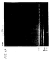
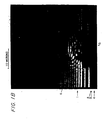
- the material transfer phenomenon of the laser-induced ablation process of the present invention is illustrated by the photomicrographs obtained by time resolved grazing incident microscopy, TRGIM, in Figures 1 A and 1 B.
- FIGURE 1A is a side view photomicrograph of a composite imaging medium used according to the invention and the illuminated space thereabove (in lieu of a receptor element), prior to laser exposure.
- FIGURE 1 B is a like photomicrograph, taken 100 nanoseconds after the initiation of a 260 nanosecond pulse from a Nd:YAG laser, 5, directed through the polyester support, 4, about 6 mm (1 ⁇ 4 inch) from the edge thereof and into the dynamic release layer, 3, and absorbing ablative topcoat, 2 (the imaging medium, per se, is more fully described in the Example 1 which follows), to produce a plume, 6, of ablated materials.
- the horizontal lines, 1, in the space above the medium are interference lines resulting from the use of coherent probe illumination.
- the Nd:YAG laser (1064 nm output from a Quantronics 116FL-O laser controlled by an Anderson Laboratories' DLM-40-IR2.7 acousto-optic modulator and a 40 MHz signal processor) delivered 0.6 J/cm 2 in a 25 micron diameter beam (1/e 2 ).
- FIGURE 2 illustrates the use of an imaging radiation transparent support substrate in the method of the present invention.
- imaging radiation 6 impinges upon the imaging material which comprises an anti-reflection first layer, 5, an imaging radiation transparent support substrate, 1, a dynamic release layer, 2, and an ablative carrier topcoat, 3.
- a receptor element 4, in contiguous registration therewith.
- FIGURE 3 illustrates an alternative embodiment of the present invention wherein the imaging material comprises a nontransparent support substrate, 7.
- the receptor element, 4 is made of imaging radiation transparent material and is provided with an anti-reflection back layer, 5.
- the imaging radiation, 6, impinges upon the imaging material from the front or through the receptor element, into the ablative carrier topcoat, 3, and dynamic release layer, 2.
- a pattern of imaging radiation at the desired wavelength(s) is directed into the absorbing layer(s). This causes ablation of at least the carrier topcoat and its transfer to the receptor element, thus producing an imaged donor film, 8, and a corresponding image of opposite sign, 9, on the receptor element.
- the imaging radiation employed in this invention includes wavelengths in the visible and near infrared spectral regions.
- Near infrared radiation is preferred for color proofing and printing applications because the sensitizers, when indeed they are employed for a particular application, can be substantially colorless in the visible region and thus will not adversely affect the color fidelity of the transferred image on the receptor element.
- Exemplary radiation emitting devices for imagewise exposing the composite imaging media of the invention include solid state lasers, semiconductor diode lasers, gas lasers, dye lasers, xenon lamps, mercury arc lamps, and other visible and near infrared radiation sources which are capable of providing sufficient energy to equal, or exceed, the threshold energy for ablation transfer and of providing this energy at such a rate as to institute that phenomenon of transient pressure accumulation discussed earlier and believed responsible for the ablative transfer process.
- threshold energy is intensity dependent as well as materials dependent.
- imaging media constructions comprising a dynamic release layer composed of high thermal conductivity thin metal films, such as aluminum
- at least 50 mJ/cm 2 at 10 6 watts/cm 2 is required, while at least 100 mJ/cm 2 at 10 4 watts/cm 2 is more typical for organic constructions.
- undesirable processes rather than, or in addition to, ablation-transfer may occur, e.g., melting, sublimation, charring, etc. Incomplete transfer and/or image quality degradation may result.
- Other constraints on the exposure device include the ability to focus the imaging radiation to.a desirable spot size and depth and to modulate the radiation at dwell times suitable for the desired imaging application.
- Particularly representative devices for providing the imaging radiation include lasers such as Nd:YAG lasers emitting at 1064 nm, for example that incorporated in the imaging hardware of the Crosfield Datrax 765 laser facsimile writer, laser diode systems emitting at 780-840 nm, or other radiation sources designed to provide a power density of 10 4 watts/cm 2 or greater.
- lasers such as Nd:YAG lasers emitting at 1064 nm, for example that incorporated in the imaging hardware of the Crosfield Datrax 765 laser facsimile writer, laser diode systems emitting at 780-840 nm, or other radiation sources designed to provide a power density of 10 4 watts/cm 2 or greater.
- the radiation source is preferably focused to provide the most efficient utilization of energy when it is impinged upon the imaging medium.
- the receptor element need not be specially treated or selected to effectively receive materials from the donor medium and can include, for example, those which are well-known in the art of proofing and printing, such as newsprint, coated or uncoated papers of all shades and color, opaque filled and opaque coated plastic sheets, with the printing stock to be employed in the particular color proofing application being preferred.
- Other suitable receptors include fabrics, wood, cardboard, glass, ceramics, leather, metals such as aluminum and copper, rubber, papers and plastics generally, etc.
- the receptor element need not be specially treated or selected to assist in the ablation-transfer process, as indicated above, it is nonetheless also within the scope of this invention to employ a treated or coated receptor, for example a receptor sheet coated with an effective amount of an adhesive or sizing, to aid in the adhesion of the ablated carrier topcoat thereto at lower energy than otherwise would be required.
- the imaging medium is most advantageously positioned and firmly maintained in face-to-face registered direct contact with the particular receptor element selected, to facilely transfer ablated carrier topcoat thereto, by any means suitable for such purpose, e.g., positive pressure, a vacuum, or even by the adhesive properties of the receptor element itself.
- the present invention provides numerous advantages and a versatility hitherto alien to this art.
- the subject composite imaging media are significantly more sensitive to imaging radiation, certain constructions being at least twice as sensitive using far less sensitizer, e. g., at least 75% less, at about half the thickness of the ablative topcoat, to achieve a comparable image density on the receptor element.
- the energy/power requirements for a clean transfer are significantly decreased.
- the ablative carrier topcoat need not itself be sensitized, albeit this is optional; rather, only the dynamic release layer is required to be sensitive to the imaging radiation.
- binder material is expanded and any required amount thereof lessened per the present invention, as decomposable binders are not required, as is the selection of appropriate sensitizers.
- the distribution of energy absorption in the DRL and ablative topcoat is optimized per the present invention and the ablative process is kinetically much faster, a not insubstantial attribute, considering that this permits much faster access to the desired final product.
- a very primary advantage of the invention is its flexibility in enabling virtually any type of topcoat material/pattern of intelligence to be transferred to virtually any receptor element.
- This example describes the production of various composite ablation-transfer imaging media which may be used according to the present invention and also the use of same to prepare a newspaper multi-color proof.
- a four color proof was produced on a Crosfield Datrax 765 reader/writer from the Color Test Negative color separations provided by the American Newspaper Publishers Association (A.N.P.A.).
- the respective color-separated images were scanned by the reader and converted to registered digital electronic signals and transmitted sequentially to the laser writer, a scanning YAG laser adjusted to write 47.3 lines mm -1 (1,200 lines per inch) at 7.5 watts (fluence 160 mJ/cm 2 , power density 10 6 watts/cm 2 , beam diameter 25 microns (1/e 2 ), dwell time about 104 nanoseconds).
- a proof or print was produced by serially and successively placing the aforesaid four imaging media in direct face-to-face contact with a common newspaper stock receptor sheet securedly maintained in place by vacuum in the laser writer and respectively imaging/exposing same.
- the carrier topcoats of the four imaging media were imagewise ablated to the newspaper receptor sheet in primary color areas at the following optical reflection densities (measured using a X-Rite 428 densitometer): CYAN: 0.96 d.u. vs. 0.90 d.u. A.N.P.A. specification MAGENTA: 0.89 d.u. vs. 0.90 d.u. A.N.P.A. specification YELLOW: 0.87 d.u. vs. 0.85 d.u. A.N.P.A. specification BLACK: 1.12 d.u. vs. 1.05 d.u. A.N.P.A. specification
- the 406 x 609 mm (16 x 24 inch) multi-color proof thus produced in about 10 minutes, corresponded favorably to a newspaper press print produced from printing inks containing the same pigments and printing plates produced from the same color-separation negatives.
- This example describes the production of various composite ablation-transfer imaging media which may be used according to the present invention and also the use of same to prepare a magazine multi-color proof.
- the dispersions/suspension prepared as in Example 1 were coated onto the metallized face surfaces of aluminized polyester films of 50% transmission by hand drawdown using a #7 Meyer rod (cyan), a #5 Meyer rod (magenta) and #3 Meyer rod (yellow).
- the black suspension was hand coated onto ICI Melinex 516 polyester film using a #9 Meyer rod.
- the four imaging media were sequentially ablated (Datrax writer adjusted to 47.3 lines mm -1 (1,200 lines per inch) resolution and 8.5 watts, fluence 180 mJ/cm 2 ) onto a #5 ground wood receptor sheet (Ad-Proof Enamel (Trade Mark) from Appleton Paper Inc.) of about 70% brightness and about 27.2 Kg (60 lb.) basis weight, by the technique of Example 1, to provide the following optical reflection densities: CYAN: 1.50 d.u. vs. 1.50 d.u. A.N.P.A. specification MAGENTA: 1.43 d.u. vs. 1.45 d.u. A.N.P.A. specification YELLOW: 1.05 d.u. vs. 1.05 d.u. A.N.P.A. specification BLACK: 1.30 d.u. vs. 1.60 d.u. A.N.P.A. specification
- This example relates to providing an anti-reflection (AR) layer, or coating, on the back surface of a composite ablation-transfer imaging medium which may be used according to the invention and reports certain comparative data obtained by ablating the AR coated and uncoated imaging media onto two different substrates.
- AR anti-reflection
- the uncoated, raw polyester side of a machine coated, 203 x 254 mm (8 x 10 inch) magenta composite imaging medium prepared as in Example 1 was coated with Fluorad FC-721, a 3M fluorochemical coating solution having a refractive index of about 1.36, to a thickness of about 0.2 ⁇ m to 0.25 ⁇ m (cross-sections were measured with a scanning electron microscope) using a #4 Meyer rod.
- the AR coated imaging medium and an uncoated control imaging medium of the same sample were ablatively imaged onto plain, untreated white paper and onto newspaper stock using a Crosfield Datrax 765 Nd:YAG laser writer.
- This example compares the imaging properties of a variety of binder polymers constituting the ablative carrier topcoat of the composite ablation-transfer imaging media used according to the invention.
- the imaging properties of a variety of solvent soluble polymers were compared. Each resin (0.2 grams) was added to 9.8 grams of a mixture containing 0.3% of 2,5-dimethyl-3-hexyne-2,5-diol, 0.7% Cyasorb IR 165, and 5% of Morfast Yellow 101 by weight.
- the solvents selected were a 50:50 mixture of methylene chloride and 1,1,1-trichloroethane or a 50:20:15:15 mixture of methyl ethyl ketone, methyl propyl ketone, n-butyl acetate and cyclohexanone. Appropriate corrections were made for the density differences between the two solvent blends.
- Films were prepared by coating the above solutions onto 50% transmission aluminized polyester with a #3 Meyer rod, to a transmission density (blue filter) of .60. The films were then ablated at three power settings on a Crosfield Datrax 765 Writer with a Nd:YAG laser onto an uncoated white paper to provide a maximum reflectance density of 0.75.
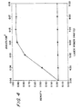
- Imaging sensitivity plots (Laser Power vs. Cyan Density Transferred to the Receptor Sheet) derived from the cyan imaging medium and receptor sheets A as described in Example 1, and a similar cyan imaging medium/receptor B organization, but the latter imaging medium being devoid of a dynamic release layer, were compared.
- a Datrax writer was adjusted to print solid patches of cyan colorant, i.e., maximum density, at 47.3 lines mm -1 (1,200 lines/inch) for 3 watts, 4 watts, 5 watts, 6, watts, 7 watts and 8 watts of power. Average cyan densities, plus paper, were measured on each receptor at each power setting and plotted as shown in the graph of FIGURE 4.
- This example describes the production of various composite ablation-transfer imaging media which may be used according to the present invention, the carrier topcoat thereof being devoid of any sensitizer, and also the use of same to prepare a multi-color proof on an adhesively coated receptor element.
- These imaging media plus the black (K) imaging medium of Example 1 were used to ablate a four color print onto a specially coated receptor sheet using the same imaging/exposure device and under the same writing conditions of Example 1.
- the receptor sheet was prepared by sequentially coating a plain white paper with 3M Spray Mount (Registered Trade Mark) adhesive prior to the successive ablative transfer of images from the respective imaging media, in the order Y,M,C,K. Finally, a protective clear polyester sheet was laminated to the finished print.
- Magenta formulations according to Example 1 were prepared, both with and without the addition of the IR 165. Both formulations were coated as in Example 1 to provide a transmission density of 0.60 ⁇ 0.05 units (green filter). The following receptor sheets were used:
- Magenta imaging media with and without sensitizer were imagewise ablated as described in Example 1 using the magenta film separation from the color test negative supplied by the American Newspaper Publisher's Association. The results and reflection densities reported in the following Table III were obtained: TABLE III: Imaging Medium Receptor 1 Receptor 2 Magenta film without IR 165 no adhesion to receptor 0.90 ⁇ 0.05 at 100% dot Magenta film with IR 165 0.90 ⁇ 0.05 at 100% dot 1.00 ⁇ 0.05 at 100% dot
- a mask was prepared by coating the following formulation:
- the coated film was imagewise ablated onto a porous paper receptor sheet using a Datrax YAG laser writer operating at 8 watts with 47.3 lines mm -1 (1,200 lines/inch) resolution.
- Another type of mask was prepared by coating the following formulation:
- the coated film was imagewise ablated onto a porous paper receptor sheet using a Datrax 765 YAG laser writer operating at 8 watts with 47.3 lines mm -1 (1,200 line/inch) resolution.
- Example 4 The following samples of sputter coated metal films were overcoated with the cyan formulation described in Example 1 using a # 3 Meyer rod by hand drawdown. The actual thickness of the metal layer was unknown; accordingly, the films were characterized by their visible transmission densities (VTD) of the uncoated films.
- the films were imaged using a Nd:YAG laser at 1064 nm output delivering 0.10 J/cm 2 , 0.16 J/cm 2 or 0.22 J/cm 2 in 104 nanoseconds using an uncoated newsprint receptor. The percentage of material transferred was calculated as in Example 4.
Claims (18)
- Verfahren zum Übertragen eines konstrastierenden Musters von Information von einem Ablationsübertragungs-Abbildungsmedium (1, 2, 3; 2, 3, 7) zu einem Rezeptor- bzw. Empfängerelement (4) in aneinandergrenzender Lagenauigkeit damit, wobei das Medium folgendes umfaßt:(i) ein Trägersubstrat (1; 7)(ii) wenigstens eine zwischenliegende dynamische Freisetzungs- bzw. Trennschicht (2), die im wesentlichen koextensiv mit dem Substrat (1; 7) ist bzw. sich im wesentlichen gemeinsam mit dem Substrat (1; 7) erstreckt; und(iii) eine strahlungsablative obere Beschichtung bzw. dünne Oberschicht (3), die auch im wesentlichen koextensiv mit dem Substrat (1 ; 7) ist bzw. sich auch im wesentlichen gemeinsam mit dem Substrat (1 ; 7) erstreckt,wobei die dynamische Freisetzungs- bzw. Trennschicht und/oder die obere Beschichtung bzw. dünne Oberschicht wenigstens ein strahlungsablatives Bindemittel enthält bzw. enthalten,
wobei die dynamische Freisetzungs- bzw. Trennschicht (2) fähig ist, Strahlung (6) mit einer Rate zu absorbieren, die genügend ist, um die bildweise Ablationsmassenübertragung der oberen Beschichtung bzw. dünnen Oberschicht (3) auf das Rezeptor- bzw. Empfängerelement (4) zu bewirken,
welches Verfahren das bildweise Bestrahlen des Mediums (1, 2, 3; 2, 3, 7) entsprechend einem solchen Muster von Information mit einer Intensität umfaßt, welche ausreicht, die bildweise Ablationsmassenübertragung des Volumens des bildweise exponierten Bereichs von wenigstens der oberen Bschichtung bzw. dünnen Oberschicht (3) des Mediums (1, 2, 3; 2, 3, 7) sicher auf das Rezeptor- bzw. Empfängerelement (4) zu bewirken,
dadurch gekennzeichnet, daß die dynamische Freisetzungs- bzw. Trennschicht (2) einen Nicht-Schwarzer-Körper-Strahlungsabsorber enthält, aber frei von Schwarzer-Körper-Strahlungsabsorber ist und daß die obere Beschichtung bzw. dünne Oberschicht (3) eine Abbildungsmenge von einem Nicht-Schwarzer-Körper-Kontrastabbildungsmaterial enthält,
wobei dieses Kontrastabbildungsmaterial zu dem Rezeptor- bzw. Empfängerelement (4) übertragen wird, um das Muster an Information darauf darzustellen bzw. aufzuzeichnen. - Verfahren gemäß Anspruch 1, dadurch gekennzeichnet, daß die dynamische Freisetzungs- bzw. Trennschicht (2) einen dünnen Film aus einem Metall, Metalloxid oder Metallsulfid umfaßt bzw. enthält.
- Verfahren gemäß Anspruch 2, dadurch gekennzeichnet, daß die dynamische Freisetzungs- bzw. Trennschicht (2) folgendes umfaßt bzw. enthält:a) ein Metall der Gruppe Ib, IIb, IIIa, IVa, IVb, Va, Vb, VIa, VIb, VIIb oder VIII des periodischen Systems;b) eine Legierung der oben im Absatz a) erwähnten Metalle;c) eine Legierung von wenigstens einem der im Absatz a) oben erwähnten Metalle mit einem Element der Gruppe Ia, IIa oder IIIb des periodischen Systems;d) Al, Bi, Sn, In oder Zn, oder eine Legierung hiervon;e) ein Metalloxid oder -sulfid von Al, Bi, Sn, In, Zn, Ti, Cr, Mo, W, Co, Ir, Ni, Pd, Pt, Cu, Ag, Au, Zr oder Te;f) Ge.
- Verfahren gemäß Anspruch 1, dadurch gekennzeichnet, daß die dynamische Freisetzungs- bzw. Trennschicht (2) ein sensibilisiertes Flüssigkristallmaterial umfaßt bzw. enthält.
- Verfahren gemäß Anspruch 1, dadurch gekennzeichnet, daß die dynamische Freisetzungs- bzw. Trennschicht (2) ein organisches Material umfaßt bzw. enthält.
- Verfahren gemäß Anspruch 5, dadurch gekennzeichnet, daß das organische Material folgendes ist:a) eine Metallphthalocyanin-, Dithiolen- oder Anthrachinonverbindung; oderb) ein Polythiophen, Polyanilin, Polyacetylen, Polyphenylen, Polyphenylensulfid, Polypyrrol, oder ein Abkömmling oder eine Mischung hiervon.
- Verfahren gemäß irgendeinem der vorhergehenden Ansprüche, dadurch gekennzeichnet , daß wenigstens ein Teil der dynamischen Freisetzungs- bzw. Trennschicht (2) gemeinsam bildweise auf das Rezeptor- bzw. Empfängerelement ablatiert wird.
- Verfahren gemäß irgendeinem der vorhergehenden Ansprüche, dadurch gekennzeichnet , daß die obere Beschichtung bzw. dünne Oberschicht (3) wenigstens ein strahlungsablatives Bindemittel und wenigstens einen Nicht-Schwarzer-Körper-Strahlungsabsorber/Sensibilisierer umfaßt bzw. enthält.
- Verfahren gemäß irgendeinem der vorhergehenden Ansprüche, dadurch gekennzeichnet, daß das Konstrastabbildungsmaterial einen Nichtablations-Sensibilisierungs-Sichtbar-Farbstoff oder ein Nichtablations-Sensibilisierungs-Sichtbar-Pigment, ein ultraviolett- oder infrarotabsorbierendes Material, ein magnetisches Material, ein Polymermaterial, ein fluoreszentes Material, ein elektrisch leitendes Material oder eine Mischung hiervon umfaßt bzw. enthält.
- Verfahren gemäß Anspruch 9, dadurch gekennzeichnet, daß das Kontrastabbildungsmaterial Curcumin, ein Azo-Derivat, ein Oxadiazolderivat, ein Dicinnamalacetonderivat, ein Benzophenonderivat, ein fluoreszierendes Oxazol, Oxadiazol, Coumarin oder ein Carbostyrylderivat umfaßt bzw. enthält.
- Verfahren gemäß irgendeinem der vorhergehenden Ansprüche, dadurch gekennzeichnet, daß das Substrat (1; 7)) Glas, ein Polyester, ein Polycarbonat, ein Polyurethan, ein Polyolefin, ein Polyamid, ein Polysulfon, ein Polystyrol, ein Cellulosematerial, Aluminium oder Silizium umfaßt bzw. enthält.
- Verfahren gemäß irgendeinem der vorhergehenden Ansprüche, dadurch gekennzeichnet, daß das Medium weiter eine Antireflexionsschicht (5) auf der Oberfläche des Substrats (1; 7) gegenüber bzw. entgegengesetzt der obren Beschichtung bzw. dünnen Oberschicht (3) umfaßt bzw. enthält.
- Verfahren gemäß irgendeinem der vorhergehenden Ansprüche, dadurch gekennzeichnet, daß die bildweise Bestrahlung des Mediums (1, 2, 3; 2, 3, 7) mit einem Nd:YAG-Laser, einer Laserdiode oder einer Anordnung bzw. Gruppierung von Laserdioden bewirkt wird.
- Verfahren gemäß irgendeinem der vorhergehenden Ansprüche, dadurch gekennzeichnet, daß die bildweise Bestrahlung des Mediums (1, 2, 3; 2, 3, 7) mit einer Leistungsdichte von wenigstens 104 Watt/cm2 bewirkt wird.
- Verfahren gemäß irgendeinem der vorhergehenden Ansprüche, dadurch gekennzeichnet, daß es ausgeführt wird, indem aufeinanderfolgend ein gemeinsames Rezeptor- bzw. Empfängerelement, jedoch eine Mehrzahl von Ablationsübertragungsabbildungsmedien angewandt wird bzw. werden,
wobei die jeweiligen ablativen oberen Beschichtungen bzw. dünnen Oberschichten hiervon unterschiedliche Kontrastabbildungsfärbemittel enthalten, und umfassend das Übertragen eines Multifarbproofs bzw. eines Multifarbprobedrucks auf das gemeinsame Rezeptor- bzw. Empfängerelement. - Verfahren gemäß irgendeinem der vorhergehenden Ansprüche, dadurch gekennzeichnet, daß die dynamische Freisetzungs- bzw. Trennschicht (2) ein Laserstrahlung absorbierendes polymeres Bindemittel umfaßt bzw. enthält.
- Verfahren gemäß Anspruch 9, dadurch gekennzeichnet, daß das strahlungsablative Bindemittel Nitrocellulose, Polycarbonat, Polyurethan, Polyester, Polyorthoester oder Polyacetal umfaßt bzw. enthält.
- Verfahren gemäß Anspruch 9, dadurch gekennzeichnet, daß das strahlungsablative Bindemittel ein Polysulfon, Styrol/Acrylnitril-Polymer, Celluloseether oder ester, Polymethacrylat, Polyvinylidenchlorid, α-Chloroacrylnitril, Maleinsäurepolymer, ein Copolymer oder einen Abkömmling hiervon umfaßt bzw. enthält.
Applications Claiming Priority (5)
| Application Number | Priority Date | Filing Date | Title |
|---|---|---|---|
| US59279090A | 1990-10-04 | 1990-10-04 | |
| US707039 | 1991-05-29 | ||
| US07/707,039 US5171650A (en) | 1990-10-04 | 1991-05-29 | Ablation-transfer imaging/recording |
| PCT/US1991/006813 WO1992006410A1 (en) | 1990-10-04 | 1991-09-25 | Improved ablation-transfer imaging/recording |
| US592790 | 1996-01-26 |
Publications (4)
| Publication Number | Publication Date |
|---|---|
| EP0552251A1 EP0552251A1 (de) | 1993-07-28 |
| EP0552251A4 EP0552251A4 (en) | 1993-08-18 |
| EP0552251B1 EP0552251B1 (de) | 2001-01-10 |
| EP0552251B2 true EP0552251B2 (de) | 2007-03-14 |
Family
ID=27081548
Family Applications (1)
| Application Number | Title | Priority Date | Filing Date |
|---|---|---|---|
| EP91918702A Expired - Lifetime EP0552251B2 (de) | 1990-10-04 | 1991-09-25 | Bilderzeugung/aufzeichnung durch verbesserte abtragungs-übertragung |
Country Status (10)
| Country | Link |
|---|---|
| US (1) | US5171650A (de) |
| EP (1) | EP0552251B2 (de) |
| JP (3) | JP3334877B2 (de) |
| AT (1) | ATE198565T1 (de) |
| AU (1) | AU669649B2 (de) |
| CA (1) | CA2093413C (de) |
| DE (1) | DE69132508T3 (de) |
| DK (1) | DK0552251T3 (de) |
| ES (1) | ES2153821T5 (de) |
| WO (1) | WO1992006410A1 (de) |
Families Citing this family (232)
| Publication number | Priority date | Publication date | Assignee | Title |
|---|---|---|---|---|
| US5501938A (en) * | 1989-03-30 | 1996-03-26 | Rexham Graphics Inc. | Ablation-transfer imaging/recording |
| DE4118457A1 (de) * | 1991-06-05 | 1992-12-10 | Max Planck Gesellschaft | Verfahren zum speichern von information in einem optisch lesbaren datenspeicher |
| EP0566103B1 (de) * | 1992-04-14 | 1998-03-18 | Konica Corporation | Wärmeempfindliches Übertragungsaufzeichnungsmaterial |
| US5339737B1 (en) * | 1992-07-20 | 1997-06-10 | Presstek Inc | Lithographic printing plates for use with laser-discharge imaging apparatus |
| AU714487B2 (en) * | 1992-07-20 | 2000-01-06 | Presstek, Inc. | Lithographic printing plates for use with laser-discharge imaging apparatus |
| USRE35512F1 (en) * | 1992-07-20 | 1998-08-04 | Presstek Inc | Lithographic printing members for use with laser-discharge imaging |
| US5379698A (en) * | 1992-07-20 | 1995-01-10 | Presstek, Inc. | Lithographic printing members for use with laser-discharge imaging |
| US5353705A (en) * | 1992-07-20 | 1994-10-11 | Presstek, Inc. | Lithographic printing members having secondary ablation layers for use with laser-discharge imaging apparatus |
| AU674518B2 (en) * | 1992-07-20 | 1997-01-02 | Presstek, Inc. | Lithographic printing plates for use with laser-discharge imaging apparatus |
| US5719009A (en) * | 1992-08-07 | 1998-02-17 | E. I. Du Pont De Nemours And Company | Laser ablatable photosensitive elements utilized to make flexographic printing plates |
| US5262275A (en) * | 1992-08-07 | 1993-11-16 | E. I. Du Pont De Nemours And Company | Flexographic printing element having an IR ablatable layer and process for making a flexographic printing plate |
| US5278023A (en) * | 1992-11-16 | 1994-01-11 | Minnesota Mining And Manufacturing Company | Propellant-containing thermal transfer donor elements |
| WO1994011785A1 (en) * | 1992-11-18 | 1994-05-26 | Rexham Graphics Inc. | On-demand production of lat imaging films |
| US5308737A (en) * | 1993-03-18 | 1994-05-03 | Minnesota Mining And Manufacturing Company | Laser propulsion transfer using black metal coated substrates |
| US6916596B2 (en) | 1993-06-25 | 2005-07-12 | Michael Wen-Chein Yang | Laser imaged printing plates |
| DE4339010C2 (de) * | 1993-06-25 | 2000-05-18 | Pt Sub Inc | Photohärtbares Erzeugnis für Druckplatten |
| US6756181B2 (en) | 1993-06-25 | 2004-06-29 | Polyfibron Technologies, Inc. | Laser imaged printing plates |
| US5387496A (en) * | 1993-07-30 | 1995-02-07 | Eastman Kodak Company | Interlayer for laser ablative imaging |
| US5330876A (en) * | 1993-07-30 | 1994-07-19 | Eastman Kodak Company | High molecular weight binders for laser ablative imaging |
| DE69407888T2 (de) * | 1993-07-30 | 1998-04-30 | Eastman Kodak Co | Sperrschicht für ein Bilderzeugungsverfahren durch Laserablation |
| DE69402268T2 (de) * | 1993-07-30 | 1997-07-10 | Eastman Kodak Co | Infrarot absorbierende Cyaninfarbstoffe für die Laserablativabbildung |
| JPH09501620A (ja) * | 1993-08-13 | 1997-02-18 | レクスハム・グラフィクス・インコーポレーテッド | 中間レセプターへのアブレーション転写 |
| US5354633A (en) * | 1993-09-22 | 1994-10-11 | Presstek, Inc. | Laser imageable photomask constructions |
| EP0649757B1 (de) * | 1993-10-25 | 1996-12-11 | Agfa-Gevaert N.V. | Wärmeempfindliches Aufzeichnungsmaterial und Bildaufzeichnungsverfahren, das dieses Material verwendet |
| US5399459A (en) * | 1993-10-26 | 1995-03-21 | Eastman Kodak Company | Thermally bleachable dyes for laser ablative imaging |
| US5326619A (en) * | 1993-10-28 | 1994-07-05 | Minnesota Mining And Manufacturing Company | Thermal transfer donor element comprising a substrate having a microstructured surface |
| US6037968A (en) * | 1993-11-09 | 2000-03-14 | Markem Corporation | Scanned marking of workpieces |
| US5757313A (en) * | 1993-11-09 | 1998-05-26 | Markem Corporation | Lacer-induced transfer printing medium and method |
| WO1995013566A1 (en) * | 1993-11-10 | 1995-05-18 | Xmr, Inc. | Method for back-side photo-induced ablation for making a color filter, or the like |
| US5459016A (en) * | 1993-12-16 | 1995-10-17 | Minnesota Mining And Manufacturing Company | Nanostructured thermal transfer donor element |
| JPH09506565A (ja) * | 1993-12-17 | 1997-06-30 | ミネソタ・マイニング・アンド・マニュファクチュアリング・カンパニー | 近接石版印刷を利用した削摩による結像 |
| US5440987A (en) * | 1994-01-21 | 1995-08-15 | Presstek, Inc. | Laser imaged seamless lithographic printing members and method of making |
| US5451485A (en) * | 1994-03-04 | 1995-09-19 | Eastman Kodak Company | Interlayer addendum for laser ablative imaging |
| US5574493A (en) * | 1994-03-11 | 1996-11-12 | Eastman Kodak Company | Vacuum collection system for dye-ablation printing process |
| FI103396B (fi) * | 1994-03-24 | 1999-06-30 | Laserplus Oy | Menetelmä ja laite merkkausten tekemiseksi lasipintaan |
| US5518861A (en) * | 1994-04-26 | 1996-05-21 | E. I. Du Pont De Nemours And Company | Element and process for laser-induced ablative transfer |
| EP0679531B1 (de) * | 1994-04-26 | 1997-07-23 | E.I. Du Pont De Nemours And Company | Element und Verfahren für ablative Übertragung durch Laser |
| US5510227A (en) * | 1994-06-14 | 1996-04-23 | Eastman Kodak Company | Image dye for laser ablative recording process |
| US5468591A (en) * | 1994-06-14 | 1995-11-21 | Eastman Kodak Company | Barrier layer for laser ablative imaging |
| US5563019A (en) * | 1994-06-30 | 1996-10-08 | E. I. Du Pont De Nemours And Company | Donor element for laser-induced thermal transfer |
| DE69500683T2 (de) * | 1994-06-30 | 1998-02-19 | Du Pont | Donor-element für thermische Übertragung durch Laser |
| US5521035A (en) * | 1994-07-11 | 1996-05-28 | Minnesota Mining And Manufacturing Company | Methods for preparing color filter elements using laser induced transfer of colorants with associated liquid crystal display device |
| US6057067A (en) * | 1994-07-11 | 2000-05-02 | 3M Innovative Properties Company | Method for preparing integral black matrix/color filter elements |
| US5429909A (en) * | 1994-08-01 | 1995-07-04 | Eastman Kodak Company | Overcoat layer for laser ablative imaging |
| US6218071B1 (en) | 1994-08-24 | 2001-04-17 | Eastman Kodak Company | Abrasion-resistant overcoat layer for laser ablative imaging |
| US5529884A (en) * | 1994-12-09 | 1996-06-25 | Eastman Kodak Company | Backing layer for laser ablative imaging |
| US5491045A (en) * | 1994-12-16 | 1996-02-13 | Eastman Kodak Company | Image dye combination for laser ablative recording element |
| US5569568A (en) * | 1994-12-16 | 1996-10-29 | Eastman Kodak Company | Method for using a laser ablative recording element with low red or green absorption as a reprographic photomask |
| US5521050A (en) * | 1994-12-16 | 1996-05-28 | Eastman Kodak Company | UV dyes for laser ablative recording process |
| US5819661A (en) * | 1995-01-23 | 1998-10-13 | Presstek, Inc. | Method and apparatus for laser imaging of lithographic printing members by thermal non-ablative transfer |
| US5693447A (en) * | 1995-02-17 | 1997-12-02 | Konica Corporation | Image forming material, method of preparing the same and image forming method employing the same |
| US5510228A (en) * | 1995-02-17 | 1996-04-23 | Eastman Kodak Company | 2-cyano-3,3-diarylacrylate UV dyes for laser recording process |
| US5576142A (en) * | 1995-02-17 | 1996-11-19 | Eastman Kodak Company | 2-hydroxybenzophenone UV dyes for laser recording process |
| US5576141A (en) * | 1995-02-17 | 1996-11-19 | Eastman Kodak Company | Benzotriazole UV dyes for laser recording process |
| US5521051A (en) * | 1995-02-17 | 1996-05-28 | Eastman Kodak Company | Oxalanilide UV dyes for laser recording element |
| US5685939A (en) * | 1995-03-10 | 1997-11-11 | Minnesota Mining And Manufacturing Company | Process for making a Z-axis adhesive and establishing electrical interconnection therewith |
| DE69601432T2 (de) * | 1995-03-16 | 1999-10-07 | Minnesota Mining & Mfg | Schwarz-Metall wärmebildbare Transparenz-Elemente |
| US5633113A (en) * | 1995-04-14 | 1997-05-27 | Polaroid Corporation | Mass transfer imaging media and methods of making and using the same |
| GB9508031D0 (en) * | 1995-04-20 | 1995-06-07 | Minnesota Mining & Mfg | UV-absorbing media bleachable by IR-radiation |
| US5945249A (en) * | 1995-04-20 | 1999-08-31 | Imation Corp. | Laser absorbable photobleachable compositions |
| GB9617416D0 (en) * | 1996-08-20 | 1996-10-02 | Minnesota Mining & Mfg | Thermal bleaching of infrared dyes |
| US5935758A (en) * | 1995-04-20 | 1999-08-10 | Imation Corp. | Laser induced film transfer system |
| US6238837B1 (en) | 1995-05-01 | 2001-05-29 | E.I. Du Pont De Nemours And Company | Flexographic element having an infrared ablatable layer |
| WO1996034767A1 (en) * | 1995-05-01 | 1996-11-07 | Polaroid Corporation | Composite ablation-transfer imaging medium for printing plate production |
| DE69610579T2 (de) * | 1995-05-31 | 2001-02-15 | Kodak Polychrome Graphics Llc | Verfahren zur Herstellung eines Bildaufzeichnungselements |
| US6143470A (en) * | 1995-06-23 | 2000-11-07 | Nguyen; My T. | Digital laser imagable lithographic printing plates |
| US5750323A (en) * | 1995-08-31 | 1998-05-12 | Eastman Kodak Company | Solid particle dispersions for imaging elements |
| JP3625089B2 (ja) * | 1995-09-13 | 2005-03-02 | 富士写真フイルム株式会社 | 湿し水不要平版印刷版の形成方法 |
| US6685868B2 (en) | 1995-10-30 | 2004-02-03 | Darryl Costin | Laser method of scribing graphics |
| US5990444A (en) * | 1995-10-30 | 1999-11-23 | Costin; Darryl J. | Laser method and system of scribing graphics |
| US6252196B1 (en) | 1996-10-11 | 2001-06-26 | Technolines Llc | Laser method of scribing graphics |
| US5674661A (en) * | 1995-10-31 | 1997-10-07 | Eastman Kodak Company | Image dye for laser dye removal recording element |
| US6105500A (en) * | 1995-11-24 | 2000-08-22 | Kodak Polychrome Graphics Llc | Hydrophilized support for planographic printing plates and its preparation |
| US5766819A (en) * | 1995-11-29 | 1998-06-16 | E. I. Dupont De Nemours And Company | Donor elements, assemblages, and associated processes with flexible ejection layer(s) for laser-induced thermal transfer |
| EP0790138B1 (de) | 1996-02-15 | 1999-10-20 | Minnesota Mining And Manufacturing Company | Laserinduziertes Aufzeichnungsverfahren mit thermischer Übertragung durch Wärme |
| US5725706A (en) * | 1996-03-12 | 1998-03-10 | The Whitaker Corporation | Laser transfer deposition |
| US5792579A (en) * | 1996-03-12 | 1998-08-11 | Flex Products, Inc. | Method for preparing a color filter |
| US5695907A (en) * | 1996-03-14 | 1997-12-09 | Minnesota Mining And Manufacturing Company | Laser addressable thermal transfer imaging element and method |
| US5691098A (en) * | 1996-04-03 | 1997-11-25 | Minnesota Mining And Manufacturing Company | Laser-Induced mass transfer imaging materials utilizing diazo compounds |
| US5747217A (en) * | 1996-04-03 | 1998-05-05 | Minnesota Mining And Manufacturing Company | Laser-induced mass transfer imaging materials and methods utilizing colorless sublimable compounds |
| US5725989A (en) | 1996-04-15 | 1998-03-10 | Chang; Jeffrey C. | Laser addressable thermal transfer imaging element with an interlayer |
| US7534543B2 (en) * | 1996-04-15 | 2009-05-19 | 3M Innovative Properties Company | Texture control of thin film layers prepared via laser induced thermal imaging |
| US5693446A (en) * | 1996-04-17 | 1997-12-02 | Minnesota Mining And Manufacturing Company | Polarizing mass transfer donor element and method of transferring a polarizing mass transfer layer |
| US5710097A (en) * | 1996-06-27 | 1998-01-20 | Minnesota Mining And Manufacturing Company | Process and materials for imagewise placement of uniform spacers in flat panel displays |
| US5998085A (en) * | 1996-07-23 | 1999-12-07 | 3M Innovative Properties | Process for preparing high resolution emissive arrays and corresponding articles |
| GB9617415D0 (en) * | 1996-08-20 | 1996-10-02 | Minnesota Mining & Mfg | Production of colour proofs and printing plates |
| EP0827008A3 (de) * | 1996-08-31 | 1998-11-18 | Samsung Display Devices Co., Ltd. | Eine Flachbildschirmvorrichtung und deren Herstellungsverfahren |
| US20020064728A1 (en) * | 1996-09-05 | 2002-05-30 | Weed Gregory C. | Near IR sensitive photoimageable/photopolymerizable compositions, media, and associated processes |
| US6013409A (en) * | 1996-09-10 | 2000-01-11 | 3M Innovative Properties Company | Dry peel-apart imaging process |
| US5856064A (en) * | 1996-09-10 | 1999-01-05 | Minnesota Mining And Manufacturing Company | Dry peel-apart imaging or proofing system |
| US6261739B1 (en) * | 1996-09-11 | 2001-07-17 | Fuji Photo Film Co., Ltd. | Laser ablative recording material |
| US5897727A (en) * | 1996-09-20 | 1999-04-27 | Minnesota Mining And Manufacturing Company | Method for assembling layers with a transfer process using a crosslinkable adhesive layer |
| US5858624A (en) * | 1996-09-20 | 1999-01-12 | Minnesota Mining And Manufacturing Company | Method for assembling planarization and indium-tin-oxide layer on a liquid crystal display color filter with a transfer process |
| GB9624224D0 (en) | 1996-11-21 | 1997-01-08 | Horsell Graphic Ind Ltd | Planographic printing |
| US6143451A (en) * | 1996-11-26 | 2000-11-07 | E. I. Du Pont De Nemours And Company | Imaged laserable assemblages and associated processes with high speed and durable image-transfer characteristics for laser-induced thermal transfer |
| KR100195175B1 (ko) * | 1996-12-23 | 1999-06-15 | 손욱 | 유기전자발광소자 유기박막용 도너필름, 이를 이용한 유기전자발광소자의 제조방법 및 그 방법에 따라 제조된 유기전자발광소자 |
| US5786129A (en) * | 1997-01-13 | 1998-07-28 | Presstek, Inc. | Laser-imageable recording constructions utilizing controlled, self-propagating exothermic chemical reaction mechanisms |
| GB9702568D0 (en) * | 1997-02-07 | 1997-03-26 | Horsell Graphic Ind Ltd | Planographic printing |
| US5854175A (en) * | 1997-04-09 | 1998-12-29 | Eastman Kodak Company | Embossed compact disc surfaces for laser thermal labeling |
| US6357351B1 (en) | 1997-05-23 | 2002-03-19 | Kodak Polychrome Graphics Llc | Substrate for planographic printing |
| GB9710552D0 (en) | 1997-05-23 | 1997-07-16 | Horsell Graphic Ind Ltd | Planographic printing |
| US5858583A (en) * | 1997-07-03 | 1999-01-12 | E. I. Du Pont De Nemours And Company | Thermally imageable monochrome digital proofing product with high contrast and fast photospeed |
| US5955224A (en) * | 1997-07-03 | 1999-09-21 | E. I. Du Pont De Nemours And Company | Thermally imageable monochrome digital proofing product with improved near IR-absorbing dye(s) |
| US5840463A (en) * | 1997-07-14 | 1998-11-24 | E. I. Du Pont De Nemours And Company | Photosensitive donor element assemblages and associated process for laser-induced thermal transfer |
| US6315202B2 (en) * | 1997-08-11 | 2001-11-13 | Technolines, Llc. | Material coding using lasers |
| US5856061A (en) * | 1997-08-14 | 1999-01-05 | Minnesota Mining And Manufacturing Company | Production of color proofs and printing plates |
| US6001530A (en) * | 1997-09-02 | 1999-12-14 | Imation Corp. | Laser addressed black thermal transfer donors |
| US6025110A (en) * | 1997-09-18 | 2000-02-15 | Nowak; Michael T. | Method and apparatus for generating three-dimensional objects using ablation transfer |
| US6361905B2 (en) | 1997-09-26 | 2002-03-26 | Flex Products, Inc. | Color filters for displays |
| JPH11123871A (ja) | 1997-10-22 | 1999-05-11 | Konica Corp | 画像形成材料及びその製造方法と画像形成装置 |
| US6132934A (en) * | 1998-02-09 | 2000-10-17 | Agfa-Gevaert, N.V. | Heat-sensitive imaging material for making lithographic printing plates requiring no processing |
| US6251571B1 (en) | 1998-03-10 | 2001-06-26 | E. I. Du Pont De Nemours And Company | Non-photosensitive, thermally imageable element having improved room light stability |
| US5994026A (en) * | 1998-03-30 | 1999-11-30 | Eastman Kodak Company | Flexographic printing plate with mask layer and methods of imaging and printing |
| US6114088A (en) | 1999-01-15 | 2000-09-05 | 3M Innovative Properties Company | Thermal transfer element for forming multilayer devices |
| EP1144197B1 (de) | 1999-01-15 | 2003-06-11 | 3M Innovative Properties Company | Thermisches Übertragungsverfahren. |
| US6168903B1 (en) | 1999-01-21 | 2001-01-02 | Presstek, Inc. | Lithographic imaging with reduced power requirements |
| US6177151B1 (en) | 1999-01-27 | 2001-01-23 | The United States Of America As Represented By The Secretary Of The Navy | Matrix assisted pulsed laser evaporation direct write |
| US6936311B2 (en) | 1999-01-27 | 2005-08-30 | The United States Of America As Represented By The Secretary Of The Navy | Generation of biomaterial microarrays by laser transfer |
| US6905738B2 (en) | 1999-01-27 | 2005-06-14 | The United States Of America As Represented By The Secretary Of The Navy | Generation of viable cell active biomaterial patterns by laser transfer |
| AU2514800A (en) | 1999-01-27 | 2000-08-18 | United States Of America As Represented By The Secretary Of The Navy, The | Matrix assisted pulsed laser evaporation direct write |
| US6461775B1 (en) * | 1999-05-14 | 2002-10-08 | 3M Innovative Properties Company | Thermal transfer of a black matrix containing carbon black |
| AU6057900A (en) * | 1999-07-22 | 2001-02-13 | Robotic Vision Systems, Inc. | Apparatuses and methods for applying an indelible and contrasting pattern onto acarrier |
| US6293197B1 (en) | 1999-08-17 | 2001-09-25 | Kodak Polychrome Graphics | Hydrophilized substrate for planographic printing |
| US6228543B1 (en) | 1999-09-09 | 2001-05-08 | 3M Innovative Properties Company | Thermal transfer with a plasticizer-containing transfer layer |
| AU6655000A (en) * | 1999-10-15 | 2001-04-26 | E.I. Du Pont De Nemours And Company | Thermal imaging process providing color versatility |
| US6294308B1 (en) | 1999-10-15 | 2001-09-25 | E. I. Du Pont De Nemours And Company | Thermal imaging process and products using image rigidification |
| US6165654A (en) | 1999-10-15 | 2000-12-26 | E. I. Du Pont De Nemours And Company | Analog and digital proofing image combinations |
| US6583916B2 (en) | 1999-11-03 | 2003-06-24 | Optodot Corporation | Optical shutter assembly |
| AU772671B2 (en) | 1999-11-03 | 2004-05-06 | Optodot Corporation | Optical shutter |
| US6521324B1 (en) | 1999-11-30 | 2003-02-18 | 3M Innovative Properties Company | Thermal transfer of microstructured layers |
| US6284425B1 (en) | 1999-12-28 | 2001-09-04 | 3M Innovative Properties | Thermal transfer donor element having a heat management underlayer |
| US6228555B1 (en) | 1999-12-28 | 2001-05-08 | 3M Innovative Properties Company | Thermal mass transfer donor element |
| US6165671A (en) * | 1999-12-30 | 2000-12-26 | Eastman Kodak Company | Laser donor element |
| US6284441B1 (en) | 2000-02-29 | 2001-09-04 | Eastman Kodak Company | Process for forming an ablation image |
| US6235454B1 (en) | 2000-02-29 | 2001-05-22 | Eastman Kodak Company | Process for forming an ablation image |
| US6242152B1 (en) | 2000-05-03 | 2001-06-05 | 3M Innovative Properties | Thermal transfer of crosslinked materials from a donor to a receptor |
| US6190827B1 (en) | 2000-05-04 | 2001-02-20 | Eastman Kodak Company | Laser donor element |
| WO2001087634A2 (en) | 2000-05-16 | 2001-11-22 | E.I. Du Pont De Nemours And Company | Aqueous dispersions for color imaging |
| US6926790B2 (en) * | 2000-05-17 | 2005-08-09 | E. I. Du Pont De Nemours And Company | Overcoated donor elements and their process of use |
| AU2000261986A1 (en) * | 2000-07-20 | 2003-12-12 | The United States Of America As Represented By The Secretary Of The Navy | Direct-write laser transfer and processing |
| US6855384B1 (en) * | 2000-09-15 | 2005-02-15 | 3M Innovative Properties Company | Selective thermal transfer of light emitting polymer blends |
| US6358664B1 (en) | 2000-09-15 | 2002-03-19 | 3M Innovative Properties Company | Electronically active primer layers for thermal patterning of materials for electronic devices |
| JP2002127476A (ja) * | 2000-10-26 | 2002-05-08 | Fuji Photo Film Co Ltd | 記録装置 |
| US7005407B2 (en) * | 2000-11-21 | 2006-02-28 | E. I. Du Pont De Nemours And Company | Thermal imaging elements having improved stability |
| US6645681B2 (en) | 2000-12-15 | 2003-11-11 | E. I. Du Pont De Nemours And Company | Color filter |
| US6958202B2 (en) * | 2000-12-15 | 2005-10-25 | E.I. Du Pont De Nemours And Company | Donor element for adjusting the focus of an imaging laser |
| DE60110459T2 (de) * | 2000-12-15 | 2006-01-26 | E.I. Du Pont De Nemours And Co., Wilmington | Trägerschicht eines donorelements zur einstellung des brennpunktes eines bilderzeugungslasers |
| WO2002047917A2 (en) * | 2000-12-15 | 2002-06-20 | E. I. Du Pont De Nemours And Company | Receiver element for adjusting the focus of an imaging laser |
| KR20040030506A (ko) * | 2001-02-16 | 2004-04-09 | 이 아이 듀폰 디 네모아 앤드 캄파니 | 고전도성 폴리아닐린 조성물 및 그의 용도 |
| US6852355B2 (en) | 2001-03-01 | 2005-02-08 | E. I. Du Pont De Nemours And Company | Thermal imaging processes and products of electroactive organic material |
| WO2002092352A1 (en) | 2001-05-11 | 2002-11-21 | E.I. Du Pont De Nemours And Company | High resolution laserable assemblages for laser-induced thermal image transfer |
| US6692895B2 (en) * | 2001-05-25 | 2004-02-17 | 3M Innovative Properties Company | Imageable article and method of imaging |
| MXPA04002065A (es) | 2001-09-04 | 2005-02-17 | Kodak Polychrome Graphics Llc | Metodo de prueba hibrido. |
| TWI297809B (de) * | 2001-10-24 | 2008-06-11 | Toyo Boseki | |
| US20030124265A1 (en) * | 2001-12-04 | 2003-07-03 | 3M Innovative Properties Company | Method and materials for transferring a material onto a plasma treated surface according to a pattern |
| WO2003066339A1 (en) | 2002-02-06 | 2003-08-14 | E.I. Du Pont De Nemours And Company | Image transfer element, laser assemblage and process for thermal imaging |
| DE10210146A1 (de) * | 2002-03-07 | 2003-09-25 | Aurentum Innovationstechnologi | Qualitätsdruckverfahren und Druckmaschine sowie Drucksbustanz hierfür |
| WO2003098351A1 (en) * | 2002-05-17 | 2003-11-27 | E.I. Du Pont De Nemours And Company | Radiation filter element and manufacturing processes therefore |
| JP2005526293A (ja) * | 2002-05-17 | 2005-09-02 | イー・アイ・デュポン・ドウ・ヌムール・アンド・カンパニー | カラーフィルタのサーマルプリンティング用平坦化要素 |
| JP2005534046A (ja) | 2002-05-17 | 2005-11-10 | イー・アイ・デュポン・ドウ・ヌムール・アンド・カンパニー | カラーフィルタのサーマルプリンティングのドナー要素用の低分子量アクリルコポリマーラテックス |
| AU2003249552A1 (en) * | 2002-08-07 | 2004-02-25 | Vim Technologies Ltd. | Lithographic printing members and a method and a system for preparation of lithographic printing members |
| US7195036B2 (en) * | 2002-11-04 | 2007-03-27 | The Regents Of The University Of Michigan | Thermal micro-valves for micro-integrated devices |
| US7381440B2 (en) * | 2003-06-06 | 2008-06-03 | The United States Of America As Represented By The Secretary Of The Navy | Biological laser printing for tissue microdissection via indirect photon-biomaterial interactions |
| US6899988B2 (en) * | 2003-06-13 | 2005-05-31 | Kodak Polychrome Graphics Llc | Laser thermal metallic donors |
| US20050041093A1 (en) * | 2003-08-22 | 2005-02-24 | Zwadlo Gregory L. | Media construction for use in auto-focus laser |
| JP2005085799A (ja) * | 2003-09-04 | 2005-03-31 | Seiko Epson Corp | 成膜方法、配線パターンの形成方法、半導体装置の製造方法、電気光学装置、及び電子機器 |
| WO2005024908A2 (en) * | 2003-09-05 | 2005-03-17 | Si2 Technologies, Inc. | Laser transfer articles and method of making |
| WO2005030492A1 (en) * | 2003-09-26 | 2005-04-07 | Kodak Polychrome Graphics Llc | Biguanide bleaching agent for a thermal-imaging receptor element |
| US6962765B2 (en) * | 2003-10-20 | 2005-11-08 | Kodak Polychrome Graphics Llc | Laser-generated ultraviolet radiation mask |
| US20050165155A1 (en) * | 2003-10-21 | 2005-07-28 | Blanchet-Fincher Graciela B. | Insulating polymers containing polyaniline and carbon nanotubes |
| CN1898993A (zh) | 2003-11-18 | 2007-01-17 | 3M创新有限公司 | 电致发光器件以及制造具有色彩转换元件的电致发光器件的方法 |
| KR20070004551A (ko) * | 2003-11-18 | 2007-01-09 | 쓰리엠 이노베이티브 프로퍼티즈 컴파니 | 색필터를 포함하는 전자발광소자의 제조 방법 |
| US7229726B2 (en) * | 2003-12-02 | 2007-06-12 | E. I. Du Pont De Nemours And Company | Thermal imaging process and products made therefrom |
| US7316874B2 (en) * | 2004-03-23 | 2008-01-08 | E. I. Du Pont De Nemours And Company | Process and donor elements for transferring thermally sensitive materials to substrates by thermal imaging |
| US8142987B2 (en) * | 2004-04-10 | 2012-03-27 | Eastman Kodak Company | Method of producing a relief image for printing |
| US6855474B1 (en) | 2004-05-03 | 2005-02-15 | Kodak Polychrome Graphics Llc | Laser thermal color donors with improved aging characteristics |
| US7781047B2 (en) | 2004-10-21 | 2010-08-24 | Eastman Kodak Company | Polymeric conductor donor and transfer method |
| US7414313B2 (en) * | 2004-12-22 | 2008-08-19 | Eastman Kodak Company | Polymeric conductor donor and transfer method |
| US8569948B2 (en) | 2004-12-28 | 2013-10-29 | Samsung Display Co., Ltd. | Electroluminescent devices and methods of making electroluminescent devices including an optical spacer |
| US20060154180A1 (en) | 2005-01-07 | 2006-07-13 | Kannurpatti Anandkumar R | Imaging element for use as a recording element and process of using the imaging element |
| US7630029B2 (en) * | 2005-02-16 | 2009-12-08 | Industrial Technology Research Institute | Conductive absorption layer for flexible displays |
| US20060188721A1 (en) * | 2005-02-22 | 2006-08-24 | Eastman Kodak Company | Adhesive transfer method of carbon nanotube layer |
| US7648741B2 (en) * | 2005-05-17 | 2010-01-19 | Eastman Kodak Company | Forming a patterned metal layer using laser induced thermal transfer method |
| JP2007035742A (ja) * | 2005-07-25 | 2007-02-08 | Seiko Epson Corp | 薄膜トランジスタの形成方法 |
| US7410825B2 (en) * | 2005-09-15 | 2008-08-12 | Eastman Kodak Company | Metal and electronically conductive polymer transfer |
| US7396631B2 (en) * | 2005-10-07 | 2008-07-08 | 3M Innovative Properties Company | Radiation curable thermal transfer elements |
| US7678526B2 (en) * | 2005-10-07 | 2010-03-16 | 3M Innovative Properties Company | Radiation curable thermal transfer elements |
| US7781023B2 (en) * | 2005-10-11 | 2010-08-24 | Hewlett-Packard Development Company, L.P. | Method of producing an electroluminescent display |
| TWI412079B (zh) * | 2006-07-28 | 2013-10-11 | Semiconductor Energy Lab | 製造顯示裝置的方法 |
| US7943287B2 (en) * | 2006-07-28 | 2011-05-17 | Semiconductor Energy Laboratory Co., Ltd. | Method for manufacturing display device |
| US7994021B2 (en) * | 2006-07-28 | 2011-08-09 | Semiconductor Energy Laboratory Co., Ltd. | Method of manufacturing semiconductor device |
| US7670450B2 (en) * | 2006-07-31 | 2010-03-02 | 3M Innovative Properties Company | Patterning and treatment methods for organic light emitting diode devices |
| US7588656B2 (en) * | 2006-08-17 | 2009-09-15 | E. I. Du Pont De Nemours And Company | Thermal transfer imaging element and method of using same |
| US8563431B2 (en) | 2006-08-25 | 2013-10-22 | Semiconductor Energy Laboratory Co., Ltd. | Method for manufacturing semiconductor device |
| US8148259B2 (en) | 2006-08-30 | 2012-04-03 | Semiconductor Energy Laboratory Co., Ltd. | Method for manufacturing semiconductor device |
| US7361437B2 (en) * | 2006-09-01 | 2008-04-22 | E.I. Du Pont De Nemours And Company | Thermal transfer donor element with a carboxylated binder and a hydroxylated organic compound |
| US7799504B2 (en) * | 2007-06-05 | 2010-09-21 | Eastman Kodak Company | Mask film to form relief images and method of use |
| ES2816565T3 (es) * | 2007-06-12 | 2021-04-05 | Technolines Llc | Métodos y sistemas de trazado láser de alta velocidad y alta potencia |
| EP2254727A2 (de) * | 2008-02-18 | 2010-12-01 | The Technical University of Denmark (DTU) | Verfahren zum thermospalten einer polymerschicht |
| JP5238544B2 (ja) * | 2008-03-07 | 2013-07-17 | 株式会社半導体エネルギー研究所 | 成膜方法及び発光装置の作製方法 |
| CA2759699A1 (en) * | 2008-04-24 | 2009-10-29 | Echelon Laser Systems, Lp | Combination extrusion and laser-marking system, and related method |
| JP4200510B1 (ja) * | 2008-06-11 | 2008-12-24 | 東洋紡績株式会社 | 感光性フレキソ印刷原版 |
| US8310751B2 (en) * | 2008-06-30 | 2012-11-13 | Production Resource Group, L.L.C. | Method and apparatus for making a high resolution light pattern generator on a transparent substrate |
| JP4247725B1 (ja) | 2008-07-16 | 2009-04-02 | 東洋紡績株式会社 | 感光性凸版印刷原版 |
| WO2010022134A1 (en) * | 2008-08-21 | 2010-02-25 | Echelon Laser Systems, Lp | Laser etching of polyvinylchloride |
| WO2010021912A2 (en) * | 2008-08-21 | 2010-02-25 | Echelon Laser Systems, Lp | Laser-marked multi-component assemblies, kits, and related methods |
| WO2010048609A2 (en) * | 2008-10-24 | 2010-04-29 | Graphic Packaging International, Inc. | Package for food product |
| US20100118243A1 (en) * | 2008-11-12 | 2010-05-13 | Debasis Majumdar | Polymeric conductive donor and transfer method |
| DE102008059757A1 (de) * | 2008-12-01 | 2010-06-02 | Tesa Se | Verfahren zum Markieren oder Beschriften eines Werkstücks |
| DE102008059756A1 (de) * | 2008-12-01 | 2010-06-10 | Tesa Se | Verfahren zum Markieren oder Beschriften eines Werkstücks |
| TW201029856A (en) * | 2009-01-16 | 2010-08-16 | Echelon Laser Systems Lp | Surface marked articles, related methods and systems |
| MX2011011369A (es) * | 2009-04-27 | 2012-01-20 | Echelon Laser Systems Lp | Sistema grafico de linea grabada con laser escalonada, metodo y articulos de fabricacion. |
| EP2464756B1 (de) * | 2009-08-11 | 2013-05-08 | Echelon Laser Systems, LP | Beseitigung von geruch durch laserätzen von leder |
| EP2477782A1 (de) * | 2009-09-18 | 2012-07-25 | Echelon Laser Systems, Lp | Laserverfahren zur erzeugung von leicht abreissbaren materialien und daraus hergestellte artikel |
| US20110151153A1 (en) * | 2009-12-23 | 2011-06-23 | E.I. Du Pont De Nemours And Company | Polymeric conductive donor |
| BR112012019544A2 (pt) * | 2010-02-04 | 2018-03-27 | Echelon Laser Systems Lp | metodo e sistema de corte com laser |
| US8199176B2 (en) | 2010-05-25 | 2012-06-12 | Eastman Kodak Company | Laser thermal donor elements and method of use |
| US9023461B2 (en) * | 2010-10-21 | 2015-05-05 | Electro Scientific Industries, Inc. | Apparatus for optically laser marking articles |
| US8530142B2 (en) | 2011-03-15 | 2013-09-10 | Eastman Kodak Company | Flexographic printing plate precursor, imaging assembly, and use |
| US9034674B2 (en) | 2011-08-08 | 2015-05-19 | Quarkstar Llc | Method and apparatus for coupling light-emitting elements with light-converting material |
| JP5845775B2 (ja) * | 2011-09-26 | 2016-01-20 | 住友電気工業株式会社 | 薄膜個片の接合方法 |
| US8794724B2 (en) | 2012-03-28 | 2014-08-05 | Masonite Corporation | Surface marked articles, related methods and systems |
| US9674966B2 (en) * | 2012-11-27 | 2017-06-06 | Dsm Ip Assets B.V. | Process of depositing a metallic pattern on a medium |
| US8945813B2 (en) | 2013-04-18 | 2015-02-03 | Eastman Kodak Company | Mask forming imageable material and use |
| EP2955981A1 (de) * | 2014-06-13 | 2015-12-16 | Irepa Laser | Verfahren zur Herstellung einer selektiven Oberflächenablagerung mittels gepulster Strahlenbehandlung |
| ES2677234T3 (es) * | 2016-02-26 | 2018-07-31 | Lpkf Laser & Electronics Ag | Procedimiento para transferir una sustancia de impresión a un sustrato por medio de un rayo láser |
| DE102016217235B4 (de) * | 2016-04-07 | 2024-01-25 | Fraunhofer-Gesellschaft zur Förderung der angewandten Forschung e.V. | Verfahren zur strukturierung einer schicht und vorrichtung mit einer strukturierten schicht |
| EP3752885A1 (de) | 2018-02-16 | 2020-12-23 | Miraclon Corporation | Maskenelementvorläufer und reliefbilderzeugungssystem |
| US10788746B2 (en) | 2018-02-16 | 2020-09-29 | Miraclon Corporation | Relief image-forming method and assembly |
| US10768520B2 (en) | 2018-02-16 | 2020-09-08 | Miraclon Corporation | Mask element precursor and relief image-forming system |
| WO2020194167A1 (en) * | 2019-03-25 | 2020-10-01 | Granat Research, Ltd. | Method for transferring a material |
| EP4267332A4 (de) * | 2020-12-23 | 2024-04-24 | Univ Cornell | Gesteuerte abscheidung von geschmolzenem metall |
Family Cites Families (26)
| Publication number | Priority date | Publication date | Assignee | Title |
|---|---|---|---|---|
| US3151550A (en) * | 1961-03-27 | 1964-10-06 | Columbia Ribbon & Carbon | Duplication |
| US3787210A (en) * | 1971-09-30 | 1974-01-22 | Ncr | Laser recording technique using combustible blow-off |
| US3962513A (en) * | 1974-03-28 | 1976-06-08 | Scott Paper Company | Laser transfer medium for imaging printing plate |
| NL7809159A (nl) * | 1977-09-29 | 1979-04-02 | Philips Nv | Informatieregistratie element met kleurstof bevattende hulplaag. |
| US4245003A (en) * | 1979-08-17 | 1981-01-13 | James River Graphics, Inc. | Coated transparent film for laser imaging |
| US4396701A (en) * | 1981-09-11 | 1983-08-02 | Drexler Technology Corporation | Highly absorptive dye-containing underlayer for laser recording and data storage media |
| JPS5856239A (ja) * | 1981-09-28 | 1983-04-02 | Tdk Corp | 光記録媒体 |
| US4465767A (en) * | 1981-11-27 | 1984-08-14 | Ricoh Company, Ltd. | Optical information recording medium |
| US4588674A (en) * | 1982-10-14 | 1986-05-13 | Stewart Malcolm J | Laser imaging materials comprising carbon black in overlayer |
| US4639745A (en) * | 1984-01-11 | 1987-01-27 | Pioneer Electronic Corporation | Optical recording medium |
| DE3503995A1 (de) * | 1984-02-06 | 1985-08-08 | Ricoh Co., Ltd., Tokio/Tokyo | Optischer informationsaufzeichnungstraeger |
| GB8408259D0 (en) * | 1984-03-30 | 1984-05-10 | Ici Plc | Printing apparatus |
| GB8410515D0 (en) * | 1984-04-25 | 1984-05-31 | Ici Plc | Laser-imageable assembly |
| JPS60255491A (ja) * | 1984-06-01 | 1985-12-17 | Daicel Chem Ind Ltd | レ−ザ−記録用フイルム |
| JPS60262687A (ja) * | 1984-06-11 | 1985-12-26 | Daicel Chem Ind Ltd | レ−ザ−記録用フイルム |
| JPS61291184A (ja) * | 1985-06-19 | 1986-12-20 | Ricoh Co Ltd | レ−ザ−記録方法 |
| JPS62140884A (ja) * | 1985-12-16 | 1987-06-24 | Ricoh Co Ltd | レ−ザ−記録用媒体 |
| US4996123A (en) * | 1986-07-11 | 1991-02-26 | Matsushita Electric Industrial Co., Ltd. | Optically oriented photoresist pattern forming method using organic crystal in photoresist layer with specified refracting indices formula |
| JPS6360788A (ja) * | 1986-09-01 | 1988-03-16 | Tomoegawa Paper Co Ltd | 放電転写記録媒体 |
| JPS63104881A (ja) * | 1986-10-22 | 1988-05-10 | Dainippon Printing Co Ltd | 感熱記録材料およびそれを使用した感熱記録方法 |
| JPS63319192A (ja) * | 1987-06-23 | 1988-12-27 | Showa Denko Kk | 熱転写材料 |
| JP2542647B2 (ja) * | 1987-11-23 | 1996-10-09 | 太陽誘電株式会社 | 光情報記録媒体 |
| US4804977A (en) * | 1988-04-14 | 1989-02-14 | Eastman Kodak Company | Image or pattern transfer optical system for thermal dye transfer apparatus |
| JP2530697B2 (ja) * | 1988-10-28 | 1996-09-04 | 日本製紙株式会社 | 光記録体 |
| US4950640A (en) * | 1989-06-16 | 1990-08-21 | Eastman Kodak Company | Infrared absorbing merocyanine dyes for dye-donor element used in laser-induced thermal dye transfer |
| US4948778A (en) * | 1989-06-20 | 1990-08-14 | Eastman Kodak Company | Infrared absorbing oxyindolizine dyes for dye-donor element used in laser-induced thermal dye transfer |
-
1991
- 1991-05-29 US US07/707,039 patent/US5171650A/en not_active Expired - Lifetime
- 1991-09-25 DK DK91918702T patent/DK0552251T3/da active
- 1991-09-25 ES ES91918702T patent/ES2153821T5/es not_active Expired - Lifetime
- 1991-09-25 WO PCT/US1991/006813 patent/WO1992006410A1/en active IP Right Grant
- 1991-09-25 EP EP91918702A patent/EP0552251B2/de not_active Expired - Lifetime
- 1991-09-25 CA CA002093413A patent/CA2093413C/en not_active Expired - Lifetime
- 1991-09-25 DE DE69132508T patent/DE69132508T3/de not_active Expired - Lifetime
- 1991-09-25 AT AT91918702T patent/ATE198565T1/de not_active IP Right Cessation
- 1991-09-25 AU AU87596/91A patent/AU669649B2/en not_active Ceased
- 1991-09-25 JP JP51789491A patent/JP3334877B2/ja not_active Expired - Fee Related
-
2001
- 2001-07-11 JP JP2001211456A patent/JP2002079768A/ja active Pending
-
2002
- 2002-12-26 JP JP2002378767A patent/JP2003260880A/ja not_active Withdrawn
Also Published As
| Publication number | Publication date |
|---|---|
| CA2093413A1 (en) | 1992-04-05 |
| DE69132508T2 (de) | 2001-05-03 |
| WO1992006410A1 (en) | 1992-04-16 |
| DE69132508T3 (de) | 2007-07-19 |
| JPH06510490A (ja) | 1994-11-24 |
| JP2002079768A (ja) | 2002-03-19 |
| DK0552251T3 (da) | 2001-03-19 |
| EP0552251A4 (en) | 1993-08-18 |
| DE69132508D1 (de) | 2001-02-15 |
| EP0552251B1 (de) | 2001-01-10 |
| CA2093413C (en) | 2003-01-14 |
| AU669649B2 (en) | 1996-06-20 |
| JP3334877B2 (ja) | 2002-10-15 |
| EP0552251A1 (de) | 1993-07-28 |
| JP2003260880A (ja) | 2003-09-16 |
| ATE198565T1 (de) | 2001-01-15 |
| US5171650A (en) | 1992-12-15 |
| ES2153821T3 (es) | 2001-03-16 |
| AU8759691A (en) | 1992-04-28 |
| ES2153821T5 (es) | 2007-11-01 |
Similar Documents
| Publication | Publication Date | Title |
|---|---|---|
| EP0552251B2 (de) | Bilderzeugung/aufzeichnung durch verbesserte abtragungs-übertragung | |
| US5256506A (en) | Ablation-transfer imaging/recording | |
| US5501938A (en) | Ablation-transfer imaging/recording | |
| US5156938A (en) | Ablation-transfer imaging/recording | |
| US5945249A (en) | Laser absorbable photobleachable compositions | |
| US5401618A (en) | Infrared-absorbing cyanine dyes for laser ablative imaging | |
| EP0894050B1 (de) | Mit einem laser ansprechbares thermisches übertragungselement zur bildaufzeichnung mit einer zwischenschicht | |
| EP1179437B1 (de) | Laseraufzeichnungsverfahren | |
| JP2006297954A (ja) | レーザーアドレス可能な熱転写画像要素および方法 | |
| US5578416A (en) | Cinnamal-nitrile dyes for laser recording element | |
| US5459017A (en) | Barrier layer for laser ablative imaging | |
| US5330876A (en) | High molecular weight binders for laser ablative imaging | |
| JPH089272B2 (ja) | 転写記録媒体および転写記録方法 | |
| US5451485A (en) | Interlayer addendum for laser ablative imaging | |
| US5672458A (en) | Laser dye or pigment removal imaging process | |
| US6537720B1 (en) | Ablation-transfer imaging/recording | |
| GB2344434A (en) | Laser ablative element | |
| WO1996034767A1 (en) | Composite ablation-transfer imaging medium for printing plate production | |
| US5521051A (en) | Oxalanilide UV dyes for laser recording element | |
| US6096472A (en) | Thermal color proofing process |
Legal Events
| Date | Code | Title | Description |
|---|---|---|---|
| PUAI | Public reference made under article 153(3) epc to a published international application that has entered the european phase |
Free format text: ORIGINAL CODE: 0009012 |
|
| 17P | Request for examination filed |
Effective date: 19930429 |
|
| AK | Designated contracting states |
Kind code of ref document: A1 Designated state(s): AT BE CH DE DK ES FR GB GR IT LI LU NL SE |
|
| A4 | Supplementary search report drawn up and despatched |
Effective date: 19930630 |
|
| AK | Designated contracting states |
Kind code of ref document: A4 Designated state(s): AT BE CH DE DK ES FR GB GR IT LI LU NL SE |
|
| RHK1 | Main classification (correction) |
Ipc: B41M 5/24 |
|
| RAP1 | Party data changed (applicant data changed or rights of an application transferred) |
Owner name: REXHAM GRAPHICS, INC. |
|
| RAP1 | Party data changed (applicant data changed or rights of an application transferred) |
Owner name: REXHAM GRAPHICS INC. |
|
| 17Q | First examination report despatched |
Effective date: 19961212 |
|
| RAP1 | Party data changed (applicant data changed or rights of an application transferred) |
Owner name: POLAROID CORPORATION |
|
| GRAG | Despatch of communication of intention to grant |
Free format text: ORIGINAL CODE: EPIDOS AGRA |
|
| RAP1 | Party data changed (applicant data changed or rights of an application transferred) |
Owner name: PGI GRAPHICS IMAGING LLC |
|
| GRAG | Despatch of communication of intention to grant |
Free format text: ORIGINAL CODE: EPIDOS AGRA |
|
| GRAH | Despatch of communication of intention to grant a patent |
Free format text: ORIGINAL CODE: EPIDOS IGRA |
|
| GRAH | Despatch of communication of intention to grant a patent |
Free format text: ORIGINAL CODE: EPIDOS IGRA |
|
| GRAA | (expected) grant |
Free format text: ORIGINAL CODE: 0009210 |
|
| AK | Designated contracting states |
Kind code of ref document: B1 Designated state(s): AT BE CH DE DK ES FR GB GR IT LI LU NL SE |
|
| PG25 | Lapsed in a contracting state [announced via postgrant information from national office to epo] |
Ref country code: GR Free format text: LAPSE BECAUSE OF NON-PAYMENT OF DUE FEES Effective date: 20010110 |
|
| REF | Corresponds to: |
Ref document number: 198565 Country of ref document: AT Date of ref document: 20010115 Kind code of ref document: T |
|
| REG | Reference to a national code |
Ref country code: CH Ref legal event code: EP |
|
| ITF | It: translation for a ep patent filed |
Owner name: BIANCHETTI - BRACCO - MINOJA S.R.L. |
|
| REF | Corresponds to: |
Ref document number: 69132508 Country of ref document: DE Date of ref document: 20010215 |
|
| ET | Fr: translation filed | ||
| REG | Reference to a national code |
Ref country code: CH Ref legal event code: NV Representative=s name: RITSCHER & SEIFERT |
|
| REG | Reference to a national code |
Ref country code: ES Ref legal event code: FG2A Ref document number: 2153821 Country of ref document: ES Kind code of ref document: T3 |
|
| REG | Reference to a national code |
Ref country code: DK Ref legal event code: T3 |
|
| PLBQ | Unpublished change to opponent data |
Free format text: ORIGINAL CODE: EPIDOS OPPO |
|
| PLBI | Opposition filed |
Free format text: ORIGINAL CODE: 0009260 |
|
| PLBF | Reply of patent proprietor to notice(s) of opposition |
Free format text: ORIGINAL CODE: EPIDOS OBSO |
|
| 26 | Opposition filed |
Opponent name: E.I.DU PONT DE NEMOURS AND COMPANY Effective date: 20011009 |
|
| REG | Reference to a national code |
Ref country code: GB Ref legal event code: IF02 |
|
| NLR1 | Nl: opposition has been filed with the epo |
Opponent name: E.I.DU PONT DE NEMOURS AND COMPANY |
|
| PLBF | Reply of patent proprietor to notice(s) of opposition |
Free format text: ORIGINAL CODE: EPIDOS OBSO |
|
| PLBF | Reply of patent proprietor to notice(s) of opposition |
Free format text: ORIGINAL CODE: EPIDOS OBSO |
|
| PGFP | Annual fee paid to national office [announced via postgrant information from national office to epo] |
Ref country code: AT Payment date: 20020823 Year of fee payment: 12 |
|
| PGFP | Annual fee paid to national office [announced via postgrant information from national office to epo] |
Ref country code: SE Payment date: 20020826 Year of fee payment: 12 Ref country code: DK Payment date: 20020826 Year of fee payment: 12 |
|
| PGFP | Annual fee paid to national office [announced via postgrant information from national office to epo] |
Ref country code: CH Payment date: 20020827 Year of fee payment: 12 |
|
| PGFP | Annual fee paid to national office [announced via postgrant information from national office to epo] |
Ref country code: LU Payment date: 20030305 Year of fee payment: 12 |
|
| PG25 | Lapsed in a contracting state [announced via postgrant information from national office to epo] |
Ref country code: LU Free format text: LAPSE BECAUSE OF NON-PAYMENT OF DUE FEES Effective date: 20030925 Ref country code: AT Free format text: LAPSE BECAUSE OF NON-PAYMENT OF DUE FEES Effective date: 20030925 |
|
| PG25 | Lapsed in a contracting state [announced via postgrant information from national office to epo] |
Ref country code: SE Free format text: LAPSE BECAUSE OF NON-PAYMENT OF DUE FEES Effective date: 20030926 |
|
| PG25 | Lapsed in a contracting state [announced via postgrant information from national office to epo] |
Ref country code: LI Free format text: LAPSE BECAUSE OF NON-PAYMENT OF DUE FEES Effective date: 20030930 Ref country code: CH Free format text: LAPSE BECAUSE OF NON-PAYMENT OF DUE FEES Effective date: 20030930 Ref country code: DK Free format text: LAPSE BECAUSE OF NON-PAYMENT OF DUE FEES Effective date: 20030930 |
|
| APBP | Date of receipt of notice of appeal recorded |
Free format text: ORIGINAL CODE: EPIDOSNNOA2O |
|
| EUG | Se: european patent has lapsed | ||
| REG | Reference to a national code |
Ref country code: CH Ref legal event code: PL |
|
| REG | Reference to a national code |
Ref country code: DK Ref legal event code: EBP |
|
| APBQ | Date of receipt of statement of grounds of appeal recorded |
Free format text: ORIGINAL CODE: EPIDOSNNOA3O |
|
| APAA | Appeal reference recorded |
Free format text: ORIGINAL CODE: EPIDOS REFN |
|
| PG25 | Lapsed in a contracting state [announced via postgrant information from national office to epo] |
Ref country code: IT Free format text: LAPSE BECAUSE OF NON-PAYMENT OF DUE FEES;WARNING: LAPSES OF ITALIAN PATENTS WITH EFFECTIVE DATE BEFORE 2007 MAY HAVE OCCURRED AT ANY TIME BEFORE 2007. THE CORRECT EFFECTIVE DATE MAY BE DIFFERENT FROM THE ONE RECORDED. Effective date: 20050925 |
|
| APAH | Appeal reference modified |
Free format text: ORIGINAL CODE: EPIDOSCREFNO |
|
| APBU | Appeal procedure closed |
Free format text: ORIGINAL CODE: EPIDOSNNOA9O |
|
| PUAH | Patent maintained in amended form |
Free format text: ORIGINAL CODE: 0009272 |
|
| STAA | Information on the status of an ep patent application or granted ep patent |
Free format text: STATUS: PATENT MAINTAINED AS AMENDED |
|
| 27A | Patent maintained in amended form |
Effective date: 20070314 |
|
| AK | Designated contracting states |
Kind code of ref document: B2 Designated state(s): AT BE CH DE DK ES FR GB GR IT LI LU NL SE |
|
| RIC2 | Information provided on ipc code assigned after grant |
Ipc: B41M 5/40 20060101ALI20070202BHEP Ipc: B41M 5/24 20060101AFI20070202BHEP Ipc: B41M 5/382 20060101ALI20070202BHEP |
|
| NLR2 | Nl: decision of opposition |
Effective date: 20070314 |
|
| NLR3 | Nl: receipt of modified translations in the netherlands language after an opposition procedure | ||
| ET3 | Fr: translation filed ** decision concerning opposition | ||
| REG | Reference to a national code |
Ref country code: ES Ref legal event code: DC2A Date of ref document: 20070612 Kind code of ref document: T5 |
|
| PLAB | Opposition data, opponent's data or that of the opponent's representative modified |
Free format text: ORIGINAL CODE: 0009299OPPO |
|
| PGFP | Annual fee paid to national office [announced via postgrant information from national office to epo] |
Ref country code: NL Payment date: 20080915 Year of fee payment: 18 Ref country code: FR Payment date: 20080912 Year of fee payment: 18 |
|
| PGFP | Annual fee paid to national office [announced via postgrant information from national office to epo] |
Ref country code: ES Payment date: 20080929 Year of fee payment: 18 |
|
| PGFP | Annual fee paid to national office [announced via postgrant information from national office to epo] |
Ref country code: GB Payment date: 20090922 Year of fee payment: 19 |
|
| PGFP | Annual fee paid to national office [announced via postgrant information from national office to epo] |
Ref country code: DE Payment date: 20090922 Year of fee payment: 19 |
|
| REG | Reference to a national code |
Ref country code: NL Ref legal event code: V1 Effective date: 20100401 |
|
| PGFP | Annual fee paid to national office [announced via postgrant information from national office to epo] |
Ref country code: BE Payment date: 20091023 Year of fee payment: 19 |
|
| REG | Reference to a national code |
Ref country code: FR Ref legal event code: ST Effective date: 20100531 |
|
| PG25 | Lapsed in a contracting state [announced via postgrant information from national office to epo] |
Ref country code: NL Free format text: LAPSE BECAUSE OF NON-PAYMENT OF DUE FEES Effective date: 20100401 Ref country code: FR Free format text: LAPSE BECAUSE OF NON-PAYMENT OF DUE FEES Effective date: 20090930 |
|
| BERE | Be: lapsed |
Owner name: *PGI GRAPHICS IMAGING LLC Effective date: 20100930 |
|
| GBPC | Gb: european patent ceased through non-payment of renewal fee |
Effective date: 20100925 |
|
| REG | Reference to a national code |
Ref country code: ES Ref legal event code: FD2A Effective date: 20110708 |
|
| REG | Reference to a national code |
Ref country code: DE Ref legal event code: R119 Ref document number: 69132508 Country of ref document: DE Effective date: 20110401 |
|
| PG25 | Lapsed in a contracting state [announced via postgrant information from national office to epo] |
Ref country code: ES Free format text: LAPSE BECAUSE OF NON-PAYMENT OF DUE FEES Effective date: 20110628 Ref country code: DE Free format text: LAPSE BECAUSE OF NON-PAYMENT OF DUE FEES Effective date: 20110401 Ref country code: BE Free format text: LAPSE BECAUSE OF NON-PAYMENT OF DUE FEES Effective date: 20100930 |
|
| PG25 | Lapsed in a contracting state [announced via postgrant information from national office to epo] |
Ref country code: GB Free format text: LAPSE BECAUSE OF NON-PAYMENT OF DUE FEES Effective date: 20100925 |
|
| PG25 | Lapsed in a contracting state [announced via postgrant information from national office to epo] |
Ref country code: ES Free format text: LAPSE BECAUSE OF NON-PAYMENT OF DUE FEES Effective date: 20090926 |