EP0552182B1 - Längliche, biegbare vorrichtung - Google Patents
Längliche, biegbare vorrichtung Download PDFInfo
- Publication number
- EP0552182B1 EP0552182B1 EP91916933A EP91916933A EP0552182B1 EP 0552182 B1 EP0552182 B1 EP 0552182B1 EP 91916933 A EP91916933 A EP 91916933A EP 91916933 A EP91916933 A EP 91916933A EP 0552182 B1 EP0552182 B1 EP 0552182B1
- Authority
- EP
- European Patent Office
- Prior art keywords
- hinge
- edge
- adjacent
- weakenings
- line
- Prior art date
- Legal status (The legal status is an assumption and is not a legal conclusion. Google has not performed a legal analysis and makes no representation as to the accuracy of the status listed.)
- Expired - Lifetime
Links
- 230000003313 weakening effect Effects 0.000 claims abstract description 35
- 230000001070 adhesive effect Effects 0.000 claims abstract description 30
- 239000000853 adhesive Substances 0.000 claims abstract description 28
- 239000012790 adhesive layer Substances 0.000 claims abstract description 15
- 239000002390 adhesive tape Substances 0.000 description 13
- 239000000463 material Substances 0.000 description 6
- 238000010276 construction Methods 0.000 description 3
- 238000005452 bending Methods 0.000 description 2
- 239000010410 layer Substances 0.000 description 2
- 238000004519 manufacturing process Methods 0.000 description 2
- VVQNEPGJFQJSBK-UHFFFAOYSA-N Methyl methacrylate Chemical compound COC(=O)C(C)=C VVQNEPGJFQJSBK-UHFFFAOYSA-N 0.000 description 1
- 229920005372 Plexiglas® Polymers 0.000 description 1
- 239000011248 coating agent Substances 0.000 description 1
- 238000000576 coating method Methods 0.000 description 1
- 239000011521 glass Substances 0.000 description 1
- 238000000034 method Methods 0.000 description 1
- 239000002245 particle Substances 0.000 description 1
- 229920003023 plastic Polymers 0.000 description 1
- 239000000758 substrate Substances 0.000 description 1
Images


Classifications
-
- E—FIXED CONSTRUCTIONS
- E05—LOCKS; KEYS; WINDOW OR DOOR FITTINGS; SAFES
- E05D—HINGES OR SUSPENSION DEVICES FOR DOORS, WINDOWS OR WINGS
- E05D1/00—Pinless hinges; Substitutes for hinges
- E05D1/02—Pinless hinges; Substitutes for hinges made of one piece
-
- E—FIXED CONSTRUCTIONS
- E04—BUILDING
- E04B—GENERAL BUILDING CONSTRUCTIONS; WALLS, e.g. PARTITIONS; ROOFS; FLOORS; CEILINGS; INSULATION OR OTHER PROTECTION OF BUILDINGS
- E04B2/00—Walls, e.g. partitions, for buildings; Wall construction with regard to insulation; Connections specially adapted to walls
- E04B2/74—Removable non-load-bearing partitions; Partitions with a free upper edge
- E04B2/7407—Removable non-load-bearing partitions; Partitions with a free upper edge assembled using frames with infill panels or coverings only; made-up of panels and a support structure incorporating posts
- E04B2/7416—Removable non-load-bearing partitions; Partitions with a free upper edge assembled using frames with infill panels or coverings only; made-up of panels and a support structure incorporating posts with free upper edge, e.g. for use as office space dividers
- E04B2/7422—Removable non-load-bearing partitions; Partitions with a free upper edge assembled using frames with infill panels or coverings only; made-up of panels and a support structure incorporating posts with free upper edge, e.g. for use as office space dividers with separate framed panels without intermediary support posts
- E04B2/7427—Removable non-load-bearing partitions; Partitions with a free upper edge assembled using frames with infill panels or coverings only; made-up of panels and a support structure incorporating posts with free upper edge, e.g. for use as office space dividers with separate framed panels without intermediary support posts with adjustable angular connection of panels
- E04B2/7429—Removable non-load-bearing partitions; Partitions with a free upper edge assembled using frames with infill panels or coverings only; made-up of panels and a support structure incorporating posts with free upper edge, e.g. for use as office space dividers with separate framed panels without intermediary support posts with adjustable angular connection of panels using flexible hinges
-
- E—FIXED CONSTRUCTIONS
- E05—LOCKS; KEYS; WINDOW OR DOOR FITTINGS; SAFES
- E05D—HINGES OR SUSPENSION DEVICES FOR DOORS, WINDOWS OR WINGS
- E05D1/00—Pinless hinges; Substitutes for hinges
-
- E—FIXED CONSTRUCTIONS
- E05—LOCKS; KEYS; WINDOW OR DOOR FITTINGS; SAFES
- E05D—HINGES OR SUSPENSION DEVICES FOR DOORS, WINDOWS OR WINGS
- E05D15/00—Suspension arrangements for wings
- E05D15/48—Suspension arrangements for wings allowing alternative movements
- E05D15/54—Suspension arrangements for wings allowing alternative movements for opening both inwards and outwards
-
- E—FIXED CONSTRUCTIONS
- E05—LOCKS; KEYS; WINDOW OR DOOR FITTINGS; SAFES
- E05D—HINGES OR SUSPENSION DEVICES FOR DOORS, WINDOWS OR WINGS
- E05D3/00—Hinges with pins
- E05D3/06—Hinges with pins with two or more pins
- E05D3/08—Hinges with pins with two or more pins for swing-doors, i.e. openable by pushing from either side
-
- E—FIXED CONSTRUCTIONS
- E05—LOCKS; KEYS; WINDOW OR DOOR FITTINGS; SAFES
- E05Y—INDEXING SCHEME ASSOCIATED WITH SUBCLASSES E05D AND E05F, RELATING TO CONSTRUCTION ELEMENTS, ELECTRIC CONTROL, POWER SUPPLY, POWER SIGNAL OR TRANSMISSION, USER INTERFACES, MOUNTING OR COUPLING, DETAILS, ACCESSORIES, AUXILIARY OPERATIONS NOT OTHERWISE PROVIDED FOR, APPLICATION THEREOF
- E05Y2999/00—Subject-matter not otherwise provided for in this subclass
Definitions
- the present invention relates to an elongated bendable device or hinge strip and then particularly to such a device or hinge strip which functions to form a hinge between two mutually adjacent elements, normally between two mutually adjacent panels.
- Each of the two outer margins of the hinge strip device is coated with an adhesive layer, or alternatively an adhesive layer is applied over the whole of the hinge strip, so as to enable the strip to be bonded firmly to an edge region and/or an edge surface of a respective element or panel.
- edge region and/or the edge surface of respective elements or panels may be coated with an adhesive, so as to enable the outer margins of the hinge strip to be affixed to said region or said surface.
- the present invention finds particular use as a hinge means for portable and/or temporary display systems or the like, where said hinge means is intended to provide a connection between an edge part of a first panel and an adjacent edge part of a second panel adjacent said first panel, with a minimum visible joint therebetween.
- the present invention provides a hinge means which can be used in portable display systems of the kind which include a plurality of panels which are positioned edge-to-edge in side-by-side relationship and which are mutually joined by means of one or more hinges, said panels consisting of or at least substantially consisting of a plate.
- panels which are made of particle board, plexiglass ® , standard glass and like materials.
- Portable display systems of this nature are used extensively to expose text and pictures, particularly large pictures, which requires the provision of a plurality of panels positioned side-by-side with only a narrow join therebetween, so as to enable the complete picture to be shown.
- a panel of this nature normally comprises lightweight plate or sheet of sandwich-construction, for example a plate retailed by Schneidler under the tradename "KAPA-skivan”.
- a pliable strip as a hinge means is known from many mutually different applications.
- U.S. Patent Specification No. 1,196,244 which teaches one such hinge means in which the mutually opposing edge surfaces intended for respective sections have a V-shape and are provided with longitudinally extending tape-accommodating apertures or recesses.
- a hinge means which can be considered to closely approach the inventive device is illustrated and described in the German published specification No. 2 101 526.
- the construction which lies nearest the inventive hinge strip is a piece of adhesive tape which has been applied to the edge surfaces of two mutually adjacent panels with the panels positioned so that their edge surfaces are located in one and the same plane.
- the adhesive layer on the tape will not cover solely the mutually opposing edge regions of the two elements but will also cover mutually adjacent edge surfaces and the adhesive tape used will thus form a hinge means having one single pivot axis, which is located at the edge between edge surface and edge region and in the vicinity of that edge region which is not caused to coact with the adhesive tape, and therewith provides a hinge means which will allow the panels to be rotated solely through 180°.
- hinge means that consists of at least three tape-like components or segments. These tape-like components are attached to a lightmetal frame belonging to a first plate or sheet and to an adjacent lightmetal frame belonging to an adjacent second plate or sheet.
- an adhesive tape which has selected adhesive regions and selected non-adhesive regions and which can be readily affixed to the edge surfaces and the edge regions of two mutually adjacent elements or panels and with which adhesion of the tape to said elements or panels is effected in a manner such that the rotational axis and rotational line of the hinge is either located within or adjacent to one or the other edge region of said element, depending on the bending direction of said hinge and with which the bending principle will conform with the principle illustrated and described in the earlier mentioned German published specification No. 2,101,526, so as to obtain a hinge which will enable the panels to be rotated through an angle of up to 360°.
- Another technical problem resides in the provision of an elongated bendable device or hinge strip with which certain selected surface areas will lack adhesion and therewith not fasten to adjacent elements, and to realize the significance of this in constructing a simple hinge means.
- Another technical problem is one of realizing the significance of forming said weakenings in a predetermined spaced relationship.
- Still another technical problem is one of realizing the significance of allowing a first adhesive or non-adhesive region belonging to one segment to be positioned adjacent a first element and to allow a second adhesive or non-adhesive region belonging to an adjacent segment to be positioned adjacent a second element and therewith provide conditions for a hinge function which will resist lateral forces that act on the panels adjacent the hinge.
- Another technical problem in the present context is one of realizing the significance of the shape given to the segment-separating weakenings whether or not these weakenings shall have the form of recesses, slots, perforations or the like, while, at the same time, realizing the significance of dimensioning the transverse extension of respective weakenings in relation to the total width of the tape.
- a further technical problem is one of realizing the significance of spacing adjacent weakenings so far apart and of making the segment so long as to at least correspond to more than three times the thickness of the element, thereby to obtain a sufficiently large adhesive surface, and to adapt the number of weakenings to the panel material and to the surface structure of the panel material.
- a further technical problem is one of realizing the significance of using a (rectangular) sheet having along one short side thereof sufficient rigidity to form part of a portable display system without needing to be supported to any appreciable extent and which has along one long side thereof, or the hinge side thereof, a rigidity which is scarcely sufficient for a portable display system and which therefore requires to be stiffened through the intermediary of the hinge means.
- a technical problem is one of being able to provide a portable display system whose weight is considerably less than the weight of a display system that comprises panels provided with lightmetal frames.
- a technical problem resides in realizing the advantages that are afforded when normally, but not necessarily, choosing a panel thickness which is slightly larger than the thickness required for panels enclosed in lightmetal frames and by realizing the significance of choosing a panel which is so thin as to require additional stiffening along its longer edge part, by utilizing a hinge in the form of tape, preferably transparent adhesive tape, so as to provide a collapsible display system comprising more than two panels with a minimum join therebetween.
- the present invention is based on the ability to construct an elongated bendable device or hinge strip capable of forming a hinge between two mutually adjacent elements, normally two flat panels, where at least the outer partsof said hinge are each coated with an adhesive layer intended to be fastened to an edge region and/or edge surface of a respective element.
- edge region and/or edge surface of a respective element can be provided with an adhesive coating for bonding to the outer parts of the device.
- the bendable device or strip is divided into segments.
- a first surface area which lacks adhesive properties is positioned between two adjacent second and third surface areas which have adhesive properties.
- a first surface area of a segment is positioned on one side of a hinge rotational line while a first surface area of an adjacent segment is positioned on the other side of said rotational line.
- the second and third surface areas of a segment are integrated with second and third surface areas of adjacent segments.
- the elongated device or hinge strip is provided with segment-separating weakenings which extend transversely to the longitudinal centre line or rotational line, for instance weakenings in the form of recesses, slots, perforations or the like.
- the weakenings are spaced mutually apart and a non-adhesive region intended for a first element and extending along the centre line or rotational line on one side of said line and located between two weakenings is displaced laterally in relation to a second non-adhesive region which is intended for a second element and which extends along said centre line or rotational line on the other side of said line.
- the weakenings are mutually equidistant along the whole of the edge surface of said element.
- the extension of the weakenings across the tape or band is equal to or slightly greater than the total thickness of the two elements.
- the weakenings will have an extension which covers the width of the tape or band to 80% or less.
- the distance between mutually adjacent weakenings will preferably be more than three times the thickness of the element.
- hinge strip Those advantages primarily afforded by the inventive hinge strip reside in the ability to apply the strip to two flat elements when the elements are located close together with the edge surfaces thereof located in one and the same plane, in the same manner as a conventional adhesive tape can be applied to the edge surfaces or edge regions of two flat elements, although with the advantage that the hinge means will provide a hinge function which conforms to the hinge function described and illustrated in the aforesaid German published specification No. 2,101,526 with straight edge surfaces for the two elements.
- the invention enables a display system comprising a plurality of panels, more than two panels, to be folded together with the aid of simple 360°-hinges and transported away and subsequently readily erected to provide a display system on which a picture or pictures can be presented without the display stand showing any joins between the adjacent panels, or said joins only being slightly discernible.
- a further advantage is that the ability of the hinge means to rotate through 360° enables the mutually connected panels to be collapsed together in a zig-zag fashion and because only the edge region of one side is covered by the hinge strip enables text to be presented on the other side without the presence of disturbing, discernible joins.
- the inventive elongated bendable device or hinge strip is mainly characterized by the characteristic features set forth in the characterizing clause of the following Claim 1.
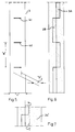
- Shown in Figure 1 is a portable display system which comprises six panels arranged in rows and columns.
- the panels, or elements, are mutually identical and it will be understood that, in practice, the display system need not be restricted to six panels but may comprise any number of panels of any desired outer shape. (See for instance Figure 8).
- FIG. 1 a panel 1 which is intended for a portable display system and then particularly for a display system of the kind which includes a plurality of panels or elements positioned side-by-side and edge-to-edge and mutually jointed by means of one or more hinges.
- Each panel 1 consists of a sheet or plate 10, 10' and the panels are mutually joined by means of an elongated, bendable device or hinge strip 3 which, in the present case, consists of a transparent adhesive tape, although other forms of tape and bands can be used.
- one and the same length of adhesive tape 3 extends from the upper part la of the panel 1 to its lower part 1b and forms a number of segments 31, 32, 33 therebetween.
- the hinge strip 3 comprises a strip of transparent adhesive tape 3 which is sufficiently strong to form a hinge between two mutually adjacent, flat panels 10, 10'.
- Figure 2a illustrates the principle of dividing the hinge strip 3 into a plurality of segments, although only three such segments 31, 32 and 33 are shown in the Figure.
- Each segment 31 has a non-adhesive first surface region 3A which is positioned between two adjacent adhesive second and third surface regions 31a and 31b, wherein a first surface region 3A of a segment 31 is positioned on one side, the left-hand side, of a rotational hinge line "V", whereas a first surface region 3B of an adjacent segment 32 is positioned on the other side, the right-hand side, of said hinge line "V" and is defined by second and third surface regions 32a and 32b respectively.
- the respective second and third surface regions 31a and 31b of a segment 31 are integrated with respective second and third surface regions 32a and 32b of an adjacent segment 32.
- Each of the two parallel outer margins 3a, 3b of the tape 3 shown in Figure 2b are coated with an adhesive layer 3a', 3b' on the surfaces that face towards the panels 10, 10', these adhesive layers being intended to fasten to the edge region of a respective panel 10, 10'.
- Figure 2b shows one such edge region 10a of the panel 10.
- a defined or limited part 3c having an adhesive layer 3c' is intended to fasten against the edge surface 10b of the panel 10.
- edge region 10a and/or the edge surface 10b of respective elements or panels with an adhesive layer and to fasten thereto a non-adhesive tape or like strip, and then particularly its outer extremities.
- the hinge strip or tape 3 has formed thereon a number of segment-separating weakenings 4, 4a, 4b, 4c and 4d which extend transversely to the longitudinal centre line or hinge line 3d of the tape.
- these weakenings consist of apertures, such as narrow slots, although it lies within the scope of the invention to perforate the tape or strip with apertures of other configurations.
- the weakenings are spaced apart at a predetermined distance "a".
- the weakenings are mutually equidistant and are spaced apart at a distance equal to seven times the thickness of the panel 10.
- a first, non-adhesive region 3A is positioned along the centre line 3d, or hinge line 3d, on one side of said line and extends between two weakenings 4b and 4c, said first region being intended to face towards the edge surface 10b of the first panel 10.
- This region 3A is displaced laterally relative to the rotational hinge line 3d and is followed by a second region 3B which is located between two weakenings 4c and 4d and which also extends along the centre line or hinge 3d but is offset relative to said line on the other side thereof.
- This second region 3B also lacks adhesive and is intended to face towards the edge surface 10b' of the second panel 10'.
- the weakenings 4c and 4d have an extension "b" across the tape 3 which is equal to or slightly greater than the total thickness of the two panels 10, 10'.
- the weakenings have also been given a transverse dimension which extends over 80% or less of the total width "c" of the tape.
- the distance between mutually adjacent weakenings 4c, 4d corresponds to more than three times the thickness of the panel 10.
- the tape 3 is applied simultaneously to two flat panels 10, 10' with said panels being located or positioned close together and with the edge surfaces 10b, 10b' located in one and the same plane P.
- a line 3d' is imprinted on the tape 3 and that when affixing the tape, said line is positioned in the defining surface between the panels 10 and 10' such as to form said rotational hinge line.
- the elongated, bendable device or hinge strip can be given an asymmetric construction, such that a centre line “C” will be located on one side of the hinge line "V".
- Figure 3 is a section view of the hinge strip, with Figure 3C showing the panels 10, 10' slightly displaced from one another, so as to show the features of the inventive hinge more clearly.
- the tape 3 is affixed to only one side of the panels and that when an adhesive part is fastened to one edge surface, an opposite part is not fastened to an opposing edge surface.
- the adhesive tape used may include different adhesive layers, from layers of strong adhesive to layers of weak adhesive.
- the regions 3A and 3B will extend along the edge region of the panels, such as the region 3A which extends some distance over the edge region 10a.
- the tape is configured in accordance with Figure 7, such that the panel surface of lower adhesion is covered with a broader adhesive layer 3b".
- inventive hinge is highly stable to forces which act in the directions F and F'in Figure 3C.
- Figure 3 illustrates the hinge which can be pivoted or rotated through more than 360°
- Figure 3A shows a tape 3 applied to two panels 10, 10' of equal thickness and positioned in accordance with Figure 4.
- Figure 3B shows the panel 10 rotated through 135° around a rotational axis "E” or "V".
- FIG. 3C shows the panels 10 and 10' in one and the same plane, although slightly separated for the purpose of illustration.
- Figure 3D illustrates the panel 10 rotated through a further 45° about a new further rotational axis "G" located on the rear side of the panels or on the side to which the tape is affixed.
- the panel 10 can be rotated further around the axis "G", to a position in which the panel is rotated through 360° in relation to the panel position shown in Figure 3A.
- Figure 8 illustrates a portable display system collapsed to form a package 20 and carrried by a person "M", the panels of said system having a slightly different shape from the panels illustrated in Figure 1.
- the collapsed system 20 can be extended to enable a picture or text to be shown on the ten panels included in the system, with said picture or text covering the panel joins.
- Some of the panels, 21-22, are positioned in a straight line, whereas the panels 23 and 24 are positioned in a convex, curved line.
- the panels 25 and 26 are positioned in a concave, curved line, whereas the panels 27, 28, 29 and 30 are positioned in a straight line.
- Each panel is joined to an adjacent panel by means of a hinge strip 3 and the panel joins are therewith practically unnoticeable.
- the panel joins are more noticeable in the case of those panels that are positioned along a convex, curved line.
- the panels 21-30 can be folded together in a zig-zag fashion to form the package 20.
- the backing or substrate material should be sufficiently thin, however, so as to give a distinctive fold and therewith form a hinge line.
- the embodiments shown have an end surface directed perpendicular to the planar surface of the panel it is obvious that said end surface can be formed with an other angle.
- the panels may be arranged in a curved pattern with end surfaces arranged adjacent each other and parallel to each other.
Landscapes
- Engineering & Computer Science (AREA)
- Architecture (AREA)
- Mechanical Engineering (AREA)
- Physics & Mathematics (AREA)
- Electromagnetism (AREA)
- Civil Engineering (AREA)
- Structural Engineering (AREA)
- Adhesive Tapes (AREA)
- Flexible Shafts (AREA)
- Laminated Bodies (AREA)
- Devices For Indicating Variable Information By Combining Individual Elements (AREA)
- Supports For Pipes And Cables (AREA)
- Adhesives Or Adhesive Processes (AREA)
- Containers And Plastic Fillers For Packaging (AREA)
- Structure Of Belt Conveyors (AREA)
- Finishing Walls (AREA)
Claims (9)
- Gelenkstreifen zur Bildung eines Gelenks zwischen zwei benachbarten Elementen, die normalerweise in Form von zwei flachen Tafeln vorliegen, wobei mindestens die äußeren Teile des Streifens mit einer jeweiligen Klebschicht beschichtet sind, um an einem Randbereich und/oder einer Randfläche eines jeweiligen Elements zu haften, oder als Alternative der Randbereich und/oder die Randfläche jeweiliger Elemente mit einer Klebschicht beschichtet sind, um an den äußeren Teilen des Streifens zu haften, dadurch gekennzeichnet, daß der Gelenkstreifen entlang seiner Randfläche (10b) in Segmente (31, 32) unterteilt ist; daß jedes Segment (31) einen ersten nicht haftenden Flächenbereich (3A) aufweist, der zwischen zwei benachbarten zweiten und dritten Flächenbereichen positioniert ist; und daß sich ein erster Flächenbereich (3A) eines Segments (31) auf einer Seite einer und benachbart einer Gelenklinie ("V") befindet, und daß sich ein erster Flächenbereich (3B) eines benachbarten Segments auf der anderen Seite der und benachbart der Gelenklinie ("V") befindet.
- Vorrichtung nach Anspruch 1, dadurch gekennzeichnet, daß die zweiten und dritten Segmentflächenbereiche mit zweiten und dritten Flächenbereichen eines benachbarten Segments integriert sind.
- Vorrichtung nach Anspruch 1 oder 2, gekennzeichnet durch mehrere voneinander beabstandete, segmenttrennende Schwächungen wie zum Beispiel Aussparungen, Schlitze, Lochungen oder dergleichen, die sich quer zu der sich in Längsrichtung erstreckenden Mittellinie oder Gelenkdrehlinie der länglichen Vorrichtung erstrecken; und dadurch gekennzeichnet, daß ein erster, sich zwischen zwei Schwächungen erstreckender und sich auf einer Seite der Linie befindender, nicht haftender Bereich seitlich zu einem zweiten, nicht haftenden Bereich eines zweiten Elementes, der sich zwischen zwei Schächungen erstreckt und sich auf der anderen Seite der Mittellinie oder Gelenkdrehlinie befindet, versetzt ist.
- Vorrichtung nach Anspruch 3, dadurch gekennzeichnet, daß die Schwächungen abstandsgleich entlang der Randfläche der gesamten Tafel oder des gesamten Elements beabstandet sind.
- Vorrichtung nach Anspruch 3, dadurch gekennzeichnet, daß die Schwächungen eine Quererstreckung aufweisen, die gleich der oder etwas größer als die Gesamtdicke der beiden Elemente ist.
- Vorrichtung nach Anspruch 3, dadurch gekennzeichnet, daß die Schwächungen eine Erstreckung aufweisen, die 80% oder weniger der Bandbreite bedecken.
- Vorrichtung nach Anspruch 3, dadurch gekennzeichnet, daß der Abstand zwischen benachbarten Schwächungen mehr als dem Dreifachen der Dicke des Elements entspricht.
- Vorrichtung nach Anspruch 1 oder 3, dadurch gekennzeichnet, daß die Vorrichtung an zwei flache Elemente angebracht wird, wobei die Elemente dicht beieinander angeordnet sind und sich die Randflächen der Elemente in ein und derselben Ebene befinden.
- Vorrichtung nach Anspruch 1 oder 3, dadurch gekennzeichnet, daß das Band mit einer Zentrierlinie oder dergleichen versehen ist.
Applications Claiming Priority (3)
| Application Number | Priority Date | Filing Date | Title |
|---|---|---|---|
| SE9002966 | 1990-09-18 | ||
| SE9002966A SE468565B (sv) | 1990-09-18 | 1990-09-18 | Bandformat boejbart organ |
| PCT/SE1991/000618 WO1992005331A1 (en) | 1990-09-18 | 1991-09-16 | An elongated bendable device |
Publications (2)
| Publication Number | Publication Date |
|---|---|
| EP0552182A1 EP0552182A1 (de) | 1993-07-28 |
| EP0552182B1 true EP0552182B1 (de) | 1996-01-17 |
Family
ID=20380387
Family Applications (1)
| Application Number | Title | Priority Date | Filing Date |
|---|---|---|---|
| EP91916933A Expired - Lifetime EP0552182B1 (de) | 1990-09-18 | 1991-09-16 | Längliche, biegbare vorrichtung |
Country Status (8)
| Country | Link |
|---|---|
| US (1) | US5355555A (de) |
| EP (1) | EP0552182B1 (de) |
| AT (1) | ATE133229T1 (de) |
| AU (1) | AU649273B2 (de) |
| CA (1) | CA2090674A1 (de) |
| DE (1) | DE69116562T2 (de) |
| SE (1) | SE468565B (de) |
| WO (1) | WO1992005331A1 (de) |
Families Citing this family (26)
| Publication number | Priority date | Publication date | Assignee | Title |
|---|---|---|---|---|
| US5492476A (en) * | 1994-06-08 | 1996-02-20 | Steelcase Inc. | Fold out display |
| US5960848A (en) * | 1997-12-22 | 1999-10-05 | Excel Packaging, Inc. | Portable display board |
| US8074324B2 (en) | 1999-11-09 | 2011-12-13 | Foster-Miller, Inc. | Flexible, deployment rate damped hinge |
| US6910304B2 (en) * | 2002-04-02 | 2005-06-28 | Foster-Miller, Inc. | Stiffener reinforced foldable member |
| US6719363B2 (en) * | 2002-09-12 | 2004-04-13 | Collins & Aikman Products Co. | Hinge apparatus for vehicle floor systems |
| US6799791B2 (en) * | 2002-12-19 | 2004-10-05 | Aerotail, Llc. | Deployable vehicle fairing structure |
| US6915611B2 (en) * | 2002-12-19 | 2005-07-12 | Aerotail, Llc | Deployable structure |
| US8393080B2 (en) | 2003-08-20 | 2013-03-12 | Hunter Douglas Inc. | Method for making a window covering having operable vanes |
| CN100518592C (zh) | 2003-08-20 | 2009-07-29 | 亨特道格拉斯有限公司 | 带有可折叠式叶片的可收起式遮帘 |
| KR101387049B1 (ko) * | 2004-08-20 | 2014-04-18 | 헌터더글라스인코포레이티드 | 작동가능한 베인을 갖는 윈도우 커버링 제조 장치 및 방법 |
| US20060101729A1 (en) * | 2004-11-17 | 2006-05-18 | Waters Michael A | Hinged panels for construction of a habitable building |
| US7304839B1 (en) * | 2006-01-26 | 2007-12-04 | James Burns | Outdoor laptop computer protector |
| US20080011430A1 (en) * | 2006-07-14 | 2008-01-17 | Ya Li Lin | Shade without threading cords |
| JP5174031B2 (ja) | 2006-11-14 | 2013-04-03 | アトランティウム テクノロジーズ エルティディ. | 光透過性導管を使用した液体消毒のための方法および装置 |
| US20080295876A1 (en) * | 2007-06-04 | 2008-12-04 | Michael Ouellette | Folding windscreen for ice fishing |
| US8261807B2 (en) | 2008-04-28 | 2012-09-11 | Hunter Douglas Inc. | Dual fabric covering for architectural openings |
| CA2722375C (en) | 2009-12-02 | 2019-06-11 | Hunter Douglas Inc. | Collapsible vane structure and related method for a shade for an architectural opening |
| US9089206B2 (en) * | 2010-03-05 | 2015-07-28 | Berrien Metal Products, Inc. | Portable podium |
| US9089205B2 (en) * | 2010-03-05 | 2015-07-28 | Berrien Metal Products, Inc. | Portable podium |
| WO2011119333A1 (en) | 2010-03-23 | 2011-09-29 | Hunter Douglas Inc. | System for biasing fabric to gather in predetermined direction |
| US8826495B2 (en) * | 2010-06-01 | 2014-09-09 | Intel Corporation | Hinged dual panel electronic device |
| US20110291964A1 (en) | 2010-06-01 | 2011-12-01 | Kno, Inc. | Apparatus and Method for Gesture Control of a Dual Panel Electronic Device |
| WO2013033010A1 (en) | 2011-08-26 | 2013-03-07 | Hunter Douglas Inc. | Double pleat cellular shade element |
| US20130196100A1 (en) * | 2012-01-26 | 2013-08-01 | Nike, Inc. | Three-Dimensional Bag With Affixed Seams |
| US8813448B1 (en) * | 2013-08-09 | 2014-08-26 | Karen Ann Rensi | Adjustable rigid corner bead |
| IT202100000080U1 (it) * | 2021-01-08 | 2022-07-08 | Andrea Favoni | Cerniera a doppio battente adesiva |
Family Cites Families (13)
| Publication number | Priority date | Publication date | Assignee | Title |
|---|---|---|---|---|
| US1196244A (en) * | 1916-05-12 | 1916-08-29 | Yokichi Kinoshita | Hinge structure for screen-sections. |
| US2096559A (en) * | 1935-11-02 | 1937-10-19 | Lester S Riley | Mounting hinge for cards, photographs, and the like |
| SE333523B (de) * | 1969-10-14 | 1971-03-15 | I Archenholtz | |
| DE2101526A1 (de) * | 1971-01-14 | 1972-07-27 | Archenholtz, Ingvar, Lomma (Schweden) | Scharnieranordnung |
| US3851353A (en) * | 1971-07-06 | 1974-12-03 | A Wakeman | Pliable tape structures |
| US3751760A (en) * | 1971-07-06 | 1973-08-14 | A Wakeman | Pliable tape structure |
| USRE28672E (en) * | 1971-07-06 | 1976-01-06 | Pliable tape structure | |
| US3913656A (en) * | 1973-01-24 | 1975-10-21 | Reynolds Guyer | Hinged panels |
| US3925136A (en) * | 1973-07-16 | 1975-12-09 | Alfred W Wakeman | Method of making pliable tape structures |
| FR2339724A1 (fr) * | 1976-01-30 | 1977-08-26 | Breteche Serge | Dispositif de liaison pivotante entre deux panneaux |
| SE437056B (sv) * | 1982-10-01 | 1985-02-04 | Ahlberg Beckrot Ytter Ab | Gangled |
| SE437053B (sv) * | 1983-05-11 | 1985-02-04 | Fixfabriken Ab | Anordning vid las |
| AU1591188A (en) * | 1987-04-10 | 1988-11-04 | Ahlberg & Co. A.B. | Buildable device |
-
1990
- 1990-09-18 SE SE9002966A patent/SE468565B/sv not_active IP Right Cessation
-
1991
- 1991-09-16 EP EP91916933A patent/EP0552182B1/de not_active Expired - Lifetime
- 1991-09-16 CA CA002090674A patent/CA2090674A1/en not_active Abandoned
- 1991-09-16 AU AU86190/91A patent/AU649273B2/en not_active Ceased
- 1991-09-16 AT AT91916933T patent/ATE133229T1/de not_active IP Right Cessation
- 1991-09-16 WO PCT/SE1991/000618 patent/WO1992005331A1/en not_active Ceased
- 1991-09-16 DE DE69116562T patent/DE69116562T2/de not_active Expired - Fee Related
- 1991-09-16 US US07/983,850 patent/US5355555A/en not_active Expired - Fee Related
Also Published As
| Publication number | Publication date |
|---|---|
| WO1992005331A1 (en) | 1992-04-02 |
| SE468565B (sv) | 1993-02-08 |
| DE69116562T2 (de) | 1996-09-19 |
| US5355555A (en) | 1994-10-18 |
| EP0552182A1 (de) | 1993-07-28 |
| ATE133229T1 (de) | 1996-02-15 |
| AU649273B2 (en) | 1994-05-19 |
| CA2090674A1 (en) | 1992-03-19 |
| AU8619091A (en) | 1992-04-15 |
| SE9002966D0 (sv) | 1990-09-18 |
| SE9002966L (sv) | 1992-03-19 |
| DE69116562D1 (de) | 1996-02-29 |
Similar Documents
| Publication | Publication Date | Title |
|---|---|---|
| EP0552182B1 (de) | Längliche, biegbare vorrichtung | |
| US4233767A (en) | Kit for making a multiple view pictorial display device | |
| US4163303A (en) | Hinge structure | |
| US4194313A (en) | Articulated panel display | |
| US7958679B2 (en) | Variable connectors for angling modular wall systems | |
| AU2003264650B2 (en) | Architectural panel | |
| NL8802915A (nl) | Demontabele wand- of plafondkonstruktie, vrijdragend rechthoekig paneel voor een wand- of plafondbekleding en werkwijze voor het vervaardigen daarvan. | |
| JPH02289392A (ja) | アルバム | |
| JP2513389Y2 (ja) | 貼り合せ式両面ラベル | |
| WO2005062921A2 (en) | Craft set and elements for constructing pop-up cards | |
| US3643393A (en) | Building construction | |
| US5221396A (en) | Method of mass manufacture of rigid display sign | |
| JPS6033020Y2 (ja) | アルバム台紙 | |
| JP3391612B2 (ja) | 金属板を備えた目地部材 | |
| US5096758A (en) | Rigid display sign | |
| JP2001096652A (ja) | 加工化粧板とその製造方法 | |
| JPH03138198A (ja) | アルバム用台紙の製造方法 | |
| JP2553620Y2 (ja) | 銅葺屋根の接合構造 | |
| JPH0941586A (ja) | 防水シート接合固定構造 | |
| US3207199A (en) | Method of and means for joining sheets together | |
| JPH077453Y2 (ja) | 天井仕上材 | |
| JP2003170690A (ja) | 複数枚で1セットのインデックス及びその貼着方法 | |
| NL8802386A (nl) | Vrijdragend rechthoekig paneel voor een wand- of plafondbekleding. | |
| JPH08151766A (ja) | タイルユニット | |
| JPH0518149A (ja) | 門回り部材 |
Legal Events
| Date | Code | Title | Description |
|---|---|---|---|
| PUAI | Public reference made under article 153(3) epc to a published international application that has entered the european phase |
Free format text: ORIGINAL CODE: 0009012 |
|
| 17P | Request for examination filed |
Effective date: 19930330 |
|
| AK | Designated contracting states |
Kind code of ref document: A1 Designated state(s): AT BE CH DE DK ES FR GB GR IT LI LU NL SE |
|
| 17Q | First examination report despatched |
Effective date: 19941223 |
|
| GRAA | (expected) grant |
Free format text: ORIGINAL CODE: 0009210 |
|
| AK | Designated contracting states |
Kind code of ref document: B1 Designated state(s): AT BE CH DE DK ES FR GB GR IT LI LU NL SE |
|
| PG25 | Lapsed in a contracting state [announced via postgrant information from national office to epo] |
Ref country code: IT Free format text: LAPSE BECAUSE OF FAILURE TO SUBMIT A TRANSLATION OF THE DESCRIPTION OR TO PAY THE FEE WITHIN THE PRE;WARNING: LAPSES OF ITALIAN PATENTS WITH EFFECTIVE DATE BEFORE 2007 MAY HAVE OCCURRED AT ANY TIME BEFORE 2007. THE CORRECT EFFECTIVE DATE MAY BE DIFFERENT FROM THE ONE RECORDED.SCRIBED TIME-LIMIT Effective date: 19960117 Ref country code: DK Effective date: 19960117 Ref country code: BE Effective date: 19960117 Ref country code: NL Free format text: LAPSE BECAUSE OF FAILURE TO SUBMIT A TRANSLATION OF THE DESCRIPTION OR TO PAY THE FEE WITHIN THE PRESCRIBED TIME-LIMIT Effective date: 19960117 Ref country code: GR Free format text: LAPSE BECAUSE OF FAILURE TO SUBMIT A TRANSLATION OF THE DESCRIPTION OR TO PAY THE FEE WITHIN THE PRESCRIBED TIME-LIMIT Effective date: 19960117 Ref country code: AT Effective date: 19960117 Ref country code: ES Free format text: THE PATENT HAS BEEN ANNULLED BY A DECISION OF A NATIONAL AUTHORITY Effective date: 19960117 |
|
| REF | Corresponds to: |
Ref document number: 133229 Country of ref document: AT Date of ref document: 19960215 Kind code of ref document: T |
|
| REF | Corresponds to: |
Ref document number: 69116562 Country of ref document: DE Date of ref document: 19960229 |
|
| REG | Reference to a national code |
Ref country code: CH Ref legal event code: NV Representative=s name: E. BLUM & CO. PATENTANWAELTE |
|
| PG25 | Lapsed in a contracting state [announced via postgrant information from national office to epo] |
Ref country code: SE Effective date: 19960417 |
|
| ET | Fr: translation filed | ||
| NLV1 | Nl: lapsed or annulled due to failure to fulfill the requirements of art. 29p and 29m of the patents act | ||
| PG25 | Lapsed in a contracting state [announced via postgrant information from national office to epo] |
Ref country code: LU Free format text: LAPSE BECAUSE OF NON-PAYMENT OF DUE FEES Effective date: 19960930 |
|
| PLBE | No opposition filed within time limit |
Free format text: ORIGINAL CODE: 0009261 |
|
| STAA | Information on the status of an ep patent application or granted ep patent |
Free format text: STATUS: NO OPPOSITION FILED WITHIN TIME LIMIT |
|
| 26N | No opposition filed | ||
| PGFP | Annual fee paid to national office [announced via postgrant information from national office to epo] |
Ref country code: GB Payment date: 19970916 Year of fee payment: 7 |
|
| PGFP | Annual fee paid to national office [announced via postgrant information from national office to epo] |
Ref country code: CH Payment date: 19970923 Year of fee payment: 7 |
|
| PGFP | Annual fee paid to national office [announced via postgrant information from national office to epo] |
Ref country code: FR Payment date: 19970929 Year of fee payment: 7 |
|
| PG25 | Lapsed in a contracting state [announced via postgrant information from national office to epo] |
Ref country code: GB Free format text: LAPSE BECAUSE OF NON-PAYMENT OF DUE FEES Effective date: 19980916 |
|
| PG25 | Lapsed in a contracting state [announced via postgrant information from national office to epo] |
Ref country code: LI Free format text: LAPSE BECAUSE OF NON-PAYMENT OF DUE FEES Effective date: 19980930 Ref country code: CH Free format text: LAPSE BECAUSE OF NON-PAYMENT OF DUE FEES Effective date: 19980930 |
|
| GBPC | Gb: european patent ceased through non-payment of renewal fee |
Effective date: 19980916 |
|
| REG | Reference to a national code |
Ref country code: CH Ref legal event code: PL |
|
| PG25 | Lapsed in a contracting state [announced via postgrant information from national office to epo] |
Ref country code: FR Free format text: LAPSE BECAUSE OF NON-PAYMENT OF DUE FEES Effective date: 19990531 |
|
| REG | Reference to a national code |
Ref country code: FR Ref legal event code: ST |
|
| PGFP | Annual fee paid to national office [announced via postgrant information from national office to epo] |
Ref country code: DE Payment date: 20000915 Year of fee payment: 10 |
|
| PG25 | Lapsed in a contracting state [announced via postgrant information from national office to epo] |
Ref country code: DE Free format text: LAPSE BECAUSE OF NON-PAYMENT OF DUE FEES Effective date: 20020501 |