EP0548044A1 - Rail vehicle - Google Patents
Rail vehicle Download PDFInfo
- Publication number
- EP0548044A1 EP0548044A1 EP92890267A EP92890267A EP0548044A1 EP 0548044 A1 EP0548044 A1 EP 0548044A1 EP 92890267 A EP92890267 A EP 92890267A EP 92890267 A EP92890267 A EP 92890267A EP 0548044 A1 EP0548044 A1 EP 0548044A1
- Authority
- EP
- European Patent Office
- Prior art keywords
- bogie
- car body
- supported
- bridge
- rail vehicle
- Prior art date
- Legal status (The legal status is an assumption and is not a legal conclusion. Google has not performed a legal analysis and makes no representation as to the accuracy of the status listed.)
- Granted
Links
Images


Classifications
-
- B—PERFORMING OPERATIONS; TRANSPORTING
- B61—RAILWAYS
- B61D—BODY DETAILS OR KINDS OF RAILWAY VEHICLES
- B61D13/00—Tramway vehicles
-
- B—PERFORMING OPERATIONS; TRANSPORTING
- B61—RAILWAYS
- B61F—RAIL VEHICLE SUSPENSIONS, e.g. UNDERFRAMES, BOGIES OR ARRANGEMENTS OF WHEEL AXLES; RAIL VEHICLES FOR USE ON TRACKS OF DIFFERENT WIDTH; PREVENTING DERAILING OF RAIL VEHICLES; WHEEL GUARDS, OBSTRUCTION REMOVERS OR THE LIKE FOR RAIL VEHICLES
- B61F5/00—Constructional details of bogies; Connections between bogies and vehicle underframes; Arrangements or devices for adjusting or allowing self-adjustment of wheel axles or bogies when rounding curves
- B61F5/02—Arrangements permitting limited transverse relative movements between vehicle underframe or bolster and bogie; Connections between underframes and bogies
- B61F5/14—Side bearings
- B61F5/148—Side bearings between bolsterless bogies and underframes
Definitions
- the invention relates to a rail vehicle, in particular a low-floor vehicle, e.g. for local transport, such as trams and the like, with a plurality of car bodies which can be pivoted relative to one another, each of which is supported on a, in particular cradle-less, bogie by means of secondary springs, the wheels of which are possibly driven, the wheels of the bogie on the bogie frame, in particular via a swing arm each , are mounted and a coupling device is provided for connecting the bogie frame to the car body and between two car bodies each supported on a bogie, a bridge designed as a floating car bodies is arranged, which is supported by one of two joints spaced apart in the vehicle longitudinal direction with the neighboring, supported Car body is coupled.
- trams and light rail vehicles are preferably of low-floor design, with only one step to be overcome compared to three or more steps in the case of conventional vehicles when boarding and alighting.
- the aim is to avoid platforms on the inside of the car.
- the car body makes the movement of the bogie as it enters a curve, provided that the bogie is rigidly connected to this car body.
- the spontaneous rotation of the car body, which occurs here, is undoubtedly registered by the passengers.
- the rail vehicle according to the invention has high driving comfort due to the damping of the transverse movements of the car body.
- "real" bogies with wheel axles that are always parallel to each other, at a small mutual distance of, for example, 1.8 to 2 m), which allow the bogie to be unscrewed from under the body, the transmission to the body is delayed, so do the managers reduced at the starting wheel sets. This also increases driving comfort and reduces wheel-rail wear.
- the car body having counter stops, which limit the relative pivoting between the bogie and car body with the stops arranged on the cross bridge, in particular the buffers, cooperate, it is ensured that the bogie comes to the side of the car body only after a certain rotation (about 2 °) via the buffer.
- the transverse spring characteristic is therefore non-linear.
- the coupling device for the longitudinally rigid connection has spring assemblies, the axes of which extend essentially in the longitudinal direction of the vehicle and which each have one end on the body and the other end are supported on the bogie frame.
- the springs extending in the longitudinal direction of the vehicle hinder transverse and rotational movements of the car body relative to the bogie with only small restoring forces.
- a further embodiment of the subject matter of the invention provides that the coupling device is designed as a link connection and that this link connection has a two-armed connection Has lever, which is preferably pivotally connected to the center of the car body, in particular with a longitudinal member of the car body or with the cross bridge connecting the two longitudinal members of the bogie frame, wherein in the area of each end of the two-armed lever a handlebar engages, which with its from the two-armed Lever remote end engages on the cross bridge or in the case of the two-armed lever on the cross bridge, is articulated to the body.
- a handlebar engages, which with its from the two-armed Lever remote end engages on the cross bridge or in the case of the two-armed lever on the cross bridge, is articulated to the body.
- the two-armed lever pivotally connected to the longitudinal member of the car body passes through a transverse slot in the car body and is preferably connected to the car body or its longitudinal member via a vertical axis.
- additional springs acting transversely to the longitudinal direction of the vehicle can be provided. These springs can be arranged centrally symmetrically between the cross bridge of the bogie frame and the body.
- the two-armed lever can be supported by spring packs on the bogie frame, in particular on its cross bridge, to support the flexicoil effect of the secondary suspension with a pure rotary movement between the bogie and car body.
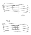
- the need for envelope space in curves is favorably influenced if, in a manner known per se, the length of the bridge is at most equal to the length of the adjacent supported car body.
- the aforementioned configuration makes it possible to keep the envelope space small.
- each wheel arch is arranged under two rows of pairs of seats facing one another with their backrests and laterally adjacent to one another. This enables the low-floor floor to be arranged around the wheel arches without platforms.
- a train can be assembled modularly, the sum of the number of supported and the number of floating car bodies being an odd number, in particular 3.5 or 7.
- the smallest basic unit is a vehicle consisting of three car bodies, namely two supported and one floating car body, which is arranged between the two supported car bodies.
- the joints between the floating car body and each of the adjacent car bodies are designed as tannin joints, at In longer vehicles, the other joints are alternately designed as a tanner's joint and as a simple joint, so that changes in inclination that occur in the course of the track and their transitional roundings can be easily negotiated.
- 1 and 2 car bodies are designated, which are pivotable against each other.
- the car body 1 is one which is arranged at the ends of the rail vehicle, whereas the car body designated by 2 is arranged between the terminal car body 1.
- Each of the swiveling car bodies 1, 2 is supported on a bogie 4 which is cradle-free in the exemplary embodiment shown.
- the wheels 5 of the bogie can be driven, but bogies with non-driven wheels 5 are also possible.
- the wheels 5 of the bogie 4 are mounted on a cross bridge 6 of the bogie frame, in particular in rockers 7 (FIGS. 20, 24).
- the swing arm bearing is designated 22.
- a coupling device designated 8 is provided in the drawing.
- a bridge 3 is arranged, which is designed as a floating car body and in each case via one of two joints 9 spaced apart in the longitudinal direction of the vehicle with the adjacent car bodies 1, 2, each supported on a bogie is coupled.
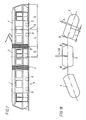
- Fig. 1 the smallest basic unit of a rail vehicle is shown, which consists of a total of three car bodies, namely two terminal car body 1 and a car body 3 located in between.
- the joints 9 are designed in such a basic unit as Gerber joints and form a vertical axis of rotation and moments take up around the lateral axis.
- FIG. 2 illustrates in more detail, the system is modular, so that rail vehicles consisting of five, seven and multi-car bodies are possible, as illustrated in FIGS. 3-5 and 16 and 17.
- the hinge 9 is shown symbolically in the drawings only by the bellows-like outer lining.
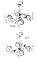
- the drive is preferably carried out via wheel hub motors 23, which can be designed as three-phase asynchronous motors, via planetary gears 24 directly onto the wheels 5.
- wheel hub motors 23 can be designed as three-phase asynchronous motors, via planetary gears 24 directly onto the wheels 5.
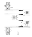
- This compact arrangement allows the drive to be located directly under adjacent wheel housings 20 (FIG 27-29), the seats with their backrests 21 being arranged dos-a-dos on each box 12 without the need to provide platforms in the passenger compartment. This way it is possible to get one through reaching low floor height of approx.
- FIGS. 28 and 29 show that the seat arrangement is identical to that even with a narrow track up to 900 mm track width Seat arrangement for cars for standard gauge, however the bogie frame for narrow gauge is narrower than for standard gauge.
- the length of the bridge 3 is at most equal to the length of the car bodies 1 and 2, which are adjacent to it in the rail vehicle and supported on the bogies, if the requirement for a small envelope space is required.
- the envelope is designated 33.
- connection of the car body to the bogie which can be seen in principle from FIG. 15.
- 14 shows a further embodiment based on the principle.
- the connection is transverse and torsionally flexible due to the flexicoil effect of the secondary suspension, which supports the car body on the bogie frame.
- the double arrow D indicates the torsional elasticity and the double arrow Q the transverse elasticity. This can be supported by additional transverse spring elements, as shown in FIGS. 21, 22. Stops are provided to limit the angle of rotation or transverse movements.
- connection of the car body to the bogie must be longitudinally rigid or longitudinally rigid, as will be explained below.
- the coupling device between the car bodies 1 and 2 and the cross bridge 6 of the bogie frame has spring assemblies 10 and 11, the axes of which essentially extend in the longitudinal direction of the vehicle and each end with one end against the car bodies 1 and 2 and are supported at the other end on the cross bridge 6. 23 and 24, only the side member 15 of the car body 1 is shown.
- the coupling between the bogie 4 and the body 1 is longitudinally rigid for absorbing braking and acceleration forces, but - as will be explained later - also transverse and torsionally elastic.
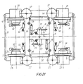
- 19 to 21 show arrangements in which the coupling device is designed as a link connection to achieve a longitudinally rigid connection of the bogie frame to the car body.
- the coupling device 8 is designed as an articulated parallelogram.
- the bearings 12 of the handlebars 25 of the quadrangle forming the cranks are arranged on the cross bridge 6 essentially symmetrically to the longitudinal center plane.
- the coupling of the articulated parallelogram, which forms a two-armed lever 13 passes through a transverse slot 14 in the longitudinal member 15 and thus also in the car body 1, 2.
- the two-armed lever 13 is via a vertical axis 16 which is centered between the bearings 17 in the two-armed lever 13 of the handlebars 25 is arranged, connected to the longitudinal beam U of the car body 1 or 2.
- stops 18 designed as buffers are arranged symmetrically to the longitudinal center plane of the bogie 4.
- the car body 1 or 2 has counter stops 19 which cooperate with the stops arranged on the cross bridge 6, in particular the buffers 18, to limit the relative pivoting between the bogie 4 and the car body 1 or 2.
- Fig. 26 clearly shows that in the deflected state the car body 1 abuts one of the counter stops 19 on a buffer 18.
- the buffers 18 limit both the transverse movement of the car body 1 or 2 with respect to the bogie 4 and the turning of the bogie 4 with respect to the car body 1 or 2.
- the suspension of the car body 1 or 2 against the bogie 4 takes place via primary and secondary springs .
- the primary suspension is designed as a rubber spring 26.
- the secondary suspension can be made of steel or rubber or as an air spring. It is designated 27.
- a vertical damper 28 is arranged parallel to each spring column of the secondary spring 27.
- each bogie is also provided with two magnetic rail brakes 30.
- the cross bridge 6 is torsionally soft (X- or H-shaped) in order to compensate for torsion that occurs when driving on a ramp (elevation in Vignol tracks) or with track position errors, so that no significantly different wheel loads occur.
- the wheel hub motors 23 are connected by track holding rods 31, which can simultaneously serve as track clearers and can ensure the exact observance of the track dimension in all operating states art to perform the relevant function of a wheelset shaft, which is not present in the bogies shown.
- the two-armed lever 13 is mounted centrally in the H-shaped cross bridge 6 in this embodiment.
- the handlebars 25 mounted in the bearings 17 at the two ends of the two-armed lever 13 are each mounted on the car body at their end remote from the bearing 17.
- the links 25 extend in opposite directions away from the two-armed lever 13.
- additional springs 40 are provided, which are arranged essentially transversely to the longitudinal direction of the vehicle.
- FIG. 22 An embodiment of such a spring can be seen in FIG. 22.
- the spring plates are labeled 41.42.
- the compression of the spring and thus also the transverse or rotational movement of the body 1 relative to the bogie 4 is limited by a stop 43 which cooperates with a rubber buffer 44.
- the rubber buffer 44 protrudes from the cover 47 into the interior of a housing 48, the bottom of which is formed by one of the spring plates 41.
- the spring plate 41 guides a piston 49 passing through the spring, to which the stop 43 is fastened, preferably by means of screws 50.
- the piston 49 has at its free end remote from the stop 43 a bearing bore 45 for connection to the car body or the cross bridge, whereas the spring 40 is connected to the cross bridge or the car body by means of a pin (not shown), which is a Bearing hole 46 passes through in a tab 51 connected to the cover 47 of the housing 48.
- the two-armed lever 13 can, but does not have to be supported on the cross bridge 6 via spring assemblies 47 (rubber / metal springs). These spring assemblies result in an additional torsion spring, which supports the flexicoil effect of the secondary suspension 27 with a pure rotational movement of the bogie relative to the car body.
- the arrangement of the spring assemblies 47 is such that when rotating - depending on the direction of rotation - only one spring assembly is subjected to pressure.
- the brake disks are designated, which are within the track gauge in normal gauge (Fig. 19, 20 and 23 - 26, 28), but are arranged outside the track gauge in narrow gauge (Fig. 29).
Abstract
Description
Die Erfindung betrifft ein Schienenfahrzeug, insbesondere Niederflurfahrzeug, z.B. für den Nahverkehr, wie Straßenbahn u.dgl., mit mehreren gegeneinander schwenkbaren Wagenkasten, deren jeder an einem, insbesondere wiegenlosen, Drehgestell mittels Sekundärfedern abgestützt ist, dessen Räder gegebenenfalls angetrieben sind, wobei die Räder des Drehgestells am Drehgestellrahmen, insbesondere über je eine Schwinge, gelagert sind und eine Koppeleinrichtung zur Verbindung des Drehgestellrahmens mit dem Wagenkasten vorgesehen ist und zwischen zwei je an einem Drehgestell abgestützten Wagenkasten, eine als schwebender Wagenkästen ausgebildete Brücke angeordnet ist, die je über eines von zwei in Fahrzeuglängsrichtung voneinander beabstandeten Gelenken mit den benachbarten, abgestützten Wagenkasten gekuppelt ist.The invention relates to a rail vehicle, in particular a low-floor vehicle, e.g. for local transport, such as trams and the like, with a plurality of car bodies which can be pivoted relative to one another, each of which is supported on a, in particular cradle-less, bogie by means of secondary springs, the wheels of which are possibly driven, the wheels of the bogie on the bogie frame, in particular via a swing arm each , are mounted and a coupling device is provided for connecting the bogie frame to the car body and between two car bodies each supported on a bogie, a bridge designed as a floating car bodies is arranged, which is supported by one of two joints spaced apart in the vehicle longitudinal direction with the neighboring, supported Car body is coupled.
In den letzten Jahren wird aus umweltschonenden und energetischen Gründen dem schienengebundenen, öffentlichen Verkehr, insbesondere dem Nahverkehr, großes Interesse gewidmet. Aufgrund höheren Komfortanspruches der Fahrgäste werden Straßen- und Stadtbahnen bevorzugt in Niederflurbauart ausgeführt, wobei beim Ein- und Aussteigen lediglich eine einzige Stufe gegenüber drei oder mehr Stufen bei bisnun üblichen Fahrzeugen zu überwinden ist. Angestrebt wird die Vermeidung von Podesten im Inneren des Wagens.In recent years, great interest has been devoted to rail-bound public transport, especially local transport, for environmentally friendly and energetic reasons. Due to the higher comfort requirements of the passengers, trams and light rail vehicles are preferably of low-floor design, with only one step to be overcome compared to three or more steps in the case of conventional vehicles when boarding and alighting. The aim is to avoid platforms on the inside of the car.
Die Aufgabe, Fahrzeuge in Niederflurbauart zu entwickeln, führt zu neuen Fahrzeugkonfigurationen. Das in Mitteleuropa seit Mitte der 50er Jahre existierende Fahrzeugkonzept (Drehgestell unter den Wagenkastengelenken) führte bei Niederflurausführungen zu geringen Fahrwerksabständen. Drehgestelle haben sich für die Spurführung als gut erwiesen, mußten allerdings wegen der engen zu befahrenden Bögen in den bestehenden Nahverkehrsnetzen in geringen gegenseitigen Abständen angeordnet werden. Die geringe Entfernung wardaher nicht durch die maximal zulässige Achslast bedingt. Durch die geringe Fußbodenhöhe über dem Schienenniveau ragt bei Niederflurausführungen jedes Fahrwerk in den Fahrgastraum hinein und unterteilt diesen durch häufig nicht zu verdeckende Radkästen, Portale oder dergleichen.The task of developing low-floor vehicles leads to new vehicle configurations. The vehicle concept (bogie under the body joints) that had existed in Central Europe since the mid-1950s led to low chassis spacing for low-floor versions. Bogies have proven to be good for lane guidance, but had to be arranged close to one another in the existing local transport networks because of the narrow arches to be traveled. The short distance was therefore not due to the maximum permissible axle load. Due to the low floor height above the rail level, each landing gear protrudes into the passenger compartment in the low-floor version and divides it by frequently not concealing wheel arches, portals or the like.
Aus den vorerwähnten Umständen heraus wurden selbstlenkende Einzelachsfahrwerke mit Losrädern entwickelt. Damit wurde ein geringer Platzbedarf und eine größtmögliche Ausnutzung der zulässigen Achslast gewährleistet. Diese Selbstlenkung existiert zur Zeit unangetrieben, angetrieben allerdings nur bei Prototypen. Die fehlende Betriebserfahrung und Probleme mit der Antreibbarkeit haben zu einer gewissen Skepsis bei zahlreichen Nahverkehrsbetrieben geführt.Self-steering single-axle bogies with idler gears were developed based on the above-mentioned circumstances. This ensured a small footprint and the greatest possible utilization of the permissible axle load. This self-steering currently does not exist, but is only driven by prototypes. The lack of operational experience and problems with driveability have led to a certain degree of skepticism among numerous local transport companies.
Drehgestelle hingegen haben sich generell gut bewährt. Um solche Fahrwerke für Niederflurausführungen verwenden zu können, mußten einerseits Losräder verwendet werden, anderseits mußte eine Fahrzeugkonfiguration gefunden werden, die einen großen Fahrwerksabstand in Längsrichtung des Fahrzeuges erlaubt.Bogies, on the other hand, have generally proven their worth. In order to be able to use such trolleys for low-floor designs, loose wheels had to be used on the one hand, and on the other hand a vehicle configuration had to be found which allowed a large chassis distance in the longitudinal direction of the vehicle.
Dies verwirklichte man erstmals durch das sogenannte Gelenksteuerprinzip, bei dem ein Drehgestell mittig unter dem Wagenkasten angeordnet wird und zwei benachbarte Wagenkästen durch ein biegesteifes Vertikalgelenk verbunden werden. Dadurch kann bei einem Fahrzeug mit zwei Wagenkästen, gegenüber dem in Mitteleuropa üblichen Konzept, ein Drehgestell pro zwei Wagenkästen eingespart werden. Dieses Konzept ist modular auf drei, vier oder mehr Wagenkästen erweiterbar. Während der Kreisbogenfahrt eines nach dem Gelenkssteuerprinzip zusammengestellten Zuges stehen alle Drehgestelle radial. Dabei existiert kein Relativwinkel zwischen dem Drehgestell und dem diesem zugeordneten Wagenkasten. Bei Krümmungsänderung dreht das Drehgestell aus. Die Rückstellung des Drehgestells erfolgt durch bekannte Flexicoilwirkung der Sekundärfederung. Dieses Rückstellmoment ist auch zur Sicherstellung eines stabilen Geradeauslaufes notwendig. Das erwähnte Fahrzeugkonzept ist nur für relativ langsame Schienenfahrzeuge bis zu einer Höchstgeschwindigkeit von 100 km/h geeignet.This was realized for the first time by the so-called articulation control principle, in which a bogie is arranged centrally under the car body and two adjacent car bodies are connected by a rigid vertical joint. In this way, in a vehicle with two car bodies, one bogie can be saved per two car bodies compared to the concept common in Central Europe. This concept can be modularly expanded to three, four or more car bodies. During the circular arc of a train based on the joint control principle, all bogies are radial. There is no relative angle between the bogie and the car body assigned to it. If the bend changes, the bogie turns out. The bogie is reset by the known flexicoil effect of the secondary suspension. This restoring torque is also necessary to ensure stable straight running. The vehicle concept mentioned is only suitable for relatively slow rail vehicles up to a maximum speed of 100 km / h.
Der Nachteil dieser Konfiguration liegt in dem bei klassischen Straßenbahnnetzen erforderlichen relativ großen Ausdrehwinkel des Drehgestells, der wiederum einen großen Hüllraumbedarf erfordert, der mit steigender Zahl an Wagenkasten steigt. Überdies wird über den Fahrwerken, durch den großen Ausdrehwinkel des Drehgestells, zwischen den Rädern des Drehgestells vorhandener Durchgangsraum für die Fahrgäste stark eingeschränkt.The disadvantage of this configuration lies in the relatively large turning angle of the bogie required in classic tram networks, which in turn requires a large envelope space, which increases with an increasing number of car bodies. In addition, the passage space for the passengers between the wheels of the bogie is severely restricted above the running gears by the large turning angle of the bogie.
Bei einem Schienenfahrzeug der eingangs erwähnten Art (mit schwebender Brücke) macht der Wagenkasten ab Einfahrt in eine Kurve die Bewegung des Drehgestells mit, soferne dieses drehstarr mit diesem Wagenkasten verbunden ist. Die spontane Drehung des Wagenkastens, die hiebei auftritt, wird von den Fahrgästen unangenehm registriert.In the case of a rail vehicle of the type mentioned at the outset (with a floating bridge), the car body makes the movement of the bogie as it enters a curve, provided that the bogie is rigidly connected to this car body. The spontaneous rotation of the car body, which occurs here, is unpleasantly registered by the passengers.
Diesem Nachteil zu begegnen, ist eines der Ziele der Erfindung. Dies wird erreicht, wenn bei einem Fahrzeug der eingangs genannten Art, der Wagenkasten mittels der Sekundärfedern aufgrund deren Flexicoilwirkung quer- und drehelastisch am Drehgestellrahmen abgefedert ist und wenn in an sich bekannter Weise die unter dem Einfluß der Flexicoilwirkung der Sekundärfederung stehende Relativschwenkung zwischen Drehgestell und Wagenkasten begrenzt ist, wobei mit dem Drehgestellrahmen insbesondere als Puffer ausgebildete Anschläge verbunden sind, die mit Gegenanschlägen am Wagenkasten zusammenwirken, und wenn schließlich die Koppeleinrichtung den Wagenkasten längssteif oder längsstarr mit dem Drehgestell verbindet.Addressing this disadvantage is one of the aims of the invention. This is achieved when, in a vehicle of the type mentioned, the car body is cushioned by means of the secondary springs due to their flexicoil effect on the bogie frame in a transversely and torsionally elastic manner and if, in a manner known per se, the relative pivoting between the bogie and the car body under the influence of the flexicoil effect of the secondary suspension is limited, with the bogie frame, in particular, stops connected as buffers, which cooperate with counter-stops on the car body, and when the coupling device finally connects the car body in a longitudinally rigid or longitudinally rigid manner to the bogie.
Das erfindungsgemäße Schienenfahrzeug weist dabei durch die Dämpfung der Querbewegungen des Wagenkastens hohen Fahrkomfort auf. Durch den Einsatz "echter" Drehgestelle (mit ständig zueinander parallelen Radachsen, in geringem gegenseitigem Abstand von z.B. 1,8 bis 2 m), die eine Ausdrehbewegung des Drehgestelles unter dem Wagenkasten zulassen, deren Übertragung auf den Wagenkasten verzögert erfolgt, werden auch die Führungskräfte an den anlaufenden Radsätzen vermindert. Dies erhöht ebenfalls den Fahrkomfort und vermindert den Rad-Schienen Verschleiß. Durch die Anordnung von insbes. als Puffer ausgebildeten Anschlägen an der Querbrücke des Drehgestellrahmens, symmetrisch zur Längsmittenebene des Drehgestells, wobei der Wagenkasten Gegenanschläge aufweist, die zur Begrenzung der Relativschwenkung zwischen Drehgestell und Wagenkasten mit den an der Querbrücke angeordneten Anschlägen, insbes. den Puffern, zusammenwirken, wird sichergestellt, daß das Drehgestell erst nach einer bestimmten Drehung (etwa 2°) über die Puffer seitlich zur Anlage am Wagenkasten kommt. Die Querfedercharakterstik ist damit nichtlinear.The rail vehicle according to the invention has high driving comfort due to the damping of the transverse movements of the car body. Through the use of "real" bogies (with wheel axles that are always parallel to each other, at a small mutual distance of, for example, 1.8 to 2 m), which allow the bogie to be unscrewed from under the body, the transmission to the body is delayed, so do the managers reduced at the starting wheel sets. This also increases driving comfort and reduces wheel-rail wear. Due to the arrangement of stops, in particular designed as buffers, on the cross bridge of the bogie frame, symmetrical to the longitudinal center plane of the bogie, the car body having counter stops, which limit the relative pivoting between the bogie and car body with the stops arranged on the cross bridge, in particular the buffers, cooperate, it is ensured that the bogie comes to the side of the car body only after a certain rotation (about 2 °) via the buffer. The transverse spring characteristic is therefore non-linear.
In weiterer Ausgestaltung des Erfindungsgegenstandes kann vorgesehen werden, daß bei längssteifer Ausbildung der Verbindung zwischen Wagenkasten und Drehgestell, die Koppeleinrichtung für die längssteife Verbindung Federpakete aufweist, deren Achsen sich im wesentlichen in Fahrzeuglängsrichtung erstrecken und die jeweils mit einem Ende am Wagenkasten und mit dem anderen Ende am Drehgestellrahmen abgestützt sind. Dies stellt einen besonders einfachen Weg zur Übertragung der Traktions-und Bremskräfte vom Drehgestell auf den Wagenkasten dar. Die sich in Längsrichtung des Fahrzeuges erstreckenden Federn behindern Quer- und Drehbewegungen des Wagenkastens gegenüber dem Drehgestell mit nur kleinen Rückstellkräften. Um diese Quer- und Drehbewegungen auch bei vorgesehener, in Längsrichtung starrer Verbindung zwischen Wagenkasten und Drehgestell zu ermöglichen, ist hiefür in einer weiteren Ausgestaltung des Erfindungsgegenstandes vorgesehen, daß in an sich bekannter Weise, die Koppeleinrichtung als Lenkerverbindung ausgebildet ist und daß diese Lenkerverbindung einen zweiarmigen Hebel aufweist, der vorzugsweise mittig mit dem Wagenkasten, insbesondere mit einem Längsträger des Wagenkastens oder mit der die beiden Längsträger des Drehgestellrahmens verbindenden Querbrücke schwenkbar in Verbindung steht, wobei im Bereich eines jeden Endes des zweiarmigen Hebels jeweils ein Lenker angreift, der mit seinem vom zweiarmigen Hebel abliegenden Ende an der Querbrücke oder im Falle der zweiarmige Hebel an der Querbrücke angreift, mit dem Wagenkasten gelenkig verbunden ist.In a further embodiment of the subject matter of the invention it can be provided that in the case of a longitudinally rigid construction of the connection between the body and the bogie, the coupling device for the longitudinally rigid connection has spring assemblies, the axes of which extend essentially in the longitudinal direction of the vehicle and which each have one end on the body and the other end are supported on the bogie frame. This represents a particularly simple way of transmitting the traction and braking forces from the bogie to the car body. The springs extending in the longitudinal direction of the vehicle hinder transverse and rotational movements of the car body relative to the bogie with only small restoring forces. In order to enable these transverse and rotary movements even in the case of a provided, longitudinally rigid connection between the body and the bogie, a further embodiment of the subject matter of the invention provides that the coupling device is designed as a link connection and that this link connection has a two-armed connection Has lever, which is preferably pivotally connected to the center of the car body, in particular with a longitudinal member of the car body or with the cross bridge connecting the two longitudinal members of the bogie frame, wherein in the area of each end of the two-armed lever a handlebar engages, which with its from the two-armed Lever remote end engages on the cross bridge or in the case of the two-armed lever on the cross bridge, is articulated to the body.
Zur Erzielung einer platzsparenden Ausführung ist es zweckmäßig, wenn der mit dem Längsträger des Wagenkastens schwenkbar verbundene zweiarmige Hebel einen Querschlitz im Wagenkasen durchsetzt und bevorzugt über eine vertikale Achse mit dem Wagenkasten bzw. dessen Längsträger verbunden ist.To achieve a space-saving design, it is expedient if the two-armed lever pivotally connected to the longitudinal member of the car body passes through a transverse slot in the car body and is preferably connected to the car body or its longitudinal member via a vertical axis.
Zur Unterstützung der Flexicoilwirkung der Sekundärfedern können zusätzliche, quer zur Längsrichtung des Fahrzeuges wirkende Federn vorgesehen sein. Diese Federn können zentrisch symmetrisch zwischen der Querbrücke des Drehgestellrahmens und dem Wagenkasten angeordnet werden.To support the flexicoil effect of the secondary springs, additional springs acting transversely to the longitudinal direction of the vehicle can be provided. These springs can be arranged centrally symmetrically between the cross bridge of the bogie frame and the body.
Der zweiarmige Hebel kann zur Unterstützung der Flexicoilwirkung der Sekundärfederung bei reiner Drehbewegung zwischen Drehgestell und Wagenkasten, über Federpakete am Drehgestellrahmen, insbesondere an dessen Querbrücke abgestützt sein.The two-armed lever can be supported by spring packs on the bogie frame, in particular on its cross bridge, to support the flexicoil effect of the secondary suspension with a pure rotary movement between the bogie and car body.
Der Bedarf an Hüllraum in Kurven wird günstig beeinflußt, wenn in an sich bekannter Weise die Länge der Brücke höchstens gleich der Länge der benachbarten abgestützten Wagenkasten ist. Durch die vorgenannte Ausgestaltung gelingt es, den Hüllraum gering zu halten.The need for envelope space in curves is favorably influenced if, in a manner known per se, the length of the bridge is at most equal to the length of the adjacent supported car body. The aforementioned configuration makes it possible to keep the envelope space small.
In einer Ausführung, bei der die vier Räder jedes Drehgestelles wagenkastenseitig je von einem Radkasten abgedeckt sind, erweist es sich als günstig, wenn jeder Radkasten unter zwei Reihen von mit ihren Lehnen einander zugekehrten, seitlich einander benachbarten Sitzpaaren angeordnet ist. Dies ermöglicht, daß der niederflurige Fußboden auch rund um die Radkästen ohne Podeste angeordnet werden kann.In an embodiment in which the four wheels of each bogie are each covered by a wheel arch on the wagon body side, it proves to be advantageous if each wheel arch is arranged under two rows of pairs of seats facing one another with their backrests and laterally adjacent to one another. This enables the low-floor floor to be arranged around the wheel arches without platforms.
Ein Zug kann modular zusammengesetzt werden, wobei die aus der Anzahl der abgestützten und der Anzahl der schwebenden Wagenkasten gebildete Summe eine ungerade Zahl, insbesondere 3,5 oder 7 ist. Die kleinste Grundeinheit stellt ein Fahrzeug aus drei Wagenkasten, nämlich aus zwei abgestützten und einem schwebenden Wagenkasten, der zwischen den beiden abgestützten Wagenkasten angeordnet ist, dar. Bei dieser Grundeinheit sind die Gelenke zwischen dem schwebenden Wagenkasten und jedem der benachbarten Wagenkasten als Gerbergelenke ausgebildet, bei längeren Fahrzeugen sind die weiteren Gelenke abwechselnd als Gerbergelenk und als einfaches Gelenk ausgebildet, um im Gleisverlauf auftretende Neigungsänderungen und deren Übergangsrundungen problemlos befahren zu können.A train can be assembled modularly, the sum of the number of supported and the number of floating car bodies being an odd number, in particular 3.5 or 7. The smallest basic unit is a vehicle consisting of three car bodies, namely two supported and one floating car body, which is arranged between the two supported car bodies. In this basic unit, the joints between the floating car body and each of the adjacent car bodies are designed as tannin joints, at In longer vehicles, the other joints are alternately designed as a tanner's joint and as a simple joint, so that changes in inclination that occur in the course of the track and their transitional roundings can be easily negotiated.
Im quasistatischen Bogenlaufwird von den an die endständigen, abgestützten Wagenkasten anschließenden schwebenden Wagenkasten (Brücken) Fliehkraft auf die endständigen Wagenkasten übertragen. Das Moment dieser Kräfte bezüglich der Drehgestellmitte muß von den beiden einander diagonal gegenüberliegenden Spurkränzen der Räder des Drehgestells aufgenommen werden. Dieses Moment kann quasistatisch kompensiert werden, wenn die Drehgestelle der endständigen Wagenkasten aus der Mitte des Wagenkastens gegen die benachbarte Brücke verschoben angeordnet sind.In the quasi-static sheet run, centrifugal force is transmitted from the floating car body (bridges) adjoining the terminal, supported car body to the terminal car body. The moment of these forces with respect to the center of the bogie must be absorbed by the two diagonally opposite flanges of the wheels of the bogie. This moment can be compensated for quasi-statically if the bogies of the terminal car body from the center of the car body are shifted against the adjacent bridge.
Die Erfindung wird nachstehend anhand der erfindungswesentliche Merkmale offenbarenden Zeichnungen beispielsweise näher erläutert. Es zeigen,
- Fig. 1 in einer Seitenansicht ein erfindungsgemäß ausgestattetes Schienenfahrzeug,
- Fig. 2 Bestandteile (Moduls) für den Aufbau eines erfindungsgemäßen Schienenfahrzeuges,
- Fig. 3 in Seitenansicht ein aus in Fig. 2 dargestellten Bestandteilen (Modulen) aufgebautes Schienenfahrzeug,
- Fig. 4 eine Draufsicht auf das in Fig. 3 dargestellte Schienenfahrzeug bei entferntem Dach,
- Fig. 5 ein weiteres, ebenfalls aus in Fig. 2 dargestellten Bauteilen (Modulen) aufgebautes Schienenfahrzeug in Seitenansicht, die
- Fig. 6 - 11 jeweils in Draufsicht, das Verhalten verschieden aufgebauter Schienenfahrzeuge beim Befahren von Gleisbögen, die
- Fig. 12 und 13 in Gegenüberstellung das Verhalten eines mit einem Drehgestell ausgestatteten Fahrzeuges und eines mit zwei Einzelachsfahrwerken ausgestatteten Fahrzeuges beim Befahren von Bögen gleicher Krümmung, die
- Fig. 14 und 15 im Prinzip, jedoch in vereinfachter Form, zwei Beispiele fürdie Anbindung des Drehgestelles an den (nicht dargestellten) Wagenkasten, die
- Fig. 16 und 17 jeweils in Draufsicht ein Schienenfahrzeug beim Befahren eines Kurvenbogens bzw. bei Einfahrt in einen Kurvenbogen,
- Fig. 18 eine Darstellung zur Erläuterung der Kräfteverhältnisse bei Bogenfahrt,
- Fig. 19 in Draufsicht ein Drehgestell zur Verbindung mit einem Wagenkasten in erfindungsgemäßen Schienenfahrzeugen mit IängsstarrerAnkoppelung,
- Fig. 20 einen Schnitt entlang der Linie XX-XX in Fig. 19, die
- Fig. 21 eine Ausführungsform eines Drehgestelles für längsstarre Ankoppelung am Wagenkasten,
- Fig. 22 halb im Schnitt und halb in Ansicht ein Federelement, wie es in Konstruktionen gemäß Fig. 21 angewendet werden kann,
- Fig. 23 eine Draufsicht auf ein Drehgestell mit längssteifer Ankoppelung des Wagenkastens am Drehgestell,
- Fig. 24 einen Schnitt entlang der Linie XXIV - XXIV in Fig. 23,
- Fig. 25 eine Draufsicht auf ein Drehgestell mit darüberliegendem Wagenkasten, wobei die Radverkleidung im rechten Teil der Fig. 25 abgehoben ist,
- Fig. 26 eine Draufsicht entsprechend der Fig. 25, jedoch nach einer Relativdrehung zwischen Wagenkasten und Drehgestell,
- Fig. 27 eine Seitenansicht des Drehgestells mit darüber angeordneten Sitzen,
- Fig. 28 eine der Fig. 27 zugeordnete Seitenansicht, und
- Fig. 29 eine der Fig. 28 entsprechende Ansicht, jedoch mit einem Drehgestell für eine gegenüber Fig. 3 geringere Spurweite.
- 1 is a side view of a rail vehicle equipped according to the invention,
- 2 components (module) for the construction of a rail vehicle according to the invention,
- 3 is a side view of a rail vehicle constructed from components (modules) shown in FIG. 2,
- 4 is a top view of the rail vehicle shown in FIG. 3 with the roof removed,
- 5 shows a further rail vehicle, also made up of components (modules) shown in FIG. 2, in a side view;
- Fig. 6 - 11 in plan view, the behavior of differently constructed rail vehicles when driving on curves, the
- 12 and 13 in comparison, the behavior of a vehicle equipped with a bogie and a vehicle equipped with two single-axle bogies when driving on bends of the same curvature, the
- 14 and 15 in principle, but in a simplified form, two examples of the connection of the bogie to the (not shown) car body, the
- 16 and 17 each in plan view a rail vehicle when negotiating a curve or when entering a curve,
- 18 is an illustration for explaining the balance of forces when traveling through bends,
- 19 is a top view of a bogie for connection to a car body in rail vehicles according to the invention with a longitudinally rigid coupling,
- Fig. 20 is a section along the line XX-XX in Fig. 19, the
- 21 shows an embodiment of a bogie for longitudinally rigid coupling to the car body,
- 22 half in section and half in view a spring element, as can be used in constructions according to FIG. 21,
- 23 is a plan view of a bogie with longitudinally rigid coupling of the car body to the bogie,
- 24 shows a section along the line XXIV-XXIV in FIG. 23,
- 25 is a plan view of a bogie with the car body lying above it, the wheel cover being lifted off in the right part of FIG. 25,
- 26 is a plan view corresponding to FIG. 25, but after a relative rotation between the car body and the bogie,
- 27 is a side view of the bogie with seats arranged above it,
- 28 is a side view associated with FIG. 27, and
- 29 is a view corresponding to FIG. 28, but with a bogie for a smaller track width compared to FIG. 3.
In der Zeichnung sind mit 1 und 2 Wagenkasten bezeichnet, die gegeneinander schwenkbar sind. Bei den Wagenkasten 1 handelt es sich dabei um solche, die an den Enden des Schienenfahrzeuges angeordnet sind, wogegen die mit 2 bezeichneten Wagenkasten zwischen den endständigen Wagenkasten 1 angeordnet sind. Jeder der schwenkbaren Wagenkasten 1, 2 ist an einem im dargestellten Ausführungsbeispiel wiegenlosen Drehgestell 4 abgestützt. Die Räder 5 des Drehgestelles können angetrieben sein, jedoch sind auch Drehgestelle mit nicht angetriebenen Rädern 5 möglich. Die Räder 5 des Drehgestelles 4 sind an einer Querbrücke 6 des Drehgestellrahmens insbes. in Schwingen 7 (Fig. 20, 24) gelagert. Das Schwingenlager ist mit 22 bezeichnet. Zur Verbindung der Querbrücke 6 mit dem Wagenkasten 1 bzw. 2 ist eine in der Zeichnung als Ganzes mit 8 bezeichnete Koppeleinrichtung vorgesehen. Zwischen zwei je an einem Drehgestell 4 abgestützten Wagenkasten 1 bzw. 2 ist eine Brücke 3 angeordnet, die als schwebender Wagenkasten ausgebildet ist und jeweils über eines von zwei in Fahrzeuglängsrichtung voneinander beabstandeten Gelenken 9 mit den benachbarten, jeweils an einem Drehgestell abgestützten Wagenkasten 1, 2 gekuppelt ist.In the drawing, 1 and 2 car bodies are designated, which are pivotable against each other. The
In Fig. 1 ist die kleinste Grundeinheit eines Schienenfahrzeuges dargestellt, das aus insgesamt drei Wagenkasten besteht, nämlich zwei endständigen Wagenkasten 1 und einem dazwischen befindlichen Wagenkasten 3. Die Gelenke 9 sind bei einer solchen Grundeinheit als Gerbergelenke ausgeführt und bilden eine vertikale Drehachse und können Momente um die Lateralachse aufnehmen.In Fig. 1, the smallest basic unit of a rail vehicle is shown, which consists of a total of three car bodies, namely two
Wie Fig. 2 näher veranschaulicht, ist das System modular, sodaß Schienenfahrzeuge bestehend aus fünf, sieben und mehrwagenkasten möglich sind, wie dies die Fig. 3 - 5 sowie 16 und 17 näherveranschaulichen. Das Gelenk 9 ist in den Zeichnungen lediglich durch die balgenartige Außenverkleidung symbolisch dargestellt. Sind die Drehgestelle 4 mit angetriebenen Rädern 5 ausgeführt, so erfolgt der Antrieb vorzugsweise über Radnabenmotore 23, die als Drehstromasynchronmotoren ausgebildet sein können, über Planetengetriebe 24 direkt auf die Räder 5. Diese kompakte Anordnung erlaubt es, den Antrieb direkt unter benachbarten Radkasten 20 (Fig. 27 - 29) unterzubringen, wobei die Sitze mit ihren Lehnen 21 dos-ä-dos an jedem Kasten 12 angeordnet sind, ohne daß Podeste im Fahrgastraum vorgesehen werden müssen. Auf diese Weise ist es möglich, eine durchgehende Niederflurfußbodenhöhe von ca. 300 mm zu erreichen. Jeder Radkasten 20 befindet sich unter zwei Reihen I, der mit ihren Lehnen 21 einander zugekehrten seitlich einander benachbarten Sitzpaaren 111 und IV. Ein Vergleich der Fig. 28 und 29 zeigt, daß die Sitzanordnung auch bei Schmalspur bis zu 900 mm Spurweite ident ist mit der Sitzanordnung bei Wagen für Normalspur, jedoch ist der Drehgestellrahmen bei Schmalspur schmäler als bei Normalspur.As FIG. 2 illustrates in more detail, the system is modular, so that rail vehicles consisting of five, seven and multi-car bodies are possible, as illustrated in FIGS. 3-5 and 16 and 17. The
Wie insbesondere aus Fig. 2 zu erkennen ist, ist die Länge der Brücke 3 höchstens gleich der Länge der ihr im Schienenfahrzeug benachbarten, an den Drehgestellen abgestützten Wagenkasten 1 bzw. 2, wenn das Erfordernis eines geringen Hüllraumes gestellt ist.As can be seen in particular from FIG. 2, the length of the
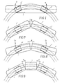
Bei einem Schienenfahrzeug der herkömmlichen Bauart mit zwei Drehgestellen (Fig. 6) 4', 4" und einem Wagenkasten 1' stellt sich bei Bogenfahrt zwischen Wagenkasten 1' und jedem Drehgestell 4' ein Winkel a ein. Diese Darstellung ist idealisiert, insoferne als keine Rücksicht auf Spurspiel und Stellung der Drehgestelle im Spurkanal genommen wurde.In the case of a rail vehicle of the conventional type with two bogies (FIG. 6) 4 ', 4 "and a car body 1', an angle a is established between the car body 1 'and each bogie 4' when traveling in an arc. This representation is idealized, insofar as none Consideration of track play and position of the bogies in the track channel was taken.
Bei etwa mittiger Anordnung der Drehgestelle 4' bzw. 4" (Fig. 7) an zwei gelenkig verbundenen Wagenkasten 1', 1" tritt im Bogen kein Relativwinkel zwischen Wagenkasten 1', 1" und Drehgestell 4" auf. Der gesamte Knickwinkel 2 a stellt sich zwischen den Wagenkästen 1', 1" ein. Der Vergleich der verschiedenen Konzepte ist hier mit immer gleichen Drehgestellabständen vorgenommen.When the
Würde man nun Anschläge am Wagenkastengelenk zur Begrenzung des Knickwinkels anbringen (z.B. max. Knickwinkel a), dann muß der Rest von jeweils a/2 an jedem Drehgestell 4', 4" aufgenommen werden (Fig. 8). Bei dem Fahrzeug gemäß Fig. 9 erfolgt an jedem Wagenkastengelenk eine Knickung um den Winkel a. Dies gilt jedoch nur bei der quasistatischen Bogenfahrt. Dieses Kurvenverhalten wäre mit einem echten Zweiachser vergleichbar. Der geringe Achsstand von ca. 1,8 bis 2,0 m (zwischen 2 aufeinander folgenden Radkästen) bedingt aber hohe Führungskräfte an den anlaufenden Radsätzen, vor allem dann, wenn es zum Befahren einer Krümmungsänderung mit Unstetigkeitsstelle (Übergang Gerade in Bogen) kommt. Es müssen hiebei die Trägheitsmomente des Wagenkastens abgefangen werden.If one were to make stops on the car body joint to limit the articulation angle (eg max. Articulation angle a), then the rest of a / 2 would have to be included on each
Es gibt zwei Möglichkeiten, das Auftreten hoher Führungskräfte zu unterbinden, nämlich entweder Vergrößerung des Radstandes über 3 m gemäß einem in der WO 91/02674 beschriebenen Konzept mit Einzelrad/Einzelfahrwerken, was aber zur Vermeidung großer Anlaufwinkel eine zwangsgesteuerte Radialsteuerung der Einzelfahrwerke bedingt, oder ein Konzept mit "echten" Drehgestellen mit zueinander parallel gehaltenen Radachsen, die eine Ausdrehbewegung des Drehgestelles unter dem Wagenkasten zulassen, wie dies die gegenständliche Erfindung vorschlägt.There are two ways to prevent the appearance of high executives, namely either increasing the wheelbase by more than 3 m in accordance with a concept described in WO 91/02674 with single wheel / single trolleys, which, however, necessitates positively controlled radial control of the individual trolleys to avoid large starting angles, or one Concept with "real" bogies with wheel axles held parallel to each other, which allow the bogie to be turned out under the body, as proposed by the present invention.
Bei Schienenfahrzeugen ist unterschiedlich zu Straßenfahrzeugen eine ausreichende Querfederung notwendig. Da es sich hier vorrangig um ein Nahverkehrsfahrzeug der niederen Geschwindigkeitsklasse handelt, kann die Längsänlenkung des Wagenkastens 1 am Drehgestell 4 starr bzw. sehr steif sein, um Brems- oder Antriebskräfte vom Drehgestell 4 auf den Wagenkasten 1 zu übertragen. Fährt nun ein derartig konzipiertes Fahrzeug (Fig. 9) von der Geraden in den Bogen, dann wird das Drehgestell 4 sofort in den Bogen eingelenkt. Die Masse und auch das Massenträgheitsmoment des Drehgestelles 4 sind klein gegenüber dem des Wagenkastens 1. Der schwerere Wagenkasten 1 verweilt daher zunächst in seiner Lage. Im weiteren Zeitablauf wird durch die elastischen Rückstellkräfte der Sekundärfederung der Wagenkasten 1 der Drehgestellage "nachgezogen". Der Winkel zwischen Drehgestell 4 und Wagenkasten 1 wird hiedurch wieder verringert, bis bei der reinen Kreisbogenfahrt der Winkel den Wert Null erreicht. Die Frequenz und die Amplitude dieses Einschwingvorganges ist von der Charakterstik der Sekundärfeder und deren Dämpfung abhängig.Sufficient transverse suspension is required for rail vehicles, unlike road vehicles. Since this is primarily a commuter vehicle of the lower speed class, the longitudinal linkage of the
Bei Weiterfahrt in den Bogen nimmt der Winkel zwischen Drehgestell 4 und Wagenkasten 1 - wie schon erwähnt - wieder ab. Der Winkel zwischen benachbarten Wagenkasten vergrößert sich und erreicht im konstanten Kreisbogen sein Maximum. Dies unterscheidet das Konzept von jenem der Fig. 6 und 7.When driving further into the curve, the angle between the
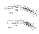
Anhand der Fig. 10 und 11 wird nochmals der Vergleich zwischen dem Gelenksteuerprinzip ohne Brücke etwa gemäß der DE-OS 32 05 613A und dem System gemäß der gegenständlichen Erfindung gezeigt.10 and 11, the comparison between the joint control principle without a bridge, for example according to DE-OS 32 05 613A, and the system according to the present invention is shown.
Das quasistatische Befahren der Bogeneinfahrt bewirkt dort einen Ausdrehwinkel a zwischen den Wagenkästen und den Drehgestellen. Dies tritt bei der Konfiguration mit Brücke 3 (Fig. 11) nicht auf, da die "schwebende" Brücke 3 für einen Ausgleich sorgt.The quasi-static driving through the arc entrance causes an angle of rotation a between the car bodies and the bogies. This does not occur in the configuration with bridge 3 (FIG. 11), since the "floating"
Aus Fig. 16 ist ersichtlich, daß sich das erfindungsgemäße Schienenfahrzeug einem Bogen ideal anpaßt. Der Hüllraum ist mit 33 bezeichnet.16 that the rail vehicle according to the invention adapts ideally to a curve. The envelope is designated 33.
Aus Fig. 17 ist ersichtlich, daß auch in extremen Stellungen, wenn beispielsweise die Brücke 3 sich in der Einfahrt in einen Bogen befindet (Weiche), günstige Verhältnisse hinsichtlich des Bedarfes an Hüllraum 33 erzielt werden und relativ breite Wagenkasten solcherart ausgeführt werden können.From Fig. 17 it can be seen that even in extreme positions, for example when the
Fig. 18 veranschaulicht die Kraftverhältnisse im sogenannten quasistatischen Bodenlauf. Die auf die Brücke 3 wirkende Fliehkraft im Ausmaß von 2B wird je zur Hälfte, somit im Ausmaß B, jeweils auf benachbarten Wagenkasten 1 übertragen. Auf den Wagenkasten wirkt dabei im Abstand x von der Drehgestellmitte eine Kraft A. Wird nun die beziehung A. x = B . y eingehalten, so entstehen keine zusätzlichen Führungskräfte an den Radsätzen. y ist dabei die Entfernung, in der die Kraft B vom Mittelpunkt des Drehgestelles angreift.18 illustrates the force relationships in the so-called quasi-static ground run. The centrifugal force acting on the
Unter der Annahme, daß die Massenverteilung der Wagenkasten, einschließlich der Elektroausrüstung und der Innenausstattung, näherungsweise als Gleichlast angenommen wird, soll der Überhang ü an den endständigen Fahrzeugkasten 1 derAssuming that the mass distribution of the body, including the electrical equipment and the interior, is approximately assumed to be the same load, the overhang ü to the
beziehung![]()
![]()
Dynamische Effekte, die ein Ausdrehen der Drehgestelle 4 um einen Winkel β bewirken, treten bei beiden Konzepten (mit Brücke und ohne Brücke) in etwa gleicher. Größenordnung auf. Der Summenwinkel beim Konzept gemäß Fig. 10 ist größer als bei jenem gemäß Fig. 11. Das bedeutet aber, daß die Durchgangsbreite über den Drehgestellen (Niederflurfahrzeug) bei einer Anordnung gemäß Fig. 10 kleiner sein muß. Ein Vergleich eines quergefederten Zweiachsers (Fig. 13) mit einem drehelastischen Drehgestell gemäß mit Fig. 12 gleicher Querfedersteifigkeit und gleichem Achsstand zeigt, daß der Anlaufwinkel a zwischen Fahrkante der Schiene und der Radebene beim Zweiachser gemäß Fig. 13 höher liegt als beim Drehgestellfahrzeug gemäß Fig. 12.Dynamic effects which cause the
An die Anbindung des Wagenkastens an das Drehgestell werden Anforderungen gestellt, die im Prinzip aus Fig. 15 zu ersehen sind. Fig. 14 zeigt eine weitere Ausführung ebenfalls dem Prinzip nach. Die Anbindung ist quer- und drehelastisch durch die Flexicoilwirkung der Sekundärfederung, welche den Wagenkasten am Drehgestellrahmen abstützt. In den Fig. 14 und 15 deutet der Doppelpfeil D die Drehelastizität und der Doppelpfeil Q die Querelastizität an. Unterstützt kann dies durch zusätzliche Querfederelemente werden, wie dies die Fig. 21, 22 zeigen. Anschläge werden vorgesehen, um den Ausdrehwinkel oder die Querbewegungen zu begrenzen.Requirements are placed on the connection of the car body to the bogie, which can be seen in principle from FIG. 15. 14 shows a further embodiment based on the principle. The connection is transverse and torsionally flexible due to the flexicoil effect of the secondary suspension, which supports the car body on the bogie frame. 14 and 15, the double arrow D indicates the torsional elasticity and the double arrow Q the transverse elasticity. This can be supported by additional transverse spring elements, as shown in FIGS. 21, 22. Stops are provided to limit the angle of rotation or transverse movements.
Zur Übertragung der Brems- und Antriebskräfte ist die Anbindung des Wagenkastens am Drehgestell längssteif oder längsstarr auszuführen, wie nachstehend erläutert wird.To transfer the braking and driving forces, the connection of the car body to the bogie must be longitudinally rigid or longitudinally rigid, as will be explained below.
Die Koppeleinrichtung zwischen den Wagenkasten 1 bzw. 2 und der Querbrücke 6 des Drehgestellrahmens weist gemäß den Fig. 23 und 24 Federpakete 10 und 11 auf, deren Achsen sich im wesentlichen in Fahrzeuglängsrichtung erstrecken und die jeweils mit einem Ende gegen den Wagenkasten 1 bzw. 2 und mit dem anderen Ende an der Querbrücke 6 abgestützt sind. In den Fig. 23 und 24 ist vom Wagenkasten 1 lediglich der Längsträger 15 dargestellt. Die Koppelung zwischen Drehgestell 4 und Wagenkasten 1 ist längsstarr für die Aufnahme von Brems- und Beschleunigungskräften, jedoch - wie später erläutert wird - auch quer- und drehelastisch.23 and 24, the coupling device between the
Die Fig. 19 bis 21 zeigen Anordnungen, in welchen die Koppeleinrichtung als Lenkerverbindung zur Erzielung einer längsstarren Verbindung des Drehgestellrahmens mit dem Wagenkasten ausgebildet ist.19 to 21 show arrangements in which the coupling device is designed as a link connection to achieve a longitudinally rigid connection of the bogie frame to the car body.
In der Ausführung gemäß den Fig. 19 und 20 ist die Koppeleinrichtung 8 als Gelenksparallelogramm ausgebildet. Die Lager 12 der die Kurbeln bildenden Lenker 25 des Gelenksviereckes sind an der Querbrücke 6 im wesentlichen symmetrisch zur Längsmittenebene angeordnet. Die einen zweiarmigen Hebel 13 bildende Koppel des Gelenksparallelogramms durchsetzt einen Querschlitz 14 im Längsträger 15 und damit auch im Wagenkasten 1, 2. Der zweiarmige Hebel 13 ist über eine vertikale Achse 16, die mittig zwischen den im zweiarmigen Hebel 13 befindlichen Lagern 17 der Lenker 25 angeordnet ist, mit dem Längsträger U des Wagenkastens 1 bzw. 2 verbunden.In the embodiment according to FIGS. 19 and 20, the
An der Querbrücke 6 sind symmetrisch zur Längsmittenebene des Drehgestells 4 als Puffer 18 ausgebildete Anschläge (Fig. 19,23,25,26) angeordnet. Der Wagenkasten 1 bzw. 2 besitzt Gegenanschläge 19, die zur Begrenzung der Relativschwenkung zwischen dem Drehgestell 4 und dem Wagenkasten 1 bzw. 2 mit den an der Querbrücke 6 angeordneten Anschlägen, insbes. den Puffern 18, zusammenwirken. Fig. 26 läßt dabei deutlich erkennen, daß im ausgelenkten Zustand der Wagenkasten 1 über einen der Gegenanschläge 19 an einem Puffer 18 anliegt. Die Puffer 18 begrenzen sowohl die Querbewegung des Wagenkastens 1 bzw. 2 gegenüber dem Drehgestell 4 als auch die Ausdrehung des Drehgestelles 4 gegenüber dem Wagenkasten 1 bzw. 2. Die Abfederung des Wagenkastens 1 bzw. 2 gegen das Drehgestell 4 erfolgt über Primär- und Sekundärfedern. Die Primärfederung ist dabei als Gummifeder 26 ausgebildet. Die Sekundärfederung kann aus Stahl oder Gummi oder als Luftfederausgeführtsein. Sie ist mit 27 bezeichnet.On the
Parallel zu jeder Federsäule der Sekundärfeder 27 ist ein Vertikaldämpfer 28 angeordnet.A
Zwischen dem Drehgestell 4 und dem Wagenkasten 1 ist mindestens ein Querdämpfer 29 angeordnet, der auch als Schlingerdämpfer wirksam ist. Jedes Drehgestell ist weiters mit zwei Magnetschienenbremsen 30 versehen. Die Querbrücke 6 ist torsionsweich (X- bzw. H-förmig) ausgeführt, um Verwindungen, die bei Rampenfahrt (Überhöhung in Vignolgleisen) oder bei Gleislagefehlern auftreten, auszugleichen, sodaß keine wesentlich unterschiedlichen Radlasten zustandekommen. Die Radnabenmotoren 23 sind durch Spurhaltestangen 31 verbunden, die gleichzeitig als Bahnräumer dienen können und die genaue Einhaltung des Spurmaßes in allen Betriebszuständen sicherstellen können, um solcherart die diesbezügliche Funktion einer Radsatzwelle, die bei den dargestellten Drehgestellen ja nicht vorhanden ist, zu erfüllen.Between the
In der Ausführung gemäß Fig. 21 ist der zweiarmige Hebel 13 mittig in der in dieser Ausführung H-förmigen Querbrücke 6 gelagert. Die in den Lagern 17 an den beiden Enden des zweiarmigen Hebels 13 gelagerten Lenker 25 sind an ihrem vom Lager 17 abliegenden Ende jeweils am Wagenkasten gelagert. Die Lenker 25 erstrecken sich nach einander entgegengesetzten Richtungen vom zweiarmigen Hebel 13 weg. Zur Unterstützung der Flexicoilwirkung der Sekundärfedern sind zusätzliche Federn 40 vorgesehen, die im wesentlichen quer zur Längsrichtung des Fahrzeuges angeordnet sind.In the embodiment according to FIG. 21, the two-
Eine Ausführungsform einer solchen Feder ist aus Fig. 22 ersichtlich. Die Federteller sind mit 41,42 bezeichnet. Die Zusammendrückung der Feder und damit auch die Quer- bzw. Drehbewegung des Wagenkastens 1 gegenüber dem Drehgestell 4 wird durch einen Anschlag 43 begrenzt, der mit einem Gummipuffer 44 zusammenwirkt. Der Gummipuffer 44 ragt vom Deckel 47 in das Innere eines Gehäuses 48, dessen Boden von einem der Federteller 41 gebildet ist. Der Federteller 41 führt einen, die Feder durchsetzenden Kolben 49, an dem der Anschlag 43, bevorzugt mittels Schrauben 50 befestigt ist. Der Kolben 49 besitzt an seinem freien, vom Anschlag 43 abliegenden Ende eine Lagerbohrung 45 zum anschluß an den Wagenkasten bzw. die Querbrücke, wogegen der Anschluß der Feder 40 an die Querbrücke bzw. den Wagenkasten mittels eines (nicht dargestellten) Zapfens erfolgt, der eine Lagerbohrung 46 in einer mit dem Deckel 47 des Gehäuses 48 verbundenen Lasche 51 durchsetzt.An embodiment of such a spring can be seen in FIG. 22. The spring plates are labeled 41.42. The compression of the spring and thus also the transverse or rotational movement of the
Der zweiarmige Hebel 13 kann, muß jedoch nicht über Federpakete 47 (Gummi/Metallfedern) an der Querbrücke 6 abgestützt sein. Diese Federpakete ergeben eine zusätzliche Drehfederung, welche die Flexicoil-Wirkung der Sekundärfederung 27 bei reiner Drehbewegung des Drehgestelles gegenüber dem Wagenkasten unterstützt. Die Anordnung der Federpakete 47 ist dabei so getroffen, daß bei Drehung - je nach Drehrichtung - jeweils nur ein Federpaket auf Druck beansprucht wird.The two-
Mit 32 sind in der Zeichnung die Bremsscheiben bezeichnet, die bei Normalspur (Fig. 19, 20 sowie 23 - 26, 28) innerhalb der Spurweite liegen, bei Schmalspur (Fig. 29) jedoch außerhalb der Spurweite angeordnet sind.With 32 in the drawing, the brake disks are designated, which are within the track gauge in normal gauge (Fig. 19, 20 and 23 - 26, 28), but are arranged outside the track gauge in narrow gauge (Fig. 29).
Claims (7)
ü = a1+2b/a
beträgt, wobei a der Abstand des dem Drehgestell (4) benachbarten Gelenkes (9) von der Mitte des Drehgestells (4) und b der Abstand des Gelenkes (9) von der Mitte der mit dem endständigen Wagenkasten (1) gekuppelten Brücke (3) ist.7. Rail vehicle according to one of claims 1 to 6, characterized in that the distance ü the center of the bogie (4) (real or ideal vertical pivot axis of the bogie with respect to the car body) from the free end of the terminal car body (1)
ü = a1 + 2b / a
, where a is the distance of the joint (9) adjacent to the bogie (4) from the center of the bogie (4) and b is the distance of the joint (9) from the center of the bridge (3) coupled to the terminal car body (1) is.
Applications Claiming Priority (2)
| Application Number | Priority Date | Filing Date | Title |
|---|---|---|---|
| AT2514/91 | 1991-12-19 | ||
| AT0251491A AT403267B (en) | 1991-12-19 | 1991-12-19 | RAIL VEHICLE, IN PARTICULAR LOW-FLOOR VEHICLE |
Publications (2)
| Publication Number | Publication Date |
|---|---|
| EP0548044A1 true EP0548044A1 (en) | 1993-06-23 |
| EP0548044B1 EP0548044B1 (en) | 1998-05-20 |
Family
ID=3535647
Family Applications (1)
| Application Number | Title | Priority Date | Filing Date |
|---|---|---|---|
| EP92890267A Expired - Lifetime EP0548044B1 (en) | 1991-12-19 | 1992-12-18 | Rail vehicle |
Country Status (4)
| Country | Link |
|---|---|
| EP (1) | EP0548044B1 (en) |
| AT (2) | AT403267B (en) |
| DE (1) | DE59209335D1 (en) |
| ES (1) | ES2118806T3 (en) |
Cited By (16)
| Publication number | Priority date | Publication date | Assignee | Title |
|---|---|---|---|---|
| WO1998024674A1 (en) * | 1996-12-07 | 1998-06-11 | Gutehoffnungshütte Radsatz Gmbh | Driven idler wheel axle |
| EP1065123A3 (en) * | 1999-06-29 | 2001-05-23 | Mitsubishi Heavy Industries, Ltd. | Independent wheel driving component, independent wheel steering bogie and cooling structure |
| WO2001064493A1 (en) * | 2000-03-03 | 2001-09-07 | Daimlerchrysler Ag | Railed vehicle with bodies and at least one chassis |
| EP2366599A1 (en) * | 2010-03-18 | 2011-09-21 | Vossloh España S.A. | Rail vehicle, in particular a low-floor rail vehicle |
| DE102013204483A1 (en) | 2013-03-14 | 2014-09-18 | Bombardier Transportation Gmbh | Modular rail vehicle with modules of different widths |
| AT518820A1 (en) * | 2016-06-30 | 2018-01-15 | Siemens Ag Oesterreich | Elastic carrier system for a rail vehicle |
| EP2543570B1 (en) | 2011-07-07 | 2018-03-28 | Bombardier Transportation GmbH | Construction method for the layoutof a railway vehicle car, method for producing a railway vehicle car and rail vehicle car series |
| CN107901993A (en) * | 2017-12-18 | 2018-04-13 | 成都市新筑路桥机械股份有限公司 | A kind of articulated coach of floated compartment automatic tracking |
| CN110308724A (en) * | 2019-07-01 | 2019-10-08 | 百度在线网络技术(北京)有限公司 | Automatic Pilot control method, device, vehicle, storage medium and electronic equipment |
| WO2020192860A1 (en) | 2019-03-22 | 2020-10-01 | Stadler Rail Ag | Bogie for a rail vehicle and rail vehicle carriage having at least one bogie, rail vehicle having at least one rail vehicle carriage, and method for adjusting the height of a carriage body of a rail vehicle carriage |
| EP3798076A1 (en) | 2019-09-27 | 2021-03-31 | Traktionssysteme Austria GmbH | Gearbox |
| EP3799271A1 (en) | 2019-09-27 | 2021-03-31 | Traktionssysteme Austria GmbH | Electric machine |
| CN112644549A (en) * | 2019-10-10 | 2021-04-13 | 中车唐山机车车辆有限公司 | Bogie and rail vehicle |
| EP3854655A1 (en) * | 2020-01-23 | 2021-07-28 | ALSTOM Transport Technologies | Bogie for vehicle with independent wheels and associated vehicle |
| EP3315799B2 (en) † | 2016-10-26 | 2022-02-23 | GESIPA Blindniettechnik GmbH | Blind rivet nut |
| CN114537461A (en) * | 2022-02-14 | 2022-05-27 | 中铁工程装备集团隧道设备制造有限公司 | Bogie for large-tonnage tunnel tractor and large-tonnage tunnel tractor |
Families Citing this family (4)
| Publication number | Priority date | Publication date | Assignee | Title |
|---|---|---|---|---|
| US4077563A (en) * | 1971-02-17 | 1978-03-07 | Karl Bo Lennart Lovqvist | Collecting device for refuse, dust etcetera |
| DE102015211577A1 (en) | 2015-06-23 | 2016-12-29 | Bombardier Transportation Gmbh | Arrangement and method for optimizing the envelope of rail vehicles in sectional construction |
| FR3042769B1 (en) | 2015-10-23 | 2019-06-21 | Alstom Transport Technologies | RAILWAY VEHICLE COMPRISING AT LEAST ONE LOWER BOGIE |
| EP3955435A1 (en) | 2020-08-10 | 2022-02-16 | Traktionssysteme Austria GmbH | Electric traction machine with no housing |
Citations (5)
| Publication number | Priority date | Publication date | Assignee | Title |
|---|---|---|---|---|
| CH153359A (en) * | 1931-01-22 | 1932-03-15 | Christoph & Unmack Aktiengesel | Articulated trolley. |
| DE1455185A1 (en) * | 1962-11-13 | 1969-12-18 | Schweizerische Waggon Und Aufz | Multi-part articulated rail vehicle |
| DE2604769A1 (en) * | 1976-02-07 | 1977-08-11 | Maschf Augsburg Nuernberg Ag | DEVICE FOR GUIDING A RAIL VEHICLE BURST ON THE BASE OF THE CAR BODY |
| FR2442167A1 (en) * | 1978-11-24 | 1980-06-20 | Maschf Augsburg Nuernberg Ag | BOGGIE WITHOUT DANCE TRAVERSE, WITH PNEUMATIC SUSPENSION FOR RAIL VEHICLES |
| EP0271451A2 (en) * | 1986-11-05 | 1988-06-15 | FIAT FERROVIARIA SAVIGLIANO S.p.A. | Bogie for railway vehicle |
Family Cites Families (6)
| Publication number | Priority date | Publication date | Assignee | Title |
|---|---|---|---|---|
| US660226A (en) * | 1899-12-02 | 1900-10-23 | Lewis Miller Smyth | Gate-latch. |
| DE672163C (en) * | 1934-03-09 | 1939-02-22 | Curt Stedefeld Dipl Ing | Suspension for rail vehicles, the car body of which is transversely movable with respect to the drive |
| DE708811C (en) * | 1936-08-18 | 1941-07-30 | Clemens A Voigt | Elastic mounting of the car body on the bogie of vehicles, in particular rail vehicles |
| FR1486355A (en) * | 1966-07-11 | 1967-06-23 | Ganz Mavag Mozdony Vagon | Suspension of the body for bogie railway vehicles |
| DE3205613C2 (en) * | 1982-02-17 | 1985-09-05 | M.A.N. Maschinenfabrik Augsburg-Nürnberg AG, 8500 Nürnberg | Articulated control of four-axle rail vehicles, especially light rail vehicles |
| GR1000703B (en) * | 1989-08-21 | 1992-10-08 | Schindler Waggon | Body of a tramcar |
-
1991
- 1991-12-19 AT AT0251491A patent/AT403267B/en not_active IP Right Cessation
-
1992
- 1992-12-18 AT AT92890267T patent/ATE166298T1/en active
- 1992-12-18 ES ES92890267T patent/ES2118806T3/en not_active Expired - Lifetime
- 1992-12-18 EP EP92890267A patent/EP0548044B1/en not_active Expired - Lifetime
- 1992-12-18 DE DE59209335T patent/DE59209335D1/en not_active Expired - Lifetime
Patent Citations (5)
| Publication number | Priority date | Publication date | Assignee | Title |
|---|---|---|---|---|
| CH153359A (en) * | 1931-01-22 | 1932-03-15 | Christoph & Unmack Aktiengesel | Articulated trolley. |
| DE1455185A1 (en) * | 1962-11-13 | 1969-12-18 | Schweizerische Waggon Und Aufz | Multi-part articulated rail vehicle |
| DE2604769A1 (en) * | 1976-02-07 | 1977-08-11 | Maschf Augsburg Nuernberg Ag | DEVICE FOR GUIDING A RAIL VEHICLE BURST ON THE BASE OF THE CAR BODY |
| FR2442167A1 (en) * | 1978-11-24 | 1980-06-20 | Maschf Augsburg Nuernberg Ag | BOGGIE WITHOUT DANCE TRAVERSE, WITH PNEUMATIC SUSPENSION FOR RAIL VEHICLES |
| EP0271451A2 (en) * | 1986-11-05 | 1988-06-15 | FIAT FERROVIARIA SAVIGLIANO S.p.A. | Bogie for railway vehicle |
Cited By (25)
| Publication number | Priority date | Publication date | Assignee | Title |
|---|---|---|---|---|
| WO1998024674A1 (en) * | 1996-12-07 | 1998-06-11 | Gutehoffnungshütte Radsatz Gmbh | Driven idler wheel axle |
| EP1065123A3 (en) * | 1999-06-29 | 2001-05-23 | Mitsubishi Heavy Industries, Ltd. | Independent wheel driving component, independent wheel steering bogie and cooling structure |
| WO2001064493A1 (en) * | 2000-03-03 | 2001-09-07 | Daimlerchrysler Ag | Railed vehicle with bodies and at least one chassis |
| US6923125B2 (en) | 2000-03-03 | 2005-08-02 | Bombardier Transportation Gmbh | Railed vehicle with bodies and at least one chassis |
| EP2366599A1 (en) * | 2010-03-18 | 2011-09-21 | Vossloh España S.A. | Rail vehicle, in particular a low-floor rail vehicle |
| EP2543570B1 (en) | 2011-07-07 | 2018-03-28 | Bombardier Transportation GmbH | Construction method for the layoutof a railway vehicle car, method for producing a railway vehicle car and rail vehicle car series |
| DE102013204483A1 (en) | 2013-03-14 | 2014-09-18 | Bombardier Transportation Gmbh | Modular rail vehicle with modules of different widths |
| AT518820B1 (en) * | 2016-06-30 | 2018-07-15 | Siemens Ag Oesterreich | Elastic carrier system for a rail vehicle |
| AT518820A1 (en) * | 2016-06-30 | 2018-01-15 | Siemens Ag Oesterreich | Elastic carrier system for a rail vehicle |
| EP3315799B2 (en) † | 2016-10-26 | 2022-02-23 | GESIPA Blindniettechnik GmbH | Blind rivet nut |
| CN107901993A (en) * | 2017-12-18 | 2018-04-13 | 成都市新筑路桥机械股份有限公司 | A kind of articulated coach of floated compartment automatic tracking |
| WO2020192860A1 (en) | 2019-03-22 | 2020-10-01 | Stadler Rail Ag | Bogie for a rail vehicle and rail vehicle carriage having at least one bogie, rail vehicle having at least one rail vehicle carriage, and method for adjusting the height of a carriage body of a rail vehicle carriage |
| CN110308724A (en) * | 2019-07-01 | 2019-10-08 | 百度在线网络技术(北京)有限公司 | Automatic Pilot control method, device, vehicle, storage medium and electronic equipment |
| US11524702B2 (en) | 2019-07-01 | 2022-12-13 | Apollo Intelligent Driving Technology (Beijing) Co., Ltd. | Method and device for autonomous driving control, vehicle, storage medium and electronic device |
| CN110308724B (en) * | 2019-07-01 | 2022-06-03 | 阿波罗智能技术(北京)有限公司 | Automatic driving control method, automatic driving control device, vehicle, storage medium and electronic equipment |
| EP3798076A1 (en) | 2019-09-27 | 2021-03-31 | Traktionssysteme Austria GmbH | Gearbox |
| EP3799271A1 (en) | 2019-09-27 | 2021-03-31 | Traktionssysteme Austria GmbH | Electric machine |
| WO2021058151A1 (en) * | 2019-09-27 | 2021-04-01 | Traktionssysteme Austria Gmbh | Traction transmission |
| US11679788B2 (en) | 2019-09-27 | 2023-06-20 | Traktionssysteme Austria Gmbh | Traction transmission |
| CN112644549B (en) * | 2019-10-10 | 2022-06-14 | 中车唐山机车车辆有限公司 | Bogie and rail vehicle |
| CN112644549A (en) * | 2019-10-10 | 2021-04-13 | 中车唐山机车车辆有限公司 | Bogie and rail vehicle |
| EP3854655A1 (en) * | 2020-01-23 | 2021-07-28 | ALSTOM Transport Technologies | Bogie for vehicle with independent wheels and associated vehicle |
| FR3106557A1 (en) * | 2020-01-23 | 2021-07-30 | Alstom Transport Technologies | Bogie for independent wheel vehicle and associated vehicle |
| CN114537461A (en) * | 2022-02-14 | 2022-05-27 | 中铁工程装备集团隧道设备制造有限公司 | Bogie for large-tonnage tunnel tractor and large-tonnage tunnel tractor |
| CN114537461B (en) * | 2022-02-14 | 2023-09-01 | 中铁工程装备集团隧道设备制造有限公司 | Bogie for large-tonnage tunnel tractor and large-tonnage tunnel tractor |
Also Published As
| Publication number | Publication date |
|---|---|
| AT403267B (en) | 1997-12-29 |
| ES2118806T3 (en) | 1998-10-01 |
| ATE166298T1 (en) | 1998-06-15 |
| DE59209335D1 (en) | 1998-06-25 |
| ATA251491A (en) | 1997-05-15 |
| EP0548044B1 (en) | 1998-05-20 |
Similar Documents
| Publication | Publication Date | Title |
|---|---|---|
| EP0548044B1 (en) | Rail vehicle | |
| DE3111087C2 (en) | Single wheel arrangement for railway vehicles | |
| EP0567950A1 (en) | Railway vehicle | |
| EP0337135B1 (en) | Guiding means for the running gear of railway vehicles, especially short distance traffic vehicles | |
| EP0649782B1 (en) | Railway vehicle and railway train for such a vehicle | |
| EP3131800A1 (en) | Articulated vehicle with a transversely displaceable joint | |
| EP0580995B1 (en) | Track guided vehicle system consisting of at least two vehicles with stored running gears with single wheelsets | |
| EP0168578A2 (en) | Set of wheels for railway vehicles | |
| EP1674367B1 (en) | Device for the articulated linkage between two bodies of a multi-unit railway vehicle | |
| DE19507021C2 (en) | Chassis for railway vehicles | |
| EP0855326B1 (en) | Two axled running gear for trackbound transport systems | |
| EP0507146A1 (en) | Railway vehicle especially low floor vehicle | |
| EP0838386B1 (en) | Railway vehicle with at least one running gear and running gear for such a vehicle | |
| DE4320667A1 (en) | Low-floor rail vehicle | |
| EP0658465B1 (en) | Self steering three axle bogie for a railway vehicle | |
| EP0439573B1 (en) | Bogie for an underslung vehicle | |
| EP0388999A2 (en) | Mechanical device for supporting railway vehicles | |
| AT398557B (en) | Chassis for a rail vehicle, in particular low-platform vehicle | |
| EP0678436B1 (en) | Self steering three axled bogie for a railway vehicle | |
| EP0930210B1 (en) | Running gear for railway vehicles and railway vehicle with at least one such running gear | |
| EP0410407B1 (en) | Wheel sub-frames for railway vehicles or bogies | |
| DE1936932A1 (en) | Bogie for rail vehicles with individual suspension of the wheel sets | |
| DE4422109C2 (en) | Couplable undercarriage arrangement for supporting and transverse inclination of a car body | |
| EP0941191B1 (en) | Rolling mechanism for rail vehicle | |
| EP3109121B1 (en) | Bogie for multi-section rail vehicles and multi-section rail vehicle |
Legal Events
| Date | Code | Title | Description |
|---|---|---|---|
| PUAI | Public reference made under article 153(3) epc to a published international application that has entered the european phase |
Free format text: ORIGINAL CODE: 0009012 |
|
| AK | Designated contracting states |
Kind code of ref document: A1 Designated state(s): AT BE CH DE ES FR GB GR IT LI NL PT SE |
|
| 17P | Request for examination filed |
Effective date: 19931217 |
|
| 17Q | First examination report despatched |
Effective date: 19941209 |
|
| GRAG | Despatch of communication of intention to grant |
Free format text: ORIGINAL CODE: EPIDOS AGRA |
|
| GRAG | Despatch of communication of intention to grant |
Free format text: ORIGINAL CODE: EPIDOS AGRA |
|
| GRAH | Despatch of communication of intention to grant a patent |
Free format text: ORIGINAL CODE: EPIDOS IGRA |
|
| GRAH | Despatch of communication of intention to grant a patent |
Free format text: ORIGINAL CODE: EPIDOS IGRA |
|
| GRAA | (expected) grant |
Free format text: ORIGINAL CODE: 0009210 |
|
| AK | Designated contracting states |
Kind code of ref document: B1 Designated state(s): AT BE CH DE ES FR GB GR IT LI NL PT SE |
|
| PG25 | Lapsed in a contracting state [announced via postgrant information from national office to epo] |
Ref country code: GR Free format text: LAPSE BECAUSE OF NON-PAYMENT OF DUE FEES Effective date: 19980520 |
|
| REF | Corresponds to: |
Ref document number: 166298 Country of ref document: AT Date of ref document: 19980615 Kind code of ref document: T |
|
| REG | Reference to a national code |
Ref country code: CH Ref legal event code: EP |
|
| REF | Corresponds to: |
Ref document number: 59209335 Country of ref document: DE Date of ref document: 19980625 |
|
| ITF | It: translation for a ep patent filed |
Owner name: ING. A. GIAMBROCONO & C. S.R.L. |
|
| PG25 | Lapsed in a contracting state [announced via postgrant information from national office to epo] |
Ref country code: PT Free format text: LAPSE BECAUSE OF FAILURE TO SUBMIT A TRANSLATION OF THE DESCRIPTION OR TO PAY THE FEE WITHIN THE PRESCRIBED TIME-LIMIT Effective date: 19980820 |
|
| GBT | Gb: translation of ep patent filed (gb section 77(6)(a)/1977) |
Effective date: 19980814 |
|
| REG | Reference to a national code |
Ref country code: CH Ref legal event code: NV Representative=s name: LUCHS & PARTNER PATENTANWAELTE |
|
| REG | Reference to a national code |
Ref country code: ES Ref legal event code: FG2A Ref document number: 2118806 Country of ref document: ES Kind code of ref document: T3 |
|
| ET | Fr: translation filed | ||
| PLBE | No opposition filed within time limit |
Free format text: ORIGINAL CODE: 0009261 |
|
| STAA | Information on the status of an ep patent application or granted ep patent |
Free format text: STATUS: NO OPPOSITION FILED WITHIN TIME LIMIT |
|
| 26N | No opposition filed | ||
| REG | Reference to a national code |
Ref country code: GB Ref legal event code: IF02 |
|
| REG | Reference to a national code |
Ref country code: FR Ref legal event code: TP |
|
| PGFP | Annual fee paid to national office [announced via postgrant information from national office to epo] |
Ref country code: AT Payment date: 20101214 Year of fee payment: 19 |
|
| PGFP | Annual fee paid to national office [announced via postgrant information from national office to epo] |
Ref country code: GB Payment date: 20101221 Year of fee payment: 19 |
|
| PGFP | Annual fee paid to national office [announced via postgrant information from national office to epo] |
Ref country code: SE Payment date: 20111223 Year of fee payment: 20 Ref country code: CH Payment date: 20111227 Year of fee payment: 20 Ref country code: NL Payment date: 20111228 Year of fee payment: 20 Ref country code: FR Payment date: 20120105 Year of fee payment: 20 Ref country code: ES Payment date: 20111227 Year of fee payment: 20 |
|
| PGFP | Annual fee paid to national office [announced via postgrant information from national office to epo] |
Ref country code: BE Payment date: 20111229 Year of fee payment: 20 |
|
| PGFP | Annual fee paid to national office [announced via postgrant information from national office to epo] |
Ref country code: DE Payment date: 20111222 Year of fee payment: 20 |
|
| PGFP | Annual fee paid to national office [announced via postgrant information from national office to epo] |
Ref country code: IT Payment date: 20111229 Year of fee payment: 20 |
|
| REG | Reference to a national code |
Ref country code: DE Ref legal event code: R071 Ref document number: 59209335 Country of ref document: DE |
|
| REG | Reference to a national code |
Ref country code: DE Ref legal event code: R071 Ref document number: 59209335 Country of ref document: DE |
|
| REG | Reference to a national code |
Ref country code: NL Ref legal event code: V4 Effective date: 20121218 |
|
| BE20 | Be: patent expired |
Owner name: *BOMBARDIER-WIEN SCHIENENFAHRZEUGE A.G. Effective date: 20121218 |
|
| REG | Reference to a national code |
Ref country code: CH Ref legal event code: PL |
|
| REG | Reference to a national code |
Ref country code: GB Ref legal event code: PE20 Expiry date: 20121217 |
|
| REG | Reference to a national code |
Ref country code: SE Ref legal event code: EUG |
|
| PG25 | Lapsed in a contracting state [announced via postgrant information from national office to epo] |
Ref country code: GB Free format text: LAPSE BECAUSE OF EXPIRATION OF PROTECTION Effective date: 20121217 |
|
| REG | Reference to a national code |
Ref country code: AT Ref legal event code: MK07 Ref document number: 166298 Country of ref document: AT Kind code of ref document: T Effective date: 20121218 |
|
| REG | Reference to a national code |
Ref country code: ES Ref legal event code: FD2A Effective date: 20140827 |
|
| PG25 | Lapsed in a contracting state [announced via postgrant information from national office to epo] |
Ref country code: ES Free format text: LAPSE BECAUSE OF EXPIRATION OF PROTECTION Effective date: 20121219 |