EP0548044A1 - Véhicule ferroviaire - Google Patents
Véhicule ferroviaire Download PDFInfo
- Publication number
- EP0548044A1 EP0548044A1 EP92890267A EP92890267A EP0548044A1 EP 0548044 A1 EP0548044 A1 EP 0548044A1 EP 92890267 A EP92890267 A EP 92890267A EP 92890267 A EP92890267 A EP 92890267A EP 0548044 A1 EP0548044 A1 EP 0548044A1
- Authority
- EP
- European Patent Office
- Prior art keywords
- bogie
- car body
- supported
- bridge
- rail vehicle
- Prior art date
- Legal status (The legal status is an assumption and is not a legal conclusion. Google has not performed a legal analysis and makes no representation as to the accuracy of the status listed.)
- Granted
Links
Images


Classifications
-
- B—PERFORMING OPERATIONS; TRANSPORTING
- B61—RAILWAYS
- B61D—BODY DETAILS OR KINDS OF RAILWAY VEHICLES
- B61D13/00—Tramway vehicles
-
- B—PERFORMING OPERATIONS; TRANSPORTING
- B61—RAILWAYS
- B61F—RAIL VEHICLE SUSPENSIONS, e.g. UNDERFRAMES, BOGIES OR ARRANGEMENTS OF WHEEL AXLES; RAIL VEHICLES FOR USE ON TRACKS OF DIFFERENT WIDTH; PREVENTING DERAILING OF RAIL VEHICLES; WHEEL GUARDS, OBSTRUCTION REMOVERS OR THE LIKE FOR RAIL VEHICLES
- B61F5/00—Constructional details of bogies; Connections between bogies and vehicle underframes; Arrangements or devices for adjusting or allowing self-adjustment of wheel axles or bogies when rounding curves
- B61F5/02—Arrangements permitting limited transverse relative movements between vehicle underframe or bolster and bogie; Connections between underframes and bogies
- B61F5/14—Side bearings
- B61F5/148—Side bearings between bolsterless bogies and underframes
Definitions
- the invention relates to a rail vehicle, in particular a low-floor vehicle, e.g. for local transport, such as trams and the like, with a plurality of car bodies which can be pivoted relative to one another, each of which is supported on a, in particular cradle-less, bogie by means of secondary springs, the wheels of which are possibly driven, the wheels of the bogie on the bogie frame, in particular via a swing arm each , are mounted and a coupling device is provided for connecting the bogie frame to the car body and between two car bodies each supported on a bogie, a bridge designed as a floating car bodies is arranged, which is supported by one of two joints spaced apart in the vehicle longitudinal direction with the neighboring, supported Car body is coupled.
- trams and light rail vehicles are preferably of low-floor design, with only one step to be overcome compared to three or more steps in the case of conventional vehicles when boarding and alighting.
- the aim is to avoid platforms on the inside of the car.
- the car body makes the movement of the bogie as it enters a curve, provided that the bogie is rigidly connected to this car body.
- the spontaneous rotation of the car body, which occurs here, is undoubtedly registered by the passengers.
- the rail vehicle according to the invention has high driving comfort due to the damping of the transverse movements of the car body.
- "real" bogies with wheel axles that are always parallel to each other, at a small mutual distance of, for example, 1.8 to 2 m), which allow the bogie to be unscrewed from under the body, the transmission to the body is delayed, so do the managers reduced at the starting wheel sets. This also increases driving comfort and reduces wheel-rail wear.
- the car body having counter stops, which limit the relative pivoting between the bogie and car body with the stops arranged on the cross bridge, in particular the buffers, cooperate, it is ensured that the bogie comes to the side of the car body only after a certain rotation (about 2 °) via the buffer.
- the transverse spring characteristic is therefore non-linear.
- the coupling device for the longitudinally rigid connection has spring assemblies, the axes of which extend essentially in the longitudinal direction of the vehicle and which each have one end on the body and the other end are supported on the bogie frame.
- the springs extending in the longitudinal direction of the vehicle hinder transverse and rotational movements of the car body relative to the bogie with only small restoring forces.
- a further embodiment of the subject matter of the invention provides that the coupling device is designed as a link connection and that this link connection has a two-armed connection Has lever, which is preferably pivotally connected to the center of the car body, in particular with a longitudinal member of the car body or with the cross bridge connecting the two longitudinal members of the bogie frame, wherein in the area of each end of the two-armed lever a handlebar engages, which with its from the two-armed Lever remote end engages on the cross bridge or in the case of the two-armed lever on the cross bridge, is articulated to the body.
- a handlebar engages, which with its from the two-armed Lever remote end engages on the cross bridge or in the case of the two-armed lever on the cross bridge, is articulated to the body.
- the two-armed lever pivotally connected to the longitudinal member of the car body passes through a transverse slot in the car body and is preferably connected to the car body or its longitudinal member via a vertical axis.
- additional springs acting transversely to the longitudinal direction of the vehicle can be provided. These springs can be arranged centrally symmetrically between the cross bridge of the bogie frame and the body.
- the two-armed lever can be supported by spring packs on the bogie frame, in particular on its cross bridge, to support the flexicoil effect of the secondary suspension with a pure rotary movement between the bogie and car body.
- the need for envelope space in curves is favorably influenced if, in a manner known per se, the length of the bridge is at most equal to the length of the adjacent supported car body.
- the aforementioned configuration makes it possible to keep the envelope space small.
- each wheel arch is arranged under two rows of pairs of seats facing one another with their backrests and laterally adjacent to one another. This enables the low-floor floor to be arranged around the wheel arches without platforms.
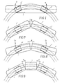
- a train can be assembled modularly, the sum of the number of supported and the number of floating car bodies being an odd number, in particular 3.5 or 7.
- the smallest basic unit is a vehicle consisting of three car bodies, namely two supported and one floating car body, which is arranged between the two supported car bodies.
- the joints between the floating car body and each of the adjacent car bodies are designed as tannin joints, at In longer vehicles, the other joints are alternately designed as a tanner's joint and as a simple joint, so that changes in inclination that occur in the course of the track and their transitional roundings can be easily negotiated.
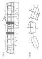
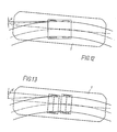
- 1 and 2 car bodies are designated, which are pivotable against each other.
- the car body 1 is one which is arranged at the ends of the rail vehicle, whereas the car body designated by 2 is arranged between the terminal car body 1.
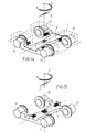
- Each of the swiveling car bodies 1, 2 is supported on a bogie 4 which is cradle-free in the exemplary embodiment shown.
- the wheels 5 of the bogie can be driven, but bogies with non-driven wheels 5 are also possible.
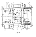
- the wheels 5 of the bogie 4 are mounted on a cross bridge 6 of the bogie frame, in particular in rockers 7 (FIGS. 20, 24).
- the swing arm bearing is designated 22.
- a coupling device designated 8 is provided in the drawing.
- a bridge 3 is arranged, which is designed as a floating car body and in each case via one of two joints 9 spaced apart in the longitudinal direction of the vehicle with the adjacent car bodies 1, 2, each supported on a bogie is coupled.
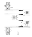
- Fig. 1 the smallest basic unit of a rail vehicle is shown, which consists of a total of three car bodies, namely two terminal car body 1 and a car body 3 located in between.
- the joints 9 are designed in such a basic unit as Gerber joints and form a vertical axis of rotation and moments take up around the lateral axis.
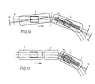
- FIG. 2 illustrates in more detail, the system is modular, so that rail vehicles consisting of five, seven and multi-car bodies are possible, as illustrated in FIGS. 3-5 and 16 and 17.
- the hinge 9 is shown symbolically in the drawings only by the bellows-like outer lining.
- the drive is preferably carried out via wheel hub motors 23, which can be designed as three-phase asynchronous motors, via planetary gears 24 directly onto the wheels 5.
- wheel hub motors 23 can be designed as three-phase asynchronous motors, via planetary gears 24 directly onto the wheels 5.
- This compact arrangement allows the drive to be located directly under adjacent wheel housings 20 (FIG 27-29), the seats with their backrests 21 being arranged dos-a-dos on each box 12 without the need to provide platforms in the passenger compartment. This way it is possible to get one through reaching low floor height of approx.
- FIGS. 28 and 29 show that the seat arrangement is identical to that even with a narrow track up to 900 mm track width Seat arrangement for cars for standard gauge, however the bogie frame for narrow gauge is narrower than for standard gauge.
- the length of the bridge 3 is at most equal to the length of the car bodies 1 and 2, which are adjacent to it in the rail vehicle and supported on the bogies, if the requirement for a small envelope space is required.
- the envelope is designated 33.
- connection of the car body to the bogie which can be seen in principle from FIG. 15.
- 14 shows a further embodiment based on the principle.
- the connection is transverse and torsionally flexible due to the flexicoil effect of the secondary suspension, which supports the car body on the bogie frame.
- the double arrow D indicates the torsional elasticity and the double arrow Q the transverse elasticity. This can be supported by additional transverse spring elements, as shown in FIGS. 21, 22. Stops are provided to limit the angle of rotation or transverse movements.
- connection of the car body to the bogie must be longitudinally rigid or longitudinally rigid, as will be explained below.
- the coupling device between the car bodies 1 and 2 and the cross bridge 6 of the bogie frame has spring assemblies 10 and 11, the axes of which essentially extend in the longitudinal direction of the vehicle and each end with one end against the car bodies 1 and 2 and are supported at the other end on the cross bridge 6. 23 and 24, only the side member 15 of the car body 1 is shown.
- the coupling between the bogie 4 and the body 1 is longitudinally rigid for absorbing braking and acceleration forces, but - as will be explained later - also transverse and torsionally elastic.
- 19 to 21 show arrangements in which the coupling device is designed as a link connection to achieve a longitudinally rigid connection of the bogie frame to the car body.
- the coupling device 8 is designed as an articulated parallelogram.
- the bearings 12 of the handlebars 25 of the quadrangle forming the cranks are arranged on the cross bridge 6 essentially symmetrically to the longitudinal center plane.
- the coupling of the articulated parallelogram, which forms a two-armed lever 13 passes through a transverse slot 14 in the longitudinal member 15 and thus also in the car body 1, 2.
- the two-armed lever 13 is via a vertical axis 16 which is centered between the bearings 17 in the two-armed lever 13 of the handlebars 25 is arranged, connected to the longitudinal beam U of the car body 1 or 2.
- stops 18 designed as buffers are arranged symmetrically to the longitudinal center plane of the bogie 4.
- the car body 1 or 2 has counter stops 19 which cooperate with the stops arranged on the cross bridge 6, in particular the buffers 18, to limit the relative pivoting between the bogie 4 and the car body 1 or 2.
- Fig. 26 clearly shows that in the deflected state the car body 1 abuts one of the counter stops 19 on a buffer 18.
- the buffers 18 limit both the transverse movement of the car body 1 or 2 with respect to the bogie 4 and the turning of the bogie 4 with respect to the car body 1 or 2.
- the suspension of the car body 1 or 2 against the bogie 4 takes place via primary and secondary springs .
- the primary suspension is designed as a rubber spring 26.
- the secondary suspension can be made of steel or rubber or as an air spring. It is designated 27.
- a vertical damper 28 is arranged parallel to each spring column of the secondary spring 27.
- each bogie is also provided with two magnetic rail brakes 30.
- the cross bridge 6 is torsionally soft (X- or H-shaped) in order to compensate for torsion that occurs when driving on a ramp (elevation in Vignol tracks) or with track position errors, so that no significantly different wheel loads occur.
- the wheel hub motors 23 are connected by track holding rods 31, which can simultaneously serve as track clearers and can ensure the exact observance of the track dimension in all operating states art to perform the relevant function of a wheelset shaft, which is not present in the bogies shown.
- the two-armed lever 13 is mounted centrally in the H-shaped cross bridge 6 in this embodiment.
- the handlebars 25 mounted in the bearings 17 at the two ends of the two-armed lever 13 are each mounted on the car body at their end remote from the bearing 17.
- the links 25 extend in opposite directions away from the two-armed lever 13.
- additional springs 40 are provided, which are arranged essentially transversely to the longitudinal direction of the vehicle.
- FIG. 22 An embodiment of such a spring can be seen in FIG. 22.
- the spring plates are labeled 41.42.
- the compression of the spring and thus also the transverse or rotational movement of the body 1 relative to the bogie 4 is limited by a stop 43 which cooperates with a rubber buffer 44.
- the rubber buffer 44 protrudes from the cover 47 into the interior of a housing 48, the bottom of which is formed by one of the spring plates 41.
- the spring plate 41 guides a piston 49 passing through the spring, to which the stop 43 is fastened, preferably by means of screws 50.
- the piston 49 has at its free end remote from the stop 43 a bearing bore 45 for connection to the car body or the cross bridge, whereas the spring 40 is connected to the cross bridge or the car body by means of a pin (not shown), which is a Bearing hole 46 passes through in a tab 51 connected to the cover 47 of the housing 48.
- the two-armed lever 13 can, but does not have to be supported on the cross bridge 6 via spring assemblies 47 (rubber / metal springs). These spring assemblies result in an additional torsion spring, which supports the flexicoil effect of the secondary suspension 27 with a pure rotational movement of the bogie relative to the car body.
- the arrangement of the spring assemblies 47 is such that when rotating - depending on the direction of rotation - only one spring assembly is subjected to pressure.
- the brake disks are designated, which are within the track gauge in normal gauge (Fig. 19, 20 and 23 - 26, 28), but are arranged outside the track gauge in narrow gauge (Fig. 29).
Applications Claiming Priority (2)
| Application Number | Priority Date | Filing Date | Title |
|---|---|---|---|
| AT2514/91 | 1991-12-19 | ||
| AT0251491A AT403267B (de) | 1991-12-19 | 1991-12-19 | Schienenfahrzeug, insbesondere niederflurfahrzeug |
Publications (2)
| Publication Number | Publication Date |
|---|---|
| EP0548044A1 true EP0548044A1 (fr) | 1993-06-23 |
| EP0548044B1 EP0548044B1 (fr) | 1998-05-20 |
Family
ID=3535647
Family Applications (1)
| Application Number | Title | Priority Date | Filing Date |
|---|---|---|---|
| EP92890267A Expired - Lifetime EP0548044B1 (fr) | 1991-12-19 | 1992-12-18 | Véhicule ferroviaire |
Country Status (4)
| Country | Link |
|---|---|
| EP (1) | EP0548044B1 (fr) |
| AT (2) | AT403267B (fr) |
| DE (1) | DE59209335D1 (fr) |
| ES (1) | ES2118806T3 (fr) |
Cited By (16)
| Publication number | Priority date | Publication date | Assignee | Title |
|---|---|---|---|---|
| WO1998024674A1 (fr) * | 1996-12-07 | 1998-06-11 | Gutehoffnungshütte Radsatz Gmbh | Essieu de roue folle mene |
| EP1065123A3 (fr) * | 1999-06-29 | 2001-05-23 | Mitsubishi Heavy Industries, Ltd. | Dispositif d'entraínement pour une roue indépendante, bogie de direction avec roues indépendantes et structure de refroidissement |
| WO2001064493A1 (fr) * | 2000-03-03 | 2001-09-07 | Daimlerchrysler Ag | Vehicule sur rails comportant une superstructure et au moins un chassis |
| EP2366599A1 (fr) * | 2010-03-18 | 2011-09-21 | Vossloh España S.A. | Véhicule ferroviaire, en particulier véhicule ferroviaire à plancher bas |
| DE102013204483A1 (de) | 2013-03-14 | 2014-09-18 | Bombardier Transportation Gmbh | Modulares Schienenfahrzeug mit unterschiedlich breiten Modulen |
| AT518820A1 (de) * | 2016-06-30 | 2018-01-15 | Siemens Ag Oesterreich | Elastisches Trägersystem für ein Schienenfahrzeug |
| EP2543570B1 (fr) | 2011-07-07 | 2018-03-28 | Bombardier Transportation GmbH | Procédé de réalisation d'un véhicule ferroviaire, procédé de fabrication d'un véhicule ferroviaire et famille de véhicules ferroviaires |
| CN107901993A (zh) * | 2017-12-18 | 2018-04-13 | 成都市新筑路桥机械股份有限公司 | 一种悬浮式车厢自动循迹的铰接客车 |
| CN110308724A (zh) * | 2019-07-01 | 2019-10-08 | 百度在线网络技术(北京)有限公司 | 自动驾驶控制方法、装置、车辆、存储介质及电子设备 |
| WO2020192860A1 (fr) | 2019-03-22 | 2020-10-01 | Stadler Rail Ag | Dispositif de roulement pour un véhicule ferroviaire ainsi que wagon ferroviaire muni d'au moins un dispositif de roulement, véhicule ferroviaire muni d'au moins un wagon ferroviaire et procédé de réglage en hauteur d'une caisse de wagon d'un wagon ferroviaire |
| EP3798076A1 (fr) | 2019-09-27 | 2021-03-31 | Traktionssysteme Austria GmbH | Transmission |
| EP3799271A1 (fr) | 2019-09-27 | 2021-03-31 | Traktionssysteme Austria GmbH | Machine électrique |
| CN112644549A (zh) * | 2019-10-10 | 2021-04-13 | 中车唐山机车车辆有限公司 | 转向架及轨道车辆 |
| EP3854655A1 (fr) * | 2020-01-23 | 2021-07-28 | ALSTOM Transport Technologies | Bogie pour véhicule à roues indépendantes et véhicule associé |
| EP3315799B2 (fr) † | 2016-10-26 | 2022-02-23 | GESIPA Blindniettechnik GmbH | Ecrou à rivet aveugle |
| CN114537461A (zh) * | 2022-02-14 | 2022-05-27 | 中铁工程装备集团隧道设备制造有限公司 | 一种大吨位隧道牵引车用转向架及大吨位隧道牵引车 |
Families Citing this family (4)
| Publication number | Priority date | Publication date | Assignee | Title |
|---|---|---|---|---|
| US4077563A (en) * | 1971-02-17 | 1978-03-07 | Karl Bo Lennart Lovqvist | Collecting device for refuse, dust etcetera |
| DE102015211577A1 (de) | 2015-06-23 | 2016-12-29 | Bombardier Transportation Gmbh | Anordnung und Verfahren zur Optimierung der Hüllkurve von Schienenfahrzeugen in Gliederbauweise |
| FR3042769B1 (fr) | 2015-10-23 | 2019-06-21 | Alstom Transport Technologies | Vehicule ferroviaire comprenant au moins un bogie abaisse |
| EP3955435A1 (fr) | 2020-08-10 | 2022-02-16 | Traktionssysteme Austria GmbH | Moteur de traction électrique sans boitier |
Citations (5)
| Publication number | Priority date | Publication date | Assignee | Title |
|---|---|---|---|---|
| CH153359A (de) * | 1931-01-22 | 1932-03-15 | Christoph & Unmack Aktiengesel | Gelenkwagen. |
| DE1455185A1 (de) * | 1962-11-13 | 1969-12-18 | Schweizerische Waggon Und Aufz | Mehrteiliges Schienen-Gelenkfahrzeug |
| DE2604769A1 (de) * | 1976-02-07 | 1977-08-11 | Maschf Augsburg Nuernberg Ag | Einrichtung zur fuehrung eines schienenfahrzeug-drehgestelles am untergestell des wagenkastens |
| FR2442167A1 (fr) * | 1978-11-24 | 1980-06-20 | Maschf Augsburg Nuernberg Ag | Boggie sans traverse danseuse, avec suspension pneumatique pour vehicules ferroviaires |
| EP0271451A2 (fr) * | 1986-11-05 | 1988-06-15 | FIAT FERROVIARIA SAVIGLIANO S.p.A. | Bogie pour véhicules ferroviaires |
Family Cites Families (6)
| Publication number | Priority date | Publication date | Assignee | Title |
|---|---|---|---|---|
| US660226A (en) * | 1899-12-02 | 1900-10-23 | Lewis Miller Smyth | Gate-latch. |
| DE672163C (de) * | 1934-03-09 | 1939-02-22 | Curt Stedefeld Dipl Ing | Federung fuer Gleisfahrzeuge, deren Wagenkoerper gegenueber dem Laufwerk quer beweglich ist |
| DE708811C (de) * | 1936-08-18 | 1941-07-30 | Clemens A Voigt | Elastische Lagerung des Wagenkastens auf dem Drehgestell von Fahrzeugen, insbesondere Schienenfahrzeugen |
| FR1486355A (fr) * | 1966-07-11 | 1967-06-23 | Ganz Mavag Mozdony Vagon | Suspension de la caisse pour des véhicules de chemins de fer à bogies |
| DE3205613C2 (de) * | 1982-02-17 | 1985-09-05 | M.A.N. Maschinenfabrik Augsburg-Nürnberg AG, 8500 Nürnberg | Gelenksteuerung von vierachsigen Schienenfahrzeugen, insbesondere Stadtbahnwagen |
| GR1000703B (el) * | 1989-08-21 | 1992-10-08 | Schindler Waggon | Σκελετός δια όχημα με χαμηλό δάπεδο. |
-
1991
- 1991-12-19 AT AT0251491A patent/AT403267B/de not_active IP Right Cessation
-
1992
- 1992-12-18 ES ES92890267T patent/ES2118806T3/es not_active Expired - Lifetime
- 1992-12-18 EP EP92890267A patent/EP0548044B1/fr not_active Expired - Lifetime
- 1992-12-18 DE DE59209335T patent/DE59209335D1/de not_active Expired - Lifetime
- 1992-12-18 AT AT92890267T patent/ATE166298T1/de active
Patent Citations (5)
| Publication number | Priority date | Publication date | Assignee | Title |
|---|---|---|---|---|
| CH153359A (de) * | 1931-01-22 | 1932-03-15 | Christoph & Unmack Aktiengesel | Gelenkwagen. |
| DE1455185A1 (de) * | 1962-11-13 | 1969-12-18 | Schweizerische Waggon Und Aufz | Mehrteiliges Schienen-Gelenkfahrzeug |
| DE2604769A1 (de) * | 1976-02-07 | 1977-08-11 | Maschf Augsburg Nuernberg Ag | Einrichtung zur fuehrung eines schienenfahrzeug-drehgestelles am untergestell des wagenkastens |
| FR2442167A1 (fr) * | 1978-11-24 | 1980-06-20 | Maschf Augsburg Nuernberg Ag | Boggie sans traverse danseuse, avec suspension pneumatique pour vehicules ferroviaires |
| EP0271451A2 (fr) * | 1986-11-05 | 1988-06-15 | FIAT FERROVIARIA SAVIGLIANO S.p.A. | Bogie pour véhicules ferroviaires |
Cited By (25)
| Publication number | Priority date | Publication date | Assignee | Title |
|---|---|---|---|---|
| WO1998024674A1 (fr) * | 1996-12-07 | 1998-06-11 | Gutehoffnungshütte Radsatz Gmbh | Essieu de roue folle mene |
| EP1065123A3 (fr) * | 1999-06-29 | 2001-05-23 | Mitsubishi Heavy Industries, Ltd. | Dispositif d'entraínement pour une roue indépendante, bogie de direction avec roues indépendantes et structure de refroidissement |
| WO2001064493A1 (fr) * | 2000-03-03 | 2001-09-07 | Daimlerchrysler Ag | Vehicule sur rails comportant une superstructure et au moins un chassis |
| US6923125B2 (en) | 2000-03-03 | 2005-08-02 | Bombardier Transportation Gmbh | Railed vehicle with bodies and at least one chassis |
| EP2366599A1 (fr) * | 2010-03-18 | 2011-09-21 | Vossloh España S.A. | Véhicule ferroviaire, en particulier véhicule ferroviaire à plancher bas |
| EP2543570B1 (fr) | 2011-07-07 | 2018-03-28 | Bombardier Transportation GmbH | Procédé de réalisation d'un véhicule ferroviaire, procédé de fabrication d'un véhicule ferroviaire et famille de véhicules ferroviaires |
| DE102013204483A1 (de) | 2013-03-14 | 2014-09-18 | Bombardier Transportation Gmbh | Modulares Schienenfahrzeug mit unterschiedlich breiten Modulen |
| AT518820B1 (de) * | 2016-06-30 | 2018-07-15 | Siemens Ag Oesterreich | Elastisches Trägersystem für ein Schienenfahrzeug |
| AT518820A1 (de) * | 2016-06-30 | 2018-01-15 | Siemens Ag Oesterreich | Elastisches Trägersystem für ein Schienenfahrzeug |
| EP3315799B2 (fr) † | 2016-10-26 | 2022-02-23 | GESIPA Blindniettechnik GmbH | Ecrou à rivet aveugle |
| CN107901993A (zh) * | 2017-12-18 | 2018-04-13 | 成都市新筑路桥机械股份有限公司 | 一种悬浮式车厢自动循迹的铰接客车 |
| WO2020192860A1 (fr) | 2019-03-22 | 2020-10-01 | Stadler Rail Ag | Dispositif de roulement pour un véhicule ferroviaire ainsi que wagon ferroviaire muni d'au moins un dispositif de roulement, véhicule ferroviaire muni d'au moins un wagon ferroviaire et procédé de réglage en hauteur d'une caisse de wagon d'un wagon ferroviaire |
| CN110308724A (zh) * | 2019-07-01 | 2019-10-08 | 百度在线网络技术(北京)有限公司 | 自动驾驶控制方法、装置、车辆、存储介质及电子设备 |
| US11524702B2 (en) | 2019-07-01 | 2022-12-13 | Apollo Intelligent Driving Technology (Beijing) Co., Ltd. | Method and device for autonomous driving control, vehicle, storage medium and electronic device |
| CN110308724B (zh) * | 2019-07-01 | 2022-06-03 | 阿波罗智能技术(北京)有限公司 | 自动驾驶控制方法、装置、车辆、存储介质及电子设备 |
| EP3798076A1 (fr) | 2019-09-27 | 2021-03-31 | Traktionssysteme Austria GmbH | Transmission |
| EP3799271A1 (fr) | 2019-09-27 | 2021-03-31 | Traktionssysteme Austria GmbH | Machine électrique |
| WO2021058151A1 (fr) * | 2019-09-27 | 2021-04-01 | Traktionssysteme Austria Gmbh | Transmission par traction |
| US11679788B2 (en) | 2019-09-27 | 2023-06-20 | Traktionssysteme Austria Gmbh | Traction transmission |
| CN112644549B (zh) * | 2019-10-10 | 2022-06-14 | 中车唐山机车车辆有限公司 | 转向架及轨道车辆 |
| CN112644549A (zh) * | 2019-10-10 | 2021-04-13 | 中车唐山机车车辆有限公司 | 转向架及轨道车辆 |
| EP3854655A1 (fr) * | 2020-01-23 | 2021-07-28 | ALSTOM Transport Technologies | Bogie pour véhicule à roues indépendantes et véhicule associé |
| FR3106557A1 (fr) * | 2020-01-23 | 2021-07-30 | Alstom Transport Technologies | Bogie pour véhicule à roues indépendantes et véhicule associé |
| CN114537461A (zh) * | 2022-02-14 | 2022-05-27 | 中铁工程装备集团隧道设备制造有限公司 | 一种大吨位隧道牵引车用转向架及大吨位隧道牵引车 |
| CN114537461B (zh) * | 2022-02-14 | 2023-09-01 | 中铁工程装备集团隧道设备制造有限公司 | 一种大吨位隧道牵引车用转向架及大吨位隧道牵引车 |
Also Published As
| Publication number | Publication date |
|---|---|
| DE59209335D1 (de) | 1998-06-25 |
| EP0548044B1 (fr) | 1998-05-20 |
| ATA251491A (de) | 1997-05-15 |
| AT403267B (de) | 1997-12-29 |
| ATE166298T1 (de) | 1998-06-15 |
| ES2118806T3 (es) | 1998-10-01 |
Similar Documents
| Publication | Publication Date | Title |
|---|---|---|
| EP0548044B1 (fr) | Véhicule ferroviaire | |
| DE3111087C2 (de) | Einzelradanordnung für Eisenbahnfahrzeuge | |
| EP0567950A1 (fr) | Véhicule ferroviaire | |
| EP0337135B1 (fr) | Guidage du train de roues pour bogies ferroviaires notamment pour véhicules de banlieue | |
| EP0649782B1 (fr) | Véhicule ferroviaire et train de roulement pour un tel véhicule | |
| WO2015197543A1 (fr) | Véhicule articulé comportant une articulation déplaçable de manière transversale | |
| EP0580995B1 (fr) | Système de véhicules guidés consistant d'au moins deux véhicules avec des trains de roulement commandés avec des trains de roues uniques | |
| EP0168578A2 (fr) | Train de roues pour véhicules ferroviaires | |
| EP1674367B1 (fr) | Dispositif pour la liaison articulée de deux caisses d'un véhicule ferroviaire à sections multiples | |
| DE19507021C2 (de) | Fahrwerk für Eisenbahnfahrzeuge | |
| EP0855326B1 (fr) | Train de roulement avec deux essieux pour système de transport sur rails. | |
| EP0507146A1 (fr) | Véhicule ferroviaire notamment véhicule à plancher bas | |
| EP0838386B1 (fr) | Véhicule ferroviaire avec au moins un train de roulement et train de roulement pour un tel véhicule | |
| DE4320667A1 (de) | Niederflur-Schienenfahrzeug | |
| EP0658465B1 (fr) | Bogie auto-directeur à trois essieux pour un véhicule ferroviaire | |
| EP0439573B1 (fr) | Chassis pour vehicules surbaisses | |
| EP0388999A2 (fr) | Dispositif mécanique pour supporter des véhicules ferroviaires | |
| AT398557B (de) | Fahrwerk für ein schienenfahrzeug, insbesondere niederflurfahrzeug | |
| EP0678436B1 (fr) | Bogie auto-directeur à trois essieux pour un véhicule ferroviaire | |
| EP0930210B1 (fr) | Train de roulement pour véhicules ferroviaires et véhicule ferroviaire avec au moins un tel train de roulement | |
| EP0410407B1 (fr) | Sous-châssis de roulement pour un véhicule ou un bogie ferroviaires | |
| DE1936932A1 (de) | Drehgestell fuer Schienenfahrzeuge mit Einzelaufhaengung der Radsaetze | |
| DE4422109C2 (de) | Kuppelbare Fahrwerkanordnung zum Tragen und Querneigen eines Wagenkastens | |
| EP0941191B1 (fr) | Dispositif de roulement pour vehicule ferroviaire | |
| EP3109121B1 (fr) | Bati tournant pour vehicules ferroviaire a plusieurs articulations et vehicules ferroviaire a plusieurs articulations |
Legal Events
| Date | Code | Title | Description |
|---|---|---|---|
| PUAI | Public reference made under article 153(3) epc to a published international application that has entered the european phase |
Free format text: ORIGINAL CODE: 0009012 |
|
| AK | Designated contracting states |
Kind code of ref document: A1 Designated state(s): AT BE CH DE ES FR GB GR IT LI NL PT SE |
|
| 17P | Request for examination filed |
Effective date: 19931217 |
|
| 17Q | First examination report despatched |
Effective date: 19941209 |
|
| GRAG | Despatch of communication of intention to grant |
Free format text: ORIGINAL CODE: EPIDOS AGRA |
|
| GRAG | Despatch of communication of intention to grant |
Free format text: ORIGINAL CODE: EPIDOS AGRA |
|
| GRAH | Despatch of communication of intention to grant a patent |
Free format text: ORIGINAL CODE: EPIDOS IGRA |
|
| GRAH | Despatch of communication of intention to grant a patent |
Free format text: ORIGINAL CODE: EPIDOS IGRA |
|
| GRAA | (expected) grant |
Free format text: ORIGINAL CODE: 0009210 |
|
| AK | Designated contracting states |
Kind code of ref document: B1 Designated state(s): AT BE CH DE ES FR GB GR IT LI NL PT SE |
|
| PG25 | Lapsed in a contracting state [announced via postgrant information from national office to epo] |
Ref country code: GR Free format text: LAPSE BECAUSE OF NON-PAYMENT OF DUE FEES Effective date: 19980520 |
|
| REF | Corresponds to: |
Ref document number: 166298 Country of ref document: AT Date of ref document: 19980615 Kind code of ref document: T |
|
| REG | Reference to a national code |
Ref country code: CH Ref legal event code: EP |
|
| REF | Corresponds to: |
Ref document number: 59209335 Country of ref document: DE Date of ref document: 19980625 |
|
| ITF | It: translation for a ep patent filed |
Owner name: ING. A. GIAMBROCONO & C. S.R.L. |
|
| PG25 | Lapsed in a contracting state [announced via postgrant information from national office to epo] |
Ref country code: PT Free format text: LAPSE BECAUSE OF FAILURE TO SUBMIT A TRANSLATION OF THE DESCRIPTION OR TO PAY THE FEE WITHIN THE PRESCRIBED TIME-LIMIT Effective date: 19980820 |
|
| GBT | Gb: translation of ep patent filed (gb section 77(6)(a)/1977) |
Effective date: 19980814 |
|
| REG | Reference to a national code |
Ref country code: CH Ref legal event code: NV Representative=s name: LUCHS & PARTNER PATENTANWAELTE |
|
| REG | Reference to a national code |
Ref country code: ES Ref legal event code: FG2A Ref document number: 2118806 Country of ref document: ES Kind code of ref document: T3 |
|
| ET | Fr: translation filed | ||
| PLBE | No opposition filed within time limit |
Free format text: ORIGINAL CODE: 0009261 |
|
| STAA | Information on the status of an ep patent application or granted ep patent |
Free format text: STATUS: NO OPPOSITION FILED WITHIN TIME LIMIT |
|
| 26N | No opposition filed | ||
| REG | Reference to a national code |
Ref country code: GB Ref legal event code: IF02 |
|
| REG | Reference to a national code |
Ref country code: FR Ref legal event code: TP |
|
| PGFP | Annual fee paid to national office [announced via postgrant information from national office to epo] |
Ref country code: AT Payment date: 20101214 Year of fee payment: 19 |
|
| PGFP | Annual fee paid to national office [announced via postgrant information from national office to epo] |
Ref country code: GB Payment date: 20101221 Year of fee payment: 19 |
|
| PGFP | Annual fee paid to national office [announced via postgrant information from national office to epo] |
Ref country code: SE Payment date: 20111223 Year of fee payment: 20 Ref country code: CH Payment date: 20111227 Year of fee payment: 20 Ref country code: NL Payment date: 20111228 Year of fee payment: 20 Ref country code: FR Payment date: 20120105 Year of fee payment: 20 Ref country code: ES Payment date: 20111227 Year of fee payment: 20 |
|
| PGFP | Annual fee paid to national office [announced via postgrant information from national office to epo] |
Ref country code: BE Payment date: 20111229 Year of fee payment: 20 |
|
| PGFP | Annual fee paid to national office [announced via postgrant information from national office to epo] |
Ref country code: DE Payment date: 20111222 Year of fee payment: 20 |
|
| PGFP | Annual fee paid to national office [announced via postgrant information from national office to epo] |
Ref country code: IT Payment date: 20111229 Year of fee payment: 20 |
|
| REG | Reference to a national code |
Ref country code: DE Ref legal event code: R071 Ref document number: 59209335 Country of ref document: DE |
|
| REG | Reference to a national code |
Ref country code: DE Ref legal event code: R071 Ref document number: 59209335 Country of ref document: DE |
|
| REG | Reference to a national code |
Ref country code: NL Ref legal event code: V4 Effective date: 20121218 |
|
| BE20 | Be: patent expired |
Owner name: *BOMBARDIER-WIEN SCHIENENFAHRZEUGE A.G. Effective date: 20121218 |
|
| REG | Reference to a national code |
Ref country code: CH Ref legal event code: PL |
|
| REG | Reference to a national code |
Ref country code: GB Ref legal event code: PE20 Expiry date: 20121217 |
|
| REG | Reference to a national code |
Ref country code: SE Ref legal event code: EUG |
|
| PG25 | Lapsed in a contracting state [announced via postgrant information from national office to epo] |
Ref country code: GB Free format text: LAPSE BECAUSE OF EXPIRATION OF PROTECTION Effective date: 20121217 |
|
| REG | Reference to a national code |
Ref country code: AT Ref legal event code: MK07 Ref document number: 166298 Country of ref document: AT Kind code of ref document: T Effective date: 20121218 |
|
| REG | Reference to a national code |
Ref country code: ES Ref legal event code: FD2A Effective date: 20140827 |
|
| PG25 | Lapsed in a contracting state [announced via postgrant information from national office to epo] |
Ref country code: ES Free format text: LAPSE BECAUSE OF EXPIRATION OF PROTECTION Effective date: 20121219 |