EP0547407A1 - Système de freinage à air comprimé, en particulier pour véhicules commerciales - Google Patents
Système de freinage à air comprimé, en particulier pour véhicules commerciales Download PDFInfo
- Publication number
- EP0547407A1 EP0547407A1 EP92119947A EP92119947A EP0547407A1 EP 0547407 A1 EP0547407 A1 EP 0547407A1 EP 92119947 A EP92119947 A EP 92119947A EP 92119947 A EP92119947 A EP 92119947A EP 0547407 A1 EP0547407 A1 EP 0547407A1
- Authority
- EP
- European Patent Office
- Prior art keywords
- valve
- control
- brake
- line
- compressed air
- Prior art date
- Legal status (The legal status is an assumption and is not a legal conclusion. Google has not performed a legal analysis and makes no representation as to the accuracy of the status listed.)
- Granted
Links
Images

Classifications
-
- B—PERFORMING OPERATIONS; TRANSPORTING
- B60—VEHICLES IN GENERAL
- B60T—VEHICLE BRAKE CONTROL SYSTEMS OR PARTS THEREOF; BRAKE CONTROL SYSTEMS OR PARTS THEREOF, IN GENERAL; ARRANGEMENT OF BRAKING ELEMENTS ON VEHICLES IN GENERAL; PORTABLE DEVICES FOR PREVENTING UNWANTED MOVEMENT OF VEHICLES; VEHICLE MODIFICATIONS TO FACILITATE COOLING OF BRAKES
- B60T13/00—Transmitting braking action from initiating means to ultimate brake actuator with power assistance or drive; Brake systems incorporating such transmitting means, e.g. air-pressure brake systems
- B60T13/10—Transmitting braking action from initiating means to ultimate brake actuator with power assistance or drive; Brake systems incorporating such transmitting means, e.g. air-pressure brake systems with fluid assistance, drive, or release
- B60T13/66—Electrical control in fluid-pressure brake systems
- B60T13/68—Electrical control in fluid-pressure brake systems by electrically-controlled valves
- B60T13/683—Electrical control in fluid-pressure brake systems by electrically-controlled valves in pneumatic systems or parts thereof
-
- B—PERFORMING OPERATIONS; TRANSPORTING
- B60—VEHICLES IN GENERAL
- B60T—VEHICLE BRAKE CONTROL SYSTEMS OR PARTS THEREOF; BRAKE CONTROL SYSTEMS OR PARTS THEREOF, IN GENERAL; ARRANGEMENT OF BRAKING ELEMENTS ON VEHICLES IN GENERAL; PORTABLE DEVICES FOR PREVENTING UNWANTED MOVEMENT OF VEHICLES; VEHICLE MODIFICATIONS TO FACILITATE COOLING OF BRAKES
- B60T8/00—Arrangements for adjusting wheel-braking force to meet varying vehicular or ground-surface conditions, e.g. limiting or varying distribution of braking force
- B60T8/32—Arrangements for adjusting wheel-braking force to meet varying vehicular or ground-surface conditions, e.g. limiting or varying distribution of braking force responsive to a speed condition, e.g. acceleration or deceleration
- B60T8/321—Arrangements for adjusting wheel-braking force to meet varying vehicular or ground-surface conditions, e.g. limiting or varying distribution of braking force responsive to a speed condition, e.g. acceleration or deceleration deceleration
- B60T8/3255—Systems in which the braking action is dependent on brake pedal data
- B60T8/327—Pneumatic systems
-
- B—PERFORMING OPERATIONS; TRANSPORTING
- B60—VEHICLES IN GENERAL
- B60T—VEHICLE BRAKE CONTROL SYSTEMS OR PARTS THEREOF; BRAKE CONTROL SYSTEMS OR PARTS THEREOF, IN GENERAL; ARRANGEMENT OF BRAKING ELEMENTS ON VEHICLES IN GENERAL; PORTABLE DEVICES FOR PREVENTING UNWANTED MOVEMENT OF VEHICLES; VEHICLE MODIFICATIONS TO FACILITATE COOLING OF BRAKES
- B60T8/00—Arrangements for adjusting wheel-braking force to meet varying vehicular or ground-surface conditions, e.g. limiting or varying distribution of braking force
- B60T8/32—Arrangements for adjusting wheel-braking force to meet varying vehicular or ground-surface conditions, e.g. limiting or varying distribution of braking force responsive to a speed condition, e.g. acceleration or deceleration
- B60T8/34—Arrangements for adjusting wheel-braking force to meet varying vehicular or ground-surface conditions, e.g. limiting or varying distribution of braking force responsive to a speed condition, e.g. acceleration or deceleration having a fluid pressure regulator responsive to a speed condition
- B60T8/36—Arrangements for adjusting wheel-braking force to meet varying vehicular or ground-surface conditions, e.g. limiting or varying distribution of braking force responsive to a speed condition, e.g. acceleration or deceleration having a fluid pressure regulator responsive to a speed condition including a pilot valve responding to an electromagnetic force
- B60T8/361—Arrangements for adjusting wheel-braking force to meet varying vehicular or ground-surface conditions, e.g. limiting or varying distribution of braking force responsive to a speed condition, e.g. acceleration or deceleration having a fluid pressure regulator responsive to a speed condition including a pilot valve responding to an electromagnetic force wherein the pilot valve is mounted in a circuit controlling an auxiliary fluid system
-
- B—PERFORMING OPERATIONS; TRANSPORTING
- B60—VEHICLES IN GENERAL
- B60T—VEHICLE BRAKE CONTROL SYSTEMS OR PARTS THEREOF; BRAKE CONTROL SYSTEMS OR PARTS THEREOF, IN GENERAL; ARRANGEMENT OF BRAKING ELEMENTS ON VEHICLES IN GENERAL; PORTABLE DEVICES FOR PREVENTING UNWANTED MOVEMENT OF VEHICLES; VEHICLE MODIFICATIONS TO FACILITATE COOLING OF BRAKES
- B60T8/00—Arrangements for adjusting wheel-braking force to meet varying vehicular or ground-surface conditions, e.g. limiting or varying distribution of braking force
- B60T8/32—Arrangements for adjusting wheel-braking force to meet varying vehicular or ground-surface conditions, e.g. limiting or varying distribution of braking force responsive to a speed condition, e.g. acceleration or deceleration
- B60T8/34—Arrangements for adjusting wheel-braking force to meet varying vehicular or ground-surface conditions, e.g. limiting or varying distribution of braking force responsive to a speed condition, e.g. acceleration or deceleration having a fluid pressure regulator responsive to a speed condition
- B60T8/48—Arrangements for adjusting wheel-braking force to meet varying vehicular or ground-surface conditions, e.g. limiting or varying distribution of braking force responsive to a speed condition, e.g. acceleration or deceleration having a fluid pressure regulator responsive to a speed condition connecting the brake actuator to an alternative or additional source of fluid pressure, e.g. traction control systems
- B60T8/4809—Traction control, stability control, using both the wheel brakes and other automatic braking systems
- B60T8/4818—Traction control, stability control, using both the wheel brakes and other automatic braking systems in pneumatic brake systems
Definitions
- the invention relates to a compressed air brake system according to the preamble of the main claim.
- Such a brake system is already known from DE 32 19 140 A1, in which the electrical part of the brake value transmitter is used to control an electrical primary control circuit of the brake system, while the pneumatic part of the brake value transmitter is assigned to a pneumatic secondary control circuit.
- the primary control circuit is characterized by fast electropneumatic brake pressure control and, with appropriately trained control electronics, allows anti-lock and traction control operations.
- the secondary control circuit on the other hand, primarily serves to ensure the failure safety of the brake system.
- a relay valve is provided in a brake line to control compressed air in one or more brake cylinders of the brake system.
- a control chamber of the relay valve can be controlled both via the primary control circuit and the secondary control circuit, specifically via a solenoid valve of a control line of the secondary control circuit which is designed as a shut-off valve.
- This solenoid valve assumes its spring-operated open position for brake pressure build-up.
- For Brake pressure maintenance and reduction can be switched into its magnetically operated blocking position by the control electronics.
- the solenoid valve can hold back the control pressure in the control chamber of the relay valve for several seconds in the pressure reduction and hold phase under unfavorable conditions.
- the compressed air brake system according to the invention with the characterizing features of the main claim has the advantage that, with effective electro-pneumatic brake actuation, the control air is fed into the control chamber of the relay valve over a short distance, which is conducive to the instantaneous build-up of brake pressure. If the brake signal generated by the electrical part of the brake value transmitter disappears during an anti-lock control system, an immediate release of the brake is also advantageously achieved. Overall, the dynamics of the brake system are improved.
- valve arrangements disclosed in the two subclaims 2 and 3 are particularly advantageous because the same magnetic actuations for brake pressure maintenance and reduction are always controlled during the anti-lock control operation, regardless of whether this control operation is performed when the brake is actuated by the electrical or the pneumatic part of the brake value transmitter he follows. It is advantageous in the embodiment according to claim 3 that the activation of a maximum of one magnet actuation is required.
- the measure specified in claim 4 is advantageous because it closes the control circuit during the electro-pneumatic brake actuation.
- the embodiment characterized in claim 5 fulfills the same purpose in the case of an anti-lock and traction control system.
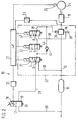
- FIG. 1 shows a section of a functional diagram of an electropneumatically or pneumatically actuated compressed air brake system with a relay valve that can be controlled by solenoid valves
- FIG. 2 shows a corresponding illustration with solenoid valves that differ from FIG.
- the first exemplary embodiment of a compressed air brake system 10 for commercial vehicles shown in FIG. 1 represents the activation of only one brake cylinder 11 in a brake line 12.
- the brake system 10 is of course used to actuate further brake cylinders, not shown, of the commercial vehicle.
- a compressed air reservoir 13 In the brake line 12 there is a compressed air reservoir 13.
- a relay valve 14 For monitoring the brake line 12, a relay valve 14, not shown in detail, is located between the reservoir 13 and the brake cylinder 11 for example of the type known from DE 32 40 274 C2.
- the brake system 10 has a pedal-operated, two-circuit brake value transmitter 17 with an electrical part 18 and a pneumatic part 19.
- Control unit 20 and control electronics 21 of an electrical primary control circuit for electropneumatic brake actuation, anti-lock and traction control operation are connected on the electrical part 18 of the brake value transmitter 17
- the control electronics 21 are used to actuate the solenoid valves described later in a pressure control unit 22 with a dash-dotted line in the drawing.
- a pressure sensor 23 which detects the brake pressure in the brake cylinder 11 and a rotational speed sensor 25 monitoring the rotational behavior of a vehicle wheel 24 braked by the brake cylinder 11 are connected to the control electronics 21.
- the pneumatic part 19 of the brake value transmitter 17 lies in a control line 28 of a pneumatic secondary control circuit of the brake system 10, branched off from the brake line 12 and supplied from the compressed air reservoir 13.
- the control line 28 leads to a control chamber 29 of the relay valve 14 integrated in the pressure control unit 22
- the pneumatic part 19 of the brake value transmitter 17, which has a pressure relief point 30, and the control chamber 29 of the relay valve 14, a changeover valve 31 are arranged in the control line 28 and a shutoff valve 32 is arranged downstream thereof.
- the switching valve 31 is designed as a 3/2-way valve. It has a spring-operated basic position 0, in which the control line 28 is switched through. In contrast, in a solenoid-operated working position I of the changeover valve 31, a supply line 35, which branches off from the brake line 12 between the compressed air supply container 13 and the relay valve 14, is connected to the downstream part of the control line 28. In the basic position 0 of the changeover valve 31, the supply line 35 is shut off; the upstream part of the control line 28 is also blocked in the working position I of the changeover valve 31.
- the shut-off valve 32 has the design of a 2/2-way valve. In its spring-operated open position 0, it switches through the control line 28; in the solenoid-operated blocking position I, however, the control line 28 is interrupted.
- a ventilation line 38 branches off from the control line 28, which leads to a pressure relief point 39 of the relay valve 14.
- An outlet valve 40 of the pressure control unit 22 is arranged in the vent line 38.
- the outlet valve 40 is designed as a 2/2-way valve: in its spring-operated blocking position 0, it interrupts the ventilation line 28, in the solenoid-operated opening position I the ventilation line 38 is switched on.
- a bypass line 43 is integrated in the pressure control unit 22. This bridges the shut-off valve 32 in the control line 28, i.e. the bypass line 43 is connected on the one hand between the changeover valve 31 and the shutoff valve 32 and on the other hand between the shutoff valve 32 and the control chamber 29 of the relay valve 14 to the control line 28.
- a check valve 44 is arranged in the bypass line 43 and opens in the flow direction from the control chamber 29 of the relay valve 14 to the changeover valve 31.
- the pressure controlled by the shut-off valve 32 and the outlet valve 40 in accordance with the electrical brake signal loads in the relay valve 14 a control piston for the actuation of a double seat valve, which monitors the connection between the compressed air reservoir 13 and the brake cylinder 11 or between the latter and the pressure relief point 39 on both sides of a closed position .
- the brake pressure controlled by the relay valve 14 is in turn monitored by the pressure sensor 23 and corrected in the event of deviations from the control electronics 21 by corresponding switching signals to the shut-off valve 32 and the outlet valve 40.
- control electronics 21 switches the shut-off valve 32 and the outlet valve 40 according to predetermined control algorithms for generating phases for brake pressure reduction, pressure maintenance and pressure build-up in the brake cylinder 11 in order to stabilize the vehicle wheel 24.
- control electronics 21 If impermissibly large drive slip occurs on the vehicle wheel 24 when the commercial vehicle starts up and accelerates, this is also recognized by the control electronics 21 on the basis of the signals from the speed sensor 25.
- the control electronics 21 then switch the changeover valve 31 to the working position I in order to supply the control line 28 with compressed air.
- the shut-off valve 32 and the outlet valve 40 are switched to generate phases for brake pressure build-up, pressure maintenance and pressure reduction in the brake cylinder 11.
- the pressure control unit 22 can be used in the braking system of a towing vehicle (as shown) and / or on a trailer vehicle. Activation of the relay valve 14 is also possible when there is no electrical brake signal, be it that the towing vehicle does not provide an electrical signal for the pressure control unit 22 located on the trailer vehicle or that the transmission of the electrical signal is not possible is what is recognized by the control unit 20 and / or the control electronics 21.
- the control electronics 21 therefore do not control the changeover valve 31, i.e. this remains in the basic position 0 just like the valves 32 and 40. Nevertheless, the braking ability of the compressed air brake system 10 is given, specifically via the pneumatic secondary control circuit also referred to as a retention circuit.
- the pneumatic brake signal which is actuated by the pneumatic part 19 when the brake value transmitter 17 is actuated, is fed through the control line 28 into the control chamber 29 of the relay valve 14 and the brake cylinder 11 is acted upon by the relay valve 14 with brake pressure.
- This can relate to pressure reduction the following
- the pressure hold phase, in which the shut-off valve 32 takes its locking position I and the exhaust valve 40 takes its locking position 0, can last for several seconds if an extremely low coefficient of friction on the road surface and a relatively large moment of inertia of the vehicle wheel 24 decelerates its acceleration.
- the second exemplary embodiment of the compressed air brake system 10 shown in FIG. 2 differs from the first one essentially in that a pressure control unit 22 'is equipped with a second changeover valve 47 which is arranged downstream of the shut-off valve 32 in the control line 28 and which functions as the outlet valve 40 of the with the first embodiment.
- the second switch valve 47 is a 3/2-way valve. In its spring-operated basic position 0, it switches through the control line 28 to the control chamber 29 of the relay valve 14. In its solenoid-operated working position I, the part of the control line 28 on the control chamber side is connected to the vent line 38 leading to the pressure relief point 39 of the relay valve 14.
- the connection of the vent line 38 is released, in the working position I the connection of the control line 28 is interrupted.
- the bypass line 43 bridges both the shut-off valve 32 and the second changeover valve 47 in the control line 28.
- shut-off valve 32 and the second switching valve 47 11 phases for pressure build-up, pressure maintenance and pressure reduction are in the brake cylinder switchable. No electrical control of the shut-off valve 32 and the second changeover valve 47 is required for brake pressure build-up. For pressure maintenance, only the shut-off valve 32 is to be switched to the solenoid-operated blocking position I. To lower the pressure, it is only necessary to switch the second changeover valve 47 into the solenoid-operated working position I.
- electropneumatic or purely pneumatic brake actuation and anti-lock and traction control operation are possible in a corresponding manner in the first exemplary embodiment.
Landscapes
- Engineering & Computer Science (AREA)
- Physics & Mathematics (AREA)
- Transportation (AREA)
- Mechanical Engineering (AREA)
- Fluid Mechanics (AREA)
- Electromagnetism (AREA)
- Braking Systems And Boosters (AREA)
- Regulating Braking Force (AREA)
Applications Claiming Priority (2)
| Application Number | Priority Date | Filing Date | Title |
|---|---|---|---|
| DE4141995 | 1991-12-19 | ||
| DE4141995A DE4141995A1 (de) | 1991-12-19 | 1991-12-19 | Druckluft-bremsanlage, insbesondere fuer nutzfahrzeuge |
Publications (2)
| Publication Number | Publication Date |
|---|---|
| EP0547407A1 true EP0547407A1 (fr) | 1993-06-23 |
| EP0547407B1 EP0547407B1 (fr) | 1996-03-06 |
Family
ID=6447509
Family Applications (1)
| Application Number | Title | Priority Date | Filing Date |
|---|---|---|---|
| EP92119947A Expired - Lifetime EP0547407B1 (fr) | 1991-12-19 | 1992-11-24 | Système de freinage à air comprimé, en particulier pour véhicules commerciales |
Country Status (2)
| Country | Link |
|---|---|
| EP (1) | EP0547407B1 (fr) |
| DE (2) | DE4141995A1 (fr) |
Cited By (17)
| Publication number | Priority date | Publication date | Assignee | Title |
|---|---|---|---|---|
| WO1995011823A2 (fr) * | 1993-10-29 | 1995-05-04 | Grau Limited | Systeme de freinage pour un vehicule |
| EP0659620A1 (fr) * | 1993-12-24 | 1995-06-28 | WABCO GmbH | Installation de soupape |
| FR2728849A1 (fr) * | 1994-12-31 | 1996-07-05 | Bosch Gmbh Robert | Procede destine a purger des cylindres de frein dans des installations de freinage pneumatiques a regulation du patinage |
| WO1997032767A1 (fr) * | 1996-03-09 | 1997-09-12 | Robert Bosch Gmbh | Valve de commande de remorque pour systeme de freinage a air comprime de vehicule a moteur |
| EP1028043A2 (fr) | 1999-02-11 | 2000-08-16 | WABCO GmbH & CO. OHG | Dispositif de commande de pression hydraulique |
| EP0994003A3 (fr) * | 1998-10-14 | 2001-05-30 | WABCO GmbH & Co. OHG | Dispositif de soupape |
| EP1132274A1 (fr) * | 2000-02-26 | 2001-09-12 | WABCO GmbH & CO. OHG | Modulateur de pression de freinage pour système de freinage electronique |
| WO2004022401A1 (fr) * | 2002-08-12 | 2004-03-18 | Knorr-Bremse Systeme Für Nutzfahrzeug Gmbh | Systeme de freinage electronique dote d'une fonction de rupture |
| DE10236920B4 (de) * | 2002-08-12 | 2005-09-29 | Knorr-Bremse Systeme für Nutzfahrzeuge GmbH | Elektronisches Bremssystem, insbesondere für Nutzfahrzeuganhänger |
| WO2010112879A1 (fr) * | 2009-04-01 | 2010-10-07 | Haldex Brake Products Limited | Système de commande de freinage |
| CN102159435B (zh) * | 2008-09-17 | 2014-02-12 | 克诺尔商用车制动系统有限公司 | 在损坏情况下运行驻车制动模块的方法和适于实施该方法的驻车制动模块 |
| EP1847432A3 (fr) * | 2006-04-21 | 2016-08-24 | KNORR-BREMSE Systeme für Schienenfahrzeuge GmbH | Dispositif de freinage direct d'un véhicule sur rail doté d'un régulateur électronique et d'un circuit électropneumatique supplémentaire |
| CN107512259A (zh) * | 2016-06-16 | 2017-12-26 | 南京理工大学 | 一种具有应急制动功能的商用车电子驻车系统 |
| CN108349468A (zh) * | 2015-11-28 | 2018-07-31 | 威伯科有限公司 | 用于车辆的压缩空气制动系统和用于对这种压缩空气制动系统进行控制的方法 |
| WO2019081101A1 (fr) * | 2017-10-26 | 2019-05-02 | Wabco Gmbh | Module de vanne d'essieu et module de vanne relais d'un système de freinage pneumatique |
| WO2019192863A1 (fr) * | 2018-04-05 | 2019-10-10 | Wabco Gmbh | Module de commande de freinage électro-pneumatique pour véhicules utilitaires comprenant un raccordement de pression redondante |
| US11691608B2 (en) * | 2017-10-04 | 2023-07-04 | Volvo Lastvagnar Ab | By-pass of air supply protection for electronic parking brake system and vehicle comprising such system |
Families Citing this family (3)
| Publication number | Priority date | Publication date | Assignee | Title |
|---|---|---|---|---|
| DE19536356B4 (de) * | 1995-09-29 | 2004-10-28 | Knorr-Bremse Systeme für Nutzfahrzeuge GmbH | Druckluft-Bremsanlage für Fahrzeuge, insbesondere Nutzfahrzeuge |
| DE19653263B4 (de) * | 1996-12-20 | 2010-04-08 | Knorr-Bremse Systeme für Nutzfahrzeuge GmbH | Elektronisch steuerbares Bremssystem für Fahrzeuge, insbesondere Nutzfahrzeuge |
| DE102013015972A1 (de) * | 2013-09-25 | 2015-03-26 | Wabco Gmbh | Elektronisch-pneumatische Bremsanlage, beispielsweise für einen Lastkraftwagen oder Lastzug |
Citations (4)
| Publication number | Priority date | Publication date | Assignee | Title |
|---|---|---|---|---|
| EP0110119A1 (fr) * | 1982-10-30 | 1984-06-13 | Robert Bosch Gmbh | Installation de freinage à fluide sous pression à plusieurs circuits |
| EP0163774A2 (fr) * | 1984-05-07 | 1985-12-11 | Robert Bosch Gmbh | Installation de freinage actionnée par pression pour véhicules |
| EP0307579B1 (fr) * | 1987-09-12 | 1991-03-20 | WABCO GmbH | Installation de valves commandées magnétiquement |
| DE4008095A1 (de) * | 1990-03-14 | 1991-09-19 | Bosch Gmbh Robert | Druckluftbremsanlage |
-
1991
- 1991-12-19 DE DE4141995A patent/DE4141995A1/de not_active Withdrawn
-
1992
- 1992-11-24 DE DE59205587T patent/DE59205587D1/de not_active Expired - Fee Related
- 1992-11-24 EP EP92119947A patent/EP0547407B1/fr not_active Expired - Lifetime
Patent Citations (4)
| Publication number | Priority date | Publication date | Assignee | Title |
|---|---|---|---|---|
| EP0110119A1 (fr) * | 1982-10-30 | 1984-06-13 | Robert Bosch Gmbh | Installation de freinage à fluide sous pression à plusieurs circuits |
| EP0163774A2 (fr) * | 1984-05-07 | 1985-12-11 | Robert Bosch Gmbh | Installation de freinage actionnée par pression pour véhicules |
| EP0307579B1 (fr) * | 1987-09-12 | 1991-03-20 | WABCO GmbH | Installation de valves commandées magnétiquement |
| DE4008095A1 (de) * | 1990-03-14 | 1991-09-19 | Bosch Gmbh Robert | Druckluftbremsanlage |
Cited By (32)
| Publication number | Priority date | Publication date | Assignee | Title |
|---|---|---|---|---|
| WO1995011823A3 (fr) * | 1993-10-29 | 1995-06-01 | Grau Ltd | Systeme de freinage pour un vehicule |
| WO1995011823A2 (fr) * | 1993-10-29 | 1995-05-04 | Grau Limited | Systeme de freinage pour un vehicule |
| EP0659620A1 (fr) * | 1993-12-24 | 1995-06-28 | WABCO GmbH | Installation de soupape |
| FR2728849A1 (fr) * | 1994-12-31 | 1996-07-05 | Bosch Gmbh Robert | Procede destine a purger des cylindres de frein dans des installations de freinage pneumatiques a regulation du patinage |
| US5733018A (en) * | 1994-12-31 | 1998-03-31 | Robert Bosch, Gmbh | System and method for venting brake cylinders in air brake systems subject to slip control |
| US6206481B1 (en) * | 1996-03-09 | 2001-03-27 | Knorr-Bremse | Trailer control valve for a compressed air brake system for motor vehicles |
| WO1997032767A1 (fr) * | 1996-03-09 | 1997-09-12 | Robert Bosch Gmbh | Valve de commande de remorque pour systeme de freinage a air comprime de vehicule a moteur |
| EP0994003A3 (fr) * | 1998-10-14 | 2001-05-30 | WABCO GmbH & Co. OHG | Dispositif de soupape |
| US6659129B1 (en) | 1998-10-14 | 2003-12-09 | Wabco Gmbh | Valve arrangement |
| EP1028043A2 (fr) | 1999-02-11 | 2000-08-16 | WABCO GmbH & CO. OHG | Dispositif de commande de pression hydraulique |
| EP1132274A1 (fr) * | 2000-02-26 | 2001-09-12 | WABCO GmbH & CO. OHG | Modulateur de pression de freinage pour système de freinage electronique |
| US6626505B2 (en) | 2000-02-26 | 2003-09-30 | Wabco Gmbh & Co. Ohg | Braking pressure modulator for an electronic braking system |
| WO2004022401A1 (fr) * | 2002-08-12 | 2004-03-18 | Knorr-Bremse Systeme Für Nutzfahrzeug Gmbh | Systeme de freinage electronique dote d'une fonction de rupture |
| DE10236921B4 (de) * | 2002-08-12 | 2005-09-29 | Knorr-Bremse Systeme für Nutzfahrzeuge GmbH | Elektronisches Bremssystem mit einer Abreissfunktion |
| DE10236920B4 (de) * | 2002-08-12 | 2005-09-29 | Knorr-Bremse Systeme für Nutzfahrzeuge GmbH | Elektronisches Bremssystem, insbesondere für Nutzfahrzeuganhänger |
| EP1847432A3 (fr) * | 2006-04-21 | 2016-08-24 | KNORR-BREMSE Systeme für Schienenfahrzeuge GmbH | Dispositif de freinage direct d'un véhicule sur rail doté d'un régulateur électronique et d'un circuit électropneumatique supplémentaire |
| CN102159435B (zh) * | 2008-09-17 | 2014-02-12 | 克诺尔商用车制动系统有限公司 | 在损坏情况下运行驻车制动模块的方法和适于实施该方法的驻车制动模块 |
| CN102369125A (zh) * | 2009-04-01 | 2012-03-07 | 霍尔德克斯制动产品有限公司 | 制动控制系统 |
| CN102369125B (zh) * | 2009-04-01 | 2015-07-08 | 霍尔德克斯制动产品有限公司 | 制动控制系统 |
| WO2010112879A1 (fr) * | 2009-04-01 | 2010-10-07 | Haldex Brake Products Limited | Système de commande de freinage |
| US8777332B2 (en) | 2009-04-01 | 2014-07-15 | Haldex Brake Products Limited | Braking control system |
| US10843673B2 (en) | 2015-11-28 | 2020-11-24 | Wabco Gmbh | Compressed air brake system for a vehicle and a method for controlling a compressed air brake system of this type |
| CN108349468A (zh) * | 2015-11-28 | 2018-07-31 | 威伯科有限公司 | 用于车辆的压缩空气制动系统和用于对这种压缩空气制动系统进行控制的方法 |
| CN108349468B (zh) * | 2015-11-28 | 2021-09-24 | 威伯科有限公司 | 用于车辆的压缩空气制动系统和用于对这种压缩空气制动系统进行控制的方法 |
| CN107512259A (zh) * | 2016-06-16 | 2017-12-26 | 南京理工大学 | 一种具有应急制动功能的商用车电子驻车系统 |
| US11691608B2 (en) * | 2017-10-04 | 2023-07-04 | Volvo Lastvagnar Ab | By-pass of air supply protection for electronic parking brake system and vehicle comprising such system |
| CN111247044A (zh) * | 2017-10-26 | 2020-06-05 | 威伯科有限公司 | 压缩空气制动设施的车轴阀模块和继动阀模块 |
| WO2019081101A1 (fr) * | 2017-10-26 | 2019-05-02 | Wabco Gmbh | Module de vanne d'essieu et module de vanne relais d'un système de freinage pneumatique |
| CN111247044B (zh) * | 2017-10-26 | 2022-06-03 | 威伯科有限公司 | 压缩空气制动设施的车轴阀模块和继动阀模块 |
| US11511719B2 (en) | 2017-10-26 | 2022-11-29 | Wabco Gmbh | Axle valve module and relay valve module of a compressed-air brake system |
| WO2019192863A1 (fr) * | 2018-04-05 | 2019-10-10 | Wabco Gmbh | Module de commande de freinage électro-pneumatique pour véhicules utilitaires comprenant un raccordement de pression redondante |
| US11440521B2 (en) | 2018-04-05 | 2022-09-13 | Wabco Gmbh | Electropneumatic brake control module for utility vehicles with redundancy pressure connector |
Also Published As
| Publication number | Publication date |
|---|---|
| DE4141995A1 (de) | 1993-06-24 |
| DE59205587D1 (de) | 1996-04-11 |
| EP0547407B1 (fr) | 1996-03-06 |
Similar Documents
| Publication | Publication Date | Title |
|---|---|---|
| EP0547407B1 (fr) | Système de freinage à air comprimé, en particulier pour véhicules commerciales | |
| DE102017118529B4 (de) | Elektronisch gesteuerte Anhänger-Bremssteuereinheit und Anhänger-Bremsanlage | |
| EP0883538B1 (fr) | Valve de commande de remorque pour systeme de freinage a air comprime de vehicule a moteur | |
| EP2059427B1 (fr) | Unité de soupape, dispositif de commande de freinage électropneumatique comprenant une unité de soupape de ce type pour la commande d'un frein de stationnement, système de freinage de véhicule comprenant un dispositif de commande de freinage de ce type et véhicule comprenant un tel système de freinage | |
| DE102016013054A1 (de) | Verfahren zum Einstellen von Bremsdrücken eines Fahrzeugs, Bremsanlage zur Durchführung des Verfahrens sowie Fahrzeug | |
| WO2019158351A1 (fr) | Équipement électropneumatique d'un véhicule | |
| DE10336611A1 (de) | Druckmittelbetriebene Bremsanlage für ein Fahrzeug | |
| EP3129264A1 (fr) | Dispositif de commande électropneumatique de frein de stationnement | |
| WO2002012040A1 (fr) | Frein de stationnement a commande electronique destine a un vehicule | |
| DE19653264A1 (de) | Elektronisch steuerbares Bremssystem für Fahrzeuge, insbesondere Nutzfahrzeuge | |
| DE102011012270A1 (de) | Antriebsschlupfgeregelte Bremsanlage eines Haltestellen anfahrenden Kraftfahrzeugs | |
| EP0478953B1 (fr) | Installation de freinage électro-pneumatique | |
| DE10038046B4 (de) | Stabilisierungseinrichtung für Kraftfahrzeuge mit druckluftbetriebenen Bremseinrichtungen | |
| WO2019081101A1 (fr) | Module de vanne d'essieu et module de vanne relais d'un système de freinage pneumatique | |
| DE2914165C2 (de) | Anordnung zum Verhindern des Durchdrehens einer oder mehrerer angetriebener Räder eines Fahrzeugs | |
| DE68907473T2 (de) | Hydraulischer Bremskreis für Kraftfahrzeuge mit Antiblockier- und Antischlupfeinrichtung. | |
| DE4004270A1 (de) | Bremsanlage | |
| EP0345203B1 (fr) | Installation de freinage avec moyen de pression régulé électroniquement | |
| DE19942533A1 (de) | Bremsvorrichtung für Fahrzeuge, insbesondere für druckluftgebremste Nutzfahrzeuge | |
| WO2001000470A1 (fr) | Systeme de freinage de vehicule a commande par fluide sous pression | |
| DE3545021A1 (de) | Elektro-pneumatische bremsanlage | |
| EP0442050B1 (fr) | Installation de freinage avec moyen de pression régulé électroniquement | |
| DE10042215C5 (de) | Druckmittelbetätigte Fahrzeugbremsanlage mit redundanter Ansteuerung wenigstens eines Bremszylinders | |
| DE3439067A1 (de) | Anordnung zum feststellen einer druckmittelbetaetigten radbremse | |
| DE3606085A1 (de) | Elektropneumatische bremseinrichtung fuer fahrzeuge |
Legal Events
| Date | Code | Title | Description |
|---|---|---|---|
| PUAI | Public reference made under article 153(3) epc to a published international application that has entered the european phase |
Free format text: ORIGINAL CODE: 0009012 |
|
| AK | Designated contracting states |
Kind code of ref document: A1 Designated state(s): DE FR GB SE |
|
| 17P | Request for examination filed |
Effective date: 19931125 |
|
| 17Q | First examination report despatched |
Effective date: 19941121 |
|
| GRAH | Despatch of communication of intention to grant a patent |
Free format text: ORIGINAL CODE: EPIDOS IGRA |
|
| GRAA | (expected) grant |
Free format text: ORIGINAL CODE: 0009210 |
|
| AK | Designated contracting states |
Kind code of ref document: B1 Designated state(s): DE FR GB SE |
|
| ET | Fr: translation filed | ||
| REF | Corresponds to: |
Ref document number: 59205587 Country of ref document: DE Date of ref document: 19960411 |
|
| GBT | Gb: translation of ep patent filed (gb section 77(6)(a)/1977) |
Effective date: 19960514 |
|
| PLBE | No opposition filed within time limit |
Free format text: ORIGINAL CODE: 0009261 |
|
| STAA | Information on the status of an ep patent application or granted ep patent |
Free format text: STATUS: NO OPPOSITION FILED WITHIN TIME LIMIT |
|
| 26N | No opposition filed | ||
| REG | Reference to a national code |
Ref country code: FR Ref legal event code: TP |
|
| REG | Reference to a national code |
Ref country code: GB Ref legal event code: 732E |
|
| REG | Reference to a national code |
Ref country code: GB Ref legal event code: IF02 |
|
| PGFP | Annual fee paid to national office [announced via postgrant information from national office to epo] |
Ref country code: SE Payment date: 20041105 Year of fee payment: 13 |
|
| PGFP | Annual fee paid to national office [announced via postgrant information from national office to epo] |
Ref country code: FR Payment date: 20041109 Year of fee payment: 13 |
|
| PGFP | Annual fee paid to national office [announced via postgrant information from national office to epo] |
Ref country code: DE Payment date: 20041118 Year of fee payment: 13 |
|
| PGFP | Annual fee paid to national office [announced via postgrant information from national office to epo] |
Ref country code: GB Payment date: 20041124 Year of fee payment: 13 |
|
| PG25 | Lapsed in a contracting state [announced via postgrant information from national office to epo] |
Ref country code: GB Free format text: LAPSE BECAUSE OF NON-PAYMENT OF DUE FEES Effective date: 20051124 |
|
| PG25 | Lapsed in a contracting state [announced via postgrant information from national office to epo] |
Ref country code: SE Free format text: LAPSE BECAUSE OF NON-PAYMENT OF DUE FEES Effective date: 20051125 |
|
| PG25 | Lapsed in a contracting state [announced via postgrant information from national office to epo] |
Ref country code: DE Free format text: LAPSE BECAUSE OF NON-PAYMENT OF DUE FEES Effective date: 20060601 |
|
| EUG | Se: european patent has lapsed | ||
| GBPC | Gb: european patent ceased through non-payment of renewal fee |
Effective date: 20051124 |
|
| PG25 | Lapsed in a contracting state [announced via postgrant information from national office to epo] |
Ref country code: FR Free format text: LAPSE BECAUSE OF NON-PAYMENT OF DUE FEES Effective date: 20060731 |
|
| REG | Reference to a national code |
Ref country code: FR Ref legal event code: ST Effective date: 20060731 |