EP0544893B1 - Terrain de football - Google Patents
Terrain de football Download PDFInfo
- Publication number
- EP0544893B1 EP0544893B1 EP92914234A EP92914234A EP0544893B1 EP 0544893 B1 EP0544893 B1 EP 0544893B1 EP 92914234 A EP92914234 A EP 92914234A EP 92914234 A EP92914234 A EP 92914234A EP 0544893 B1 EP0544893 B1 EP 0544893B1
- Authority
- EP
- European Patent Office
- Prior art keywords
- soccer
- facility
- playing area
- feet
- goal
- Prior art date
- Legal status (The legal status is an assumption and is not a legal conclusion. Google has not performed a legal analysis and makes no representation as to the accuracy of the status listed.)
- Expired - Lifetime
Links
Images


Classifications
-
- A—HUMAN NECESSITIES
- A63—SPORTS; GAMES; AMUSEMENTS
- A63C—SKATES; SKIS; ROLLER SKATES; DESIGN OR LAYOUT OF COURTS, RINKS OR THE LIKE
- A63C19/00—Design or layout of playing courts, rinks, bowling greens or areas for water-skiing; Covers therefor
- A63C19/06—Apparatus for setting-out or dividing courts
-
- A—HUMAN NECESSITIES
- A63—SPORTS; GAMES; AMUSEMENTS
- A63C—SKATES; SKIS; ROLLER SKATES; DESIGN OR LAYOUT OF COURTS, RINKS OR THE LIKE
- A63C19/00—Design or layout of playing courts, rinks, bowling greens or areas for water-skiing; Covers therefor
-
- A—HUMAN NECESSITIES
- A63—SPORTS; GAMES; AMUSEMENTS
- A63C—SKATES; SKIS; ROLLER SKATES; DESIGN OR LAYOUT OF COURTS, RINKS OR THE LIKE
- A63C19/00—Design or layout of playing courts, rinks, bowling greens or areas for water-skiing; Covers therefor
- A63C19/06—Apparatus for setting-out or dividing courts
- A63C19/08—Mechanical means for marking-out
- A63C2019/085—Fences; Nets; Barriers
Definitions
- the present invention relates to the art of sports playing areas, and particularly to soccer fields and courts.
- Soccer is an increasingly popular sport in the United States, especially among young people.
- the availability of soccer fields, however, is a problem. This is understandable, since a conventional outdoor soccer field is very large, on the order of 120 yards x 75 yards (110 m x 69 m), or roughly 9000 square yards (7525 m 2 ), upon which only one game of soccer can be played at a time. It will be appreciated that allocation of such a large space raises issues of use and expense, particularly in urban settings, resulting in few proper soccer facilities there. City dwellers must often travel long distances to play soccer, and have limited opportunities to play once they locate a field. Educational institutions must also balance the allocation of such large spaces to soccer fields against competing athletic uses and building sites.
- a conventional soccer game requires 22 players on the field. People who are interested in recreational play are disadvantaged because gathering that many people and coordinating them is often inconvenient. Many people interested in soccer are therefore relegated to constructing makeshift fields of smaller size to accommodate smaller groups, using whatever is at hand for goals, boundary lines, and the like. Much time is also spent chasing loose balls when they are kicked out of bounds. A ball kicked out of bounds can travel a great distance before coming to a stop.
- a common training technique for soccer teams is to mark a square in which two or three players practice techniques. Since such squares are usually in the middle of an open field, much chasing around after loose balls is necessary, which is especially disadvantageous because of the waste of time in a scheduled practice session.
- Another training technique employed by individuals or small numbers of soccer players is to kick the ball against a kickboard, which can consist of anything from a brick wall to a panel specially designed for such a purpose.
- Portable soccer playing areas could be advantageously employed in order to accommodate a touring group or provide a demonstration, or to enable more than one community to share the cost of construction of a soccer playing area while also sharing its benefits.
- EP-A-0455410 discloses a conventional soccer pitch, around which perimeter fencing is placed.
- the fencing comprises lower panels of solid or mesh material about 1 m high fixed between upright posts and upper panels of transparent material, the upper panels normally lying behind the lower panels but being pivotable into raised positions for crowd-contol purposes.
- a facility according to the invention can satisfy the above objects also be portable, and suitable for indoor or outdoor installation.
- the present invention provides a soccer playing facility comprising a playing area enclosed by side walls and end walls defining a substantially rectangular playing area , wherein said playing area is approximately 23.2 m (76 feet) to 28 m (92 feet) long and 9.75 m (32 feet) to 13.4 m (44 feet) wide, said side walls and end walls extend from the surface of the playing area to a height of approximately 1.8 m (6 feet) to 2.4 m (8 feet), and said side walls comprise a plurality of rigid transparent panels and supports for rigidly mounting said panels.
- the invention also provides a soccer playing facility according to claim 2.
- the supports for mounting the panels have a broad, heavy base attached which, instead of a permanent foundation, renders the soccer court portable.
- a preferred embodiment of the soccer court 10 comprises a substantially rectangular playing surface or area 20, two goals 30a and 30b, and an enclosing wall 40, comprising end walls 41 and side walls 42, disposed on the borders of the playing area 20.
- the playing area 20 is approximately 44 feet by 90 feet (13.4 m to 27.4 m) in the preferred embodiment.
- a tennis court which is no longer used, or one used with diminishing frequency, can be converted into a soccer court according to the present invention at minimum expense, since the necessary space has already been allocated and the foundation has already been flattened and prepared.
- the playing area 20 is disposed on a foundation 27 which may be covered by a variety of surfaces, including grass, clay, dirt, sand, concrete or asphalt, or artificial turf. It has been found that the latter is preferable because it adequately cushions players should they fall during play, and because it wears well and is relatively maintenance-free.
- suitable artificial turf include ASTROTURF® and AUTOGRAPH TURF®, manufactured by the Astroturf Company of St. Louis, Missouri. Grass is less preferable since it wears quickly, especially where the play is confined to a small area. Concrete or asphalt is also less preferable, since such surfaces are more likely to injure a player in a fall.
- the playing surface 20 is sloped or crowned slightly in the preferred embodiment to provide more effective drainage.
- the foundation 27 may comprise any suitable foundation known in the art, such as a concrete slab.
- the type of foundation will depend partially on the location; for example, if it is desired to erect the soccer court 10 on a beach (a common locale for impromptu soccer games), a preferred foundation would be a point foundation comprising concrete pier footings disposed underneath the wall 40, each footing being 12 to 18 inches (31 to 48 cm) in diameter and 4 to 6 feet (1.2 to 1.8 m) deep.
- the wall 40 comprises a plurality of rectangular panels 46 which are held in place by vertical structural members 44 and lower and upper horizontal structural members 43 and 45.
- the panels 46 are formed of rigid transparent material such as a clear polycarbonate.
- An example of the latter is LEXAN® material with MARGARD® surface treatment to provide a mar-resistant surface, manufactured by General Electric Corporation of Pittsfield, Massachusetts, with the panels being at least approximately 1/2 inches (13 mm) thick in the preferred embodiment.
- the transparent wall panels 46 will make the soccer court 10 relatively unobtrusive and more aesthetically pleasing in an outdoor environment. A transparent wall will also make the players feel less closed in and provide for convenient outside coaching and spectating.
- the structural members 43, 44, and 45 are preferably constructed of extruded aluminum.
- the wall 40 is approximately 6 feet-6 inches (2.0 m) to 7 feet (2.1 m) high in a preferred embodiment.
- the wall 40 may be of any height desired.
- to decrease construction costs it may be desired to lower the height of the side walls 42 to, e.g., approximately 2 feet-6 inches (0.76 m) since it is less likely that a ball will be kicked in the direction of, and thus escape over, the side walls 42 than the end walls 41. It may alternatively be desired to increase the height of the wall 40.
- both the side and end walls are constructed of rigid transparent panels thereby maximizing the sense of openness, spectator opportunity, and overall aesthetic appearance of the soccer court.
- the end walls 41 can be constructed of other materials such as masonry or wood.
- the side walls 42 can also be constructed of other material, if desired.
- the vertical members 44 are bolted to the foundation 27 by means of bolts or casing sleeves (not shown) which are cast into the foundation 27. Alternatively, the vertical members 44 can be secured to the foundation 27 by any other suitable means.
- the lower horizontal members 43 are bolted or welded or otherwise secured to the lower ends of the vertical members 44.
- the lower horizontal members 43 are U-shaped channels in the preferred embodiment, the rectangular panels 46 being placed between the upright arms of the channel.
- the lower horizontal members 43 are preferably disposed approximately 1/2 inch (13 mm) above the foundation 27 in one embodiment in order to allow for drainage. If desired, supports 49 can be placed at intervals between the lower horizontal members 43 and the foundation 27 and bolted into the latter to provide additional rigidity to the structure.
- the upper horizontal members 45 are preferably U-shaped channels and are bolted or welded to the upper ends of the vertical members 44 in such a manner that the channel is inverted and fits over the top of the rectangular panels 46.
- the horizontal members 43 and 45 are approximately four inches (10 cm) deep in a preferred embodiment.
- Fig. 4A shows an alternative configuration to provide for drainage.
- the foundation 27a under the playing surface 20 is raised slightly above the foundation 27b in the surrounding area.
- the raised playing surface 20 cooperates with a narrow drain channel 48 disposed between the playing surface 20 and the enclosing wall 40 to provide for drainage.
- the drain channel 48 is narrow, preferably one to three inches (8 cm) in width, so that should a player step on it, he will not turn his ankle or otherwise injure himself.
- a vertical structural member 44 which comprises a female connecting member 51 on the outside of the wall 40 and a mating T-shaped male connecting member 52 disposed on the inner side of the wall 40.
- a U-shaped receiving channel 53 extends along the length of the female connecting member 51 with two supports 54 protruding from its sides which face the male member 52.
- a latching pin 55 is disposed perpendicular to, and between the arms of, the channel 53.
- the T-shaped male connecting member 52 comprises a leg 56 and flanges 57.
- a slot 58 adapted to cooperatively engage latching pin 55, is disposed in the leg 56.
- the lower open portion of the slot 58 is at an angle to the vertical and relatively wide, while its upper portion is vertical and narrows to approximate the cross-sectional diameter of pin 55, which is firmly seated in the top of slot 58 when the two elements are securely engaged.
- the slanted lower portion of the slot 58 causes the male and female connecting members 52 and 51 to be drawn together as the latching pin 55 engages and enters the slot 58.
- the pin 55 enters the upper vertical portion of the slot 58, and the connecting members are locked together in an engaged relationship, as is shown in Fig. 6.
- the lower U-shaped horizontal member 43 is disposed at the lower end of the male connecting member 52 such that one arm 43a of the U-shaped channel is flush with the flanges 57 of male member 52.
- the other arm 43b is bolted, welded, or otherwise secured to the support 54 of the female connecting member 51.
- the upper U-shaped horizontal member 45 is oriented so that its open end faces downward and one arm 45a of the U-shaped channel is flush with the flanges 57 of the male member 52.
- the other arm 45b is secured to the support 54 of the female connecting member 51.
- a gap 59 equal in thickness to the arms 43b and 45b is created between the female connecting member 51 and the rectangular panel 46.
- the gap 59 is filled to ensure a flex-free fit between the panels 46 and the vertical member 44, preferably with a strip of neoprene or like material.
- the flanges 57 of the male connecting member 52 and the arms 43a and 45a of the lower and upper horizontal members protrude into the playing area 20 from the plane of the rectangular panels 46, causing the enclosing wall 40 to not be entirely smooth and flat.
- the interior surface of the wall can be made substantially flat or even, if desired, by casting the panels 46 with an appropriate recess along their edges, or by appropriately routing the edges of the panels to accommodate the retaining flanges and arms of the vertical and horizontal members. The same procedure may be followed to eliminate the gap 59, if desired.
- the vertical female connecting members 51 are bolted or otherwise secured to the foundation 27, and the arms 43b of the lower horizontal members 43 are bolted or otherwise secured to the lower portion of the vertical female members 51, and secured to the foundation 27 with supports 49.
- the panels 46 are then placed into the lower horizontal U-shaped channel members 43, and the gap 59 is filled.
- the vertical male connecting members 52 are then placed in engaging relationship with the female members 51 in the manner described above, and the arms 45b of the upper horizontal members 45 are bolted or otherwise secured to the upper portion of the vertical female members 51 to complete construction.
- Fig. 7 shows another embodiment of a vertical structural member 644, which comprises an outside connecting member 651 and an inside connecting member 652.
- the outside member 651 comprises a piece of rectangular tubing
- the inside T-shaped member 652 comprises a leg 656 and flanges 657, similar to the male connecting member 52 of Figs. 5 to 7.
- the outside and inside connecting members 651 and 652 are secured to each other by bolts 655 or other fasteners in order to retain the panels 46 and upper and lower horizontal members 45 and 43.
- the outer surface of member 651 is rounded to eliminate sharp projecting corners.
- Alternative forms of structural members and means of securing the wall panels will be apparent to those skilled in the art.
- player entrance doors 47 are disposed in side walls 42.
- the doors 47 are preferably constructed of transparent panels like the rest of the wall 40, and can be two feet wide.
- the doors are hung on adjacent vertical structural members by any suitable means, such as hinges.
- the precise location and number of the doors in the enclosing wall 40 is not critical.
- the goals 30a and 30b each comprise a goal opening 31 formed in the end walls 41.
- each goal opening 31 is the same height as the end wall, i.e., six feet-six inches (2.0 m) high, and is approximately twelve feet wide and framed by rigid sidebars 32 and a rigid crossbar 33.
- a goal net 34 is disposed behind the goal opening 31 and outside of the playing area. The edges of the goal net 34 are securely attached to the sidebars 32 and the crossbar 33 by any suitable means to form a ball retaining recess behind the plane of the end wall 41.
- a rectangular backstop retention net 35b is disposed above the end wall 41 to prevent errant balls, especially those kicked at the goals which are too high to enter, from escaping the soccer court 10.
- the net 35b can be from 6 to 10 feet high.
- a backstop retention net 35a is positioned above the end wall 41 and also further extends above sections of the adjacent side walls 42 to deflect balls back into the enclosure.
- doors 36b can be used to close the opening of goal 30b to create a kickboard practice area.
- the doors 36b are hinged to the sidebars 32 and disposed outside the soccer court 10. The doors 36b are closed by removing the goal net 34 and swinging the doors to a coplaner position with the end walls.
- the doors can comprise portable panels that can be placed in the goal opening 31 without having to remove the goal net 34.
- Other means can include bifolding doors which may fit into the goal net in the open position or sliding panels.
- the doors 36a and 36b can be used to create a smaller goal by closing only one door, turning half of the goal opening into a kickboard while leaving the other half open. Such an arrangement is useful for practicing precise goal shots.
- Outer boundary lines 21 can be marked on the playing surface 20 one or two feet from the side walls 42 and along the end walls 41 to the edges of the goals 30.
- the boundary lines 21 are optional; soccer can be played in the soccer court 10 either by using the boundary lines or by playing the ball off the enclosing wall 40. Even if the boundary lines are not used during games, they may be useful during drills, as discussed below. Lines are also marked on the playing surface 20 to form goal boxes 22 and larger penalty areas 23 immediately in front of the goals 30. A center line 24 and kickoff circle 25 can also be marked in the middle of the playing surface 20.
- an optional central divider 26 can be disposed over the center line 24 to divide the playing area 20 into two substantially square training areas 20a and 20b, permitting simultaneous use of the facility for two training sessions.
- the divider 26 is approximately 6 feet-6 inches (2.0 m) high in a preferred embodiment.
- the divider 26 is attached to the side walls 42 by any suitable means, and need not be at the center of the playing area 20 if, for example, it is desired to attach it to one of the vertical supports 44 adjacent to the entry doors 47.
- the divider 26 is a net in the preferred embodiment, but may comprise rigid boards or panels which, in cooperation with the doors 36a and 36b, would permit the entire periphery of each training area 20a,b to be used as a kickboard practice area.
- a door or other means for passage may be provided in the divider 26 to allow players to pass from one training area to another; for example, if the divider 26 is a net, the passage may comprise a flap attached with hook and loop VELCRO® fasteners.
- a common drill for players in training is to mark a square and conduct drills inside of it.
- the installation of a divider 26 creates two such training areas, using the boundary lines 21 and center line 24 for the training areas.
- balls kicked outside of the boundary lines 21 during such training do not have to be chased down since they will merely rebound from the wall 40.
- the goal 130 can be the same size in its outer dimensions as the goals 30a, or larger if it is desired to approximate the size of a regulation outdoor soccer goal.
- the goal 130 takes the shape of an inverted U.
- a rectangular blocking panel 140 is disposed in the center of the goal 130, leaving a goal opening 131 between the panel 140 and the sidebars 132 and crossbar 133 which define the outer dimensions of the goal 130.
- a goal net is secured behind the goal opening 131 as described above to retain balls kicked into the goal.
- the configuration of the goal 130 is intended to make scoring more challenging, and provides good practice for placing the ball into the upper and side areas or corners of the goal where the ball is less likely to be blocked by the goalkeeper.
- the difficulty of kicking a ball into the goal 130 allows effective play without a goalkeeper.
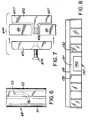
- FIG. 9 another embodiment of a soccer court 300 according to the invention is shown.
- the soccer court 300 is similar to the soccer court 10, except that the side and end walls 342 and 341 are joined by curved panels 301. This configuration can be used to preclude trapping of the soccer ball which may occur in a corner of the rectangular playing area of the soccer court 10.
- Fig. 10 shows a further embodiment of a soccer court 400 according to the invention in which the side and end walls 442 and 441 are joined by diagonal panels 401.
- the use of diagonal panels instead of the curved panels of Fig. 9 may be preferred for ease of manufacture and installation.
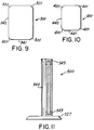
- the wall of a portable soccer court 500 is shown in cross-section.
- the vertical member 544 and lower horizontal member 543 are attached to a heavy and broad base 527 approximately three feet in width instead of to a permanent foundation.
- the base 527 may be moved from place to place, as desired.
- Sufficient width and weight of the base 527 can be selected to stabilize the wall 540, or the base 527 can additionally be secured to the ground, or to a floor if the portable soccer court is to be installed indoors.
- the portable soccer court 500 can be assembled from the same elements as described above in conjunction with the permanent installations.
- the court 500 can be divided into component parts that can be moved by hand or appropriate mechanical equipment in order to facilitate its disassembly, transportation, and relocation to another site.
Landscapes
- Engineering & Computer Science (AREA)
- Architecture (AREA)
- Civil Engineering (AREA)
- Structural Engineering (AREA)
- Road Paving Structures (AREA)
- Preparation Of Compounds By Using Micro-Organisms (AREA)
- Fencing (AREA)
Claims (39)
- Installation de terrain de football comprenant une aire de jeu fermée par des parois latérales (42) et des parois d'extrémité (41) définissant une aire de jeu sensiblement rectangulaire (20), dans laquelle ladite aire de jeu a approximativement une longueur de 23,2 m (76 pieds) à 28 m (92 pieds) et une largeur de 9,75 m (32 pieds) à 13,4 m (44 pieds), lesdites parois latérales (42) et parois d'extrémité (41) s'étendent depuis la surface de l'aire de jeu (20) jusqu'à une hauteur d'environ 1,8 m (6 pieds) à 2,4 m (8 pieds), et lesdites parois latérales comprennent une pluralité de panneaux transparents rigides (46) et de supports (43, 44, 45) sur lesquels lesdits panneaux sont montés de manière rigide.
- Installation de terrain de football comprenant une aire de jeu fermée par des parois latérales (42) et des parois d'extrémité (41) définissant une aire de jeu sensiblement rectangulaire (20), dans laquelle ladite aire de jeu est approximativement de la taille d'un court de tennis classique, lesdites parois latérales (42) et parois d'extrémité (41) s'étendent depuis la surface de l'aire de jeu (20) jusqu'à une hauteur d'environ 1,8 m (6 pieds) à 2,4 m (8 pieds), et lesdites parois latérales comprennent une pluralité de panneaux transparents rigides (46) et de supports (43, 44, 45) sur lesquels lesdits panneaux sont montés de manière rigide.
- Installation de football selon la revendication 1 ou 2, dans laquelle lesdits panneaux transparents (46) sont sensiblement rectangulaires, ont approximativement une hauteur de 2 m (six pieds six pouces), une largeur de 1,2 m (quatre pieds) et une épaisseur d'au moins 1,25 cm (0,5 pouce).
- Installation de football selon la revendication 1 ou 2, dans laquelle les panneaux transparents (46) sont construits en matériau polycarbonate transparent.
- Installation de football selon la revendication 4, dans laquelle les panneaux (46) sont traités pour fournir une surface résistant à l'abrasion.
- Installation de football selon la revendication 1 ou 2, dans laquelle les parois d'extrémité (41) comprennent des panneaux rigides transparents.
- Installation de football selon la revendication 1 ou 2, dans laquelle lesdits supports comprennent une pluralité d'éléments structurels horizontaux supérieurs (45), d'éléments structurels horizontaux inférieurs (43) et d'éléments structurels verticaux (44), agencés pour former une pluralité d'ouvertures rectangulaires, et dans laquelle lesdits panneaux transparents (46) sont placés dans lesdites ouvertures rectangulaires et sont maintenus en place par lesdits supports.
- Installation de football selon la revendication 7, dans laquelle lesdits éléments structurels horizontaux inférieurs (43) sont surélevés au-dessus de la surface de jeu (20) pour permettre le drainage.
- Installation de football selon la revendication 1 ou 2, comprenant en outre une porte d'entrée (47) disposée dans ladite paroi d'enceinte (40) pour l'entrée et la sortie des joueurs.
- Installation de football selon la revendication 1 ou 2, comprenant en outre une base lourde et large (527) fixée auxdits supports (543, 544).
- Installation de football selon la revendication 1 ou 2, dans laquelle ladite paroi d'enceinte a une surface intérieure sensiblement lisse.
- Installation de football selon la revendication 1 ou 2, comprenant en outre :une ouverture de cages (30a, 30b) disposée dans au moins une paroi d'extrémité (41) ; etun filet de cages (34) disposé derrière ladite ouverture de cages (30a, 30b) et en dehors de ladite aire de jeu (20).
- Installation de football selon la revendication 12, dans laquelle ladite aire de jeu (20) a approximativement une longueur de 27,4 m (90 pieds) et approximativement une largeur de 13,4 m (44 pieds).
- Installation de football selon la revendication 12, dans laquelle les parois d'extrémité (41) sont construites avec des panneaux transparents rigides.
- Installation de football selon la revendication 12, dans laquelle la périphérie extérieure de ladite ouverture de cages (130a, 130b) est définie par deux montants verticaux (132) et une barre transversale supérieure (133) et dans laquelle les dimensions intérieures de ladite ouverture de cages (130a, 130b) sont définies par un panneau rectangulaire (140) en contact avec la surface de l'aire de jeu (20) et centré sensiblement dans ladite périphérie extérieure, de manière à ce que ladite ouverture de cages ait sensiblement la forme d'un U renversé.
- Installation de football selon la revendication 12, comprenant en outre un filet de retenue arrière (35b) disposé verticalement au-dessus de la paroi d'extrémité (41) contenant l'ouverture de cages (30a, 30b).
- Installation de football selon la revendication 12, comprenant en outre un filet de retenue arrière (35b) s'étendant le long de la paroi d'extrémité (41) contenant l'ouverture de cages (30a, 30b) et en outre le long d'une partie des parois latérales adjacentes (42).
- Installation de football selon la revendication 12, dans laquelle l'aire de jeu (20) a un bombement.
- Installation de football selon la revendication 12, dans laquelle lesdites parois latérales (42) sont surélevées au-dessus de la surface de l'aire de jeu (20) pour faciliter le drainage.
- Installation de football selon la revendication 12, comprenant en outre un étroit canal de drainage (48) disposé entre ladite aire de jeu (20) et lesdites parois latérales (42) pour faciliter le drainage de ladite aire de jeu (20).
- Installation de football selon la revendication 1 ou 2, comprenant en outre :des moyens de division (26) disposés entre lesdites parois latérales (42) afin de séparer sélectivement ladite aire de jeu en une première et une deuxième aires d'entraínement rectilignes, de manière à ce que des sessions d'entraínement ou de jeu puissent se dérouler dans chaque aire d'entraínement indépendamment de l'autre.
- Installation de football selon la revendication 21, dans laquelle les aires d'entraínement forment des carrés d'environ 13,7 m (45 pieds) de côté.
- Installation de football selon la revendication 21, comprenant en outre une ouverture de cages (30a, 30b) disposée dans au moins une paroi d'extrémité (41) de ladite aire de jeu et des moyens (36b) pour fermer ladite ouverture de cages (30a, 30b) pour créer une aire d'entraínement au tir de coups de pied arrêtés.
- Installation de football selon la revendication 21, comprenant en outre une ouverture de cages disposée dans au moins une paroi d'extrémité de ladite aire de jeu, ladite ouverture de cages ayant la forme d'un U renversé.
- Installation de football selon la revendication 24, comprenant en outre des moyens (35b) pour éviter que les ballons tirés au-dessus de ladite ouverture de cages ne sortent de l'installation de football.
- Installation de football selon la revendication 25, dans laquelle lesdits moyens pour éviter que les ballons ne sortent du terrain de football comprennent un filet (35b) supporté au-dessus de la paroi d'enceinte (41, 42).
- Installation de football selon la revendication 21, dans laquelle la surface de ladite aire de jeu est recouverte de gazon artificiel.
- Installation de football selon la revendication 1 ou 2, comprenant en outre :au moins une porte (36b) disposée dans une paroi d'extrémité (41) qui, en position ouverte, assure une ouverture de cages (30b) et, en position fermée, assure une surface d'entraínement au tir de coups de pied arrêtés.
- Installation de football selon la revendication 28, dans laquelle ladite au moins une porte (36b) comprend un panneau amovible.
- Installation de football selon la revendication 28, dans laquelle ladite au moins une porte (36b) s'ouvre vers l'extérieur à l'opposé de l'aire de jeu (20) et se ferme vers l'intérieur vers l'aire de jeu (20).
- Installation de football selon la revendication 28, comprenant en outre une première porte (36b) et une deuxième porte (36b) adjacente à ladite première porte, de manière à fournir une ouverture de cages complètement ouverte lorsque lesdites première et deuxième portes sont en position ouverte, et de manière à fournir une ouverture de cages à demi ouverte lorsque l'une ou l'autre desdites première et deuxième portes (36b) est en position ouverte tandis que l'autre est en position fermée.
- Installation de football selon la revendication 28, dans laquelle ladite aire de jeu comprend deux aires d'entraínement adjacentes sensiblement carrées (20a, 20b) et une division (26) disposée entre lesdites aires d'entraínement.
- Installation de football selon la revendication 28, dans laquelle les parois latérales et d'extrémité sont jointes par des panneaux arrondis.
- Installation de football selon la revendication 28, dans laquelle les parois latérales et d'extrémité sont jointes par des panneaux en diagonale.
- Installation de football selon la revendication 12, dans laquelle une ouverture de cages d'environ 2 m (6 pieds 6 pouces) de hauteur et 3,7 m (12 pieds) de largeur est prévue dans chaque paroi d'extrémité (41) et un filet de cages (34) est disposé derrière chaque ouverture de cages.
- Installation de football selon la revendication 35, comprenant en outre une paroi portable pour diviser sélectivement ladite aire de jeu en deux aires d'entraínement sensiblement carrées.
- Installation de football selon la revendication 35, comprenant en outre des filets de retenue arrière d'environ 6 à 10 pieds de hauteur disposés au-dessus desdites parois d'extrémité.
- Installation de football selon la revendication 35, comprenant en outre des panneaux pour fermer sélectivement lesdites ouvertures de cages afin de former une aire d'entraínement au tir de coups de pied arrêtés.
- Installation de football selon la revendication 35, comprenant en outre des moyens pour éclairer ledit terrain de football.
Applications Claiming Priority (3)
| Application Number | Priority Date | Filing Date | Title |
|---|---|---|---|
| US07/719,022 US5312109A (en) | 1991-06-21 | 1991-06-21 | Soccer court |
| PCT/US1992/005213 WO1993000139A1 (fr) | 1991-06-21 | 1992-06-19 | Terrain de football ameliore |
| US719022 | 1996-09-24 |
Publications (3)
| Publication Number | Publication Date |
|---|---|
| EP0544893A1 EP0544893A1 (fr) | 1993-06-09 |
| EP0544893A4 EP0544893A4 (en) | 1993-10-20 |
| EP0544893B1 true EP0544893B1 (fr) | 1998-04-01 |
Family
ID=24888479
Family Applications (1)
| Application Number | Title | Priority Date | Filing Date |
|---|---|---|---|
| EP92914234A Expired - Lifetime EP0544893B1 (fr) | 1991-06-21 | 1992-06-19 | Terrain de football |
Country Status (7)
| Country | Link |
|---|---|
| US (1) | US5312109A (fr) |
| EP (1) | EP0544893B1 (fr) |
| AT (1) | ATE164529T1 (fr) |
| AU (1) | AU656797B2 (fr) |
| CA (1) | CA2089491A1 (fr) |
| DE (1) | DE69224968D1 (fr) |
| WO (1) | WO1993000139A1 (fr) |
Cited By (4)
| Publication number | Priority date | Publication date | Assignee | Title |
|---|---|---|---|---|
| DE102008008745A1 (de) | 2008-02-12 | 2009-08-13 | Usp Utilities For Sports And Propaganda Gmbh & Co. Kg | Anordnung für den Aufbau eines Kleinspielfelds |
| DE102008052636A1 (de) | 2008-10-22 | 2010-04-29 | Usp Holding Gmbh & Co. Kg | Anordnung für den Aufbau eines Kleinspielfelds |
| EP2208516A1 (fr) | 2009-01-20 | 2010-07-21 | USP Holding GmbH & Co. KG | palissade pour un petit terrain de jeu |
| EP2295121A1 (fr) | 2009-09-11 | 2011-03-16 | USP Holding GmbH & Co. KG | Agencement pour le montage d'un petit terrain de jeu |
Families Citing this family (52)
| Publication number | Priority date | Publication date | Assignee | Title |
|---|---|---|---|---|
| IT232319Y1 (it) * | 1994-02-07 | 1999-12-17 | Luigi Gigante | Campo da hit ball. impianto sportivo atto alla pratica della disciplina sportiva denominata hit ball. |
| US5647747A (en) * | 1995-01-20 | 1997-07-15 | Vincent J. Macri | Mechanized robots for use in instruction, training, and practice in the sport of ice and roller hockey |
| US5643094A (en) * | 1995-01-20 | 1997-07-01 | Macri; Vincent J. | Interactive ice and roller hockey training, coaching, and playing rinks |
| US5890906A (en) * | 1995-01-20 | 1999-04-06 | Vincent J. Macri | Method and apparatus for tutorial, self and assisted instruction directed to simulated preparation, training and competitive play and entertainment |
| DE19539280C1 (de) * | 1995-10-21 | 1997-02-06 | Erhard Leonhard Soehne | Spielfeldbegrenzung |
| US5599025A (en) * | 1996-04-12 | 1997-02-04 | Pobee-Mensah; Anthony | Methods and apparatus for playing a ball game |
| US5863266A (en) * | 1996-12-31 | 1999-01-26 | Usa Collegiate, L.P. | Soccer game with a plurality of goals |
| US5863030A (en) * | 1997-02-19 | 1999-01-26 | Dan Kotler | Dasher board |
| US5795252A (en) * | 1997-03-07 | 1998-08-18 | Crucet; Robert A. | Outfield wall structure for a baseball playing field |
| FR2768351B1 (fr) * | 1997-09-17 | 1999-12-03 | Oppidum Sarl | Parc multisports |
| EP1056523A1 (fr) | 1998-02-20 | 2000-12-06 | Eden Enterprises | Jeu de hockey en patins et patinoire pour le pratiquer |
| US6010416A (en) * | 1998-03-16 | 2000-01-04 | Frederick; John Garrett | Portable athletic field boundary |
| US6093109A (en) | 1998-07-09 | 2000-07-25 | Eden Enterprises | Rollercross-type rink design |
| US6402642B1 (en) | 1998-07-09 | 2002-06-11 | Eden Enterprises | Rollercross-type game and method thereof |
| USD430225S (en) * | 1998-07-10 | 2000-08-29 | Thomas David Waterman | Game playing surface |
| US6149529A (en) * | 1999-04-30 | 2000-11-21 | Hemisphere Group, Inc. | Combination football and skating game with enclosed ramp field and different scoring zones |
| DE29909729U1 (de) * | 1999-06-04 | 1999-11-18 | Heidlberger Frank | Vorrichtung eines Fußballspielfeldes mit Toren |
| DE19932815B4 (de) * | 1999-07-14 | 2005-12-15 | Erhard Sport International Gmbh & Co. | Spielfeldbegrenzung |
| US6676546B2 (en) | 2000-07-18 | 2004-01-13 | Time Warner Entertainment Company, L.P. | Game court for elevated goal ball game and game played thereon |
| GB2370994B (en) * | 2001-01-10 | 2004-06-02 | Alan Alderson | Ball game and court |
| GB0113553D0 (en) * | 2001-06-02 | 2001-07-25 | Heras Uk Fencing Systems Ltd | Ballcourt rebound panel |
| US20040058755A1 (en) * | 2002-09-19 | 2004-03-25 | Birks John R. | Court soccer |
| WO2004050198A1 (fr) * | 2002-12-03 | 2004-06-17 | Bellehumeur Alex R | Patinoire et procede de jeu |
| ES2281988B1 (es) * | 2004-04-30 | 2008-09-16 | Arquilago, S.L. | Cerramiento de cancha. |
| US20070021241A1 (en) * | 2005-07-25 | 2007-01-25 | Geller Jeffrey M | Method of playing a game, Triball, and an apparatus |
| US20070032317A1 (en) * | 2005-08-02 | 2007-02-08 | Frederick John G | Lining system |
| US20070049424A1 (en) * | 2005-08-25 | 2007-03-01 | Joseangel Hernandez-Ramil | Smashball |
| US20070072702A1 (en) * | 2005-09-29 | 2007-03-29 | Lion James M | Toeball - rules of the game |
| GB0610241D0 (en) * | 2006-05-24 | 2006-07-05 | J B Corrie And Company Ltd | Sports structures |
| WO2008064377A1 (fr) * | 2006-11-20 | 2008-05-29 | Kganyago Stephen Mabua | Aire de jeu et équipement de pratique du jeu |
| US7866104B2 (en) * | 2007-05-16 | 2011-01-11 | Asb-Systembau Horst Babinsky Gmbh | Base structure for squash courts |
| DE102008044939A1 (de) * | 2008-08-29 | 2010-04-01 | Ralf Esser | Bandensystem |
| GB0904617D0 (en) * | 2009-03-18 | 2009-04-29 | 1196501 Ontario Inc | Dasher-board system with flush-mounted glass |
| CN101554527B (zh) * | 2009-05-12 | 2011-06-15 | 宁波奇胜运动器材有限公司 | 笼式足球场 |
| USD707105S1 (en) | 2009-05-15 | 2014-06-17 | Sports Systems Unlimited Corp. | H style divider matrix sleeve |
| US20110028249A1 (en) * | 2009-07-31 | 2011-02-03 | Solomon Ofori-Ansah | Iso-Soccer |
| USD666247S1 (en) * | 2011-07-21 | 2012-08-28 | Fox Concepts Limited | Game board |
| DE202011105432U1 (de) | 2011-09-07 | 2011-12-06 | Kübler Sport GmbH | Gebäudekonstruktion zum Durchführen von Sportaktivitäten |
| WO2013143411A1 (fr) * | 2012-03-24 | 2013-10-03 | Wu Qiu | Terrain de sport pour sport de balle |
| US9057207B1 (en) | 2013-05-01 | 2015-06-16 | Kid Agains, Inc. | Multi-purpose recreational tent |
| US9194621B2 (en) * | 2014-02-25 | 2015-11-24 | The Thomas E. Smith Fight to Cure Paralysis Foundation | Skating rink markings and related methods |
| USD844809S1 (en) * | 2017-03-27 | 2019-04-02 | Drobyshau Dzianis Ivanovich | Playing field |
| US10112094B1 (en) * | 2017-04-21 | 2018-10-30 | Anthony D. Odorisio | Soccer training arena |
| US10926145B2 (en) | 2017-06-05 | 2021-02-23 | Chatem Llc | Soccer training devices, systems, and methods |
| US11484759B2 (en) | 2017-11-28 | 2022-11-01 | Kevin J. Brody | Basketball architecture |
| GB202217981D0 (en) | 2018-07-26 | 2023-01-11 | Musco Corp | Apparatus and method for design and installation of a customizable soccer mini-pitch system |
| USD929513S1 (en) * | 2018-12-10 | 2021-08-31 | 4 Fee Under Oy | Soccer game |
| AU2020260169A1 (en) * | 2019-04-19 | 2021-12-16 | Fritz VALDEUS | System for team ball game having interactive goal barriers |
| US10912975B1 (en) | 2019-05-03 | 2021-02-09 | Lycurgus Barnhill Ward | Extended skating rink and method of play thereon |
| US20210046372A1 (en) * | 2019-08-14 | 2021-02-18 | Soccer Park, LLC dba Urban Soccer Park | Modular Field |
| US11123622B1 (en) | 2021-04-01 | 2021-09-21 | Lycurgus Barnhill Ward | Extended skating rink and method of play thereon |
| USD1019861S1 (en) * | 2021-06-03 | 2024-03-26 | Smart Elvis Maumbe | Playing field |
Family Cites Families (14)
| Publication number | Priority date | Publication date | Assignee | Title |
|---|---|---|---|---|
| US959973A (en) * | 1910-01-12 | 1910-05-31 | Alfred Tomkins | Cage for games. |
| US2107141A (en) * | 1935-12-02 | 1938-02-01 | Colt George Herbert | Squash-racket court and the like |
| US2823034A (en) * | 1956-08-29 | 1958-02-11 | Jr Hiram Bingham | Recreation enclosure |
| US3779547A (en) * | 1971-06-30 | 1973-12-18 | Originetics Inc | Ball game court with heat receiving panel structure |
| US3872623A (en) * | 1974-03-25 | 1975-03-25 | Jr Charles A Spaulding | Entrance door construction for handball and racquetball courts |
| US3904193A (en) * | 1974-07-02 | 1975-09-09 | American Platform Tennis Syste | Platform tennis court |
| US4102101A (en) * | 1976-12-09 | 1978-07-25 | Harnee Pty. Ltd. | Glass panes, and buildings and the like including glass panes |
| US4167839A (en) * | 1976-12-09 | 1979-09-18 | World Squash And Racquetball Promotions Limited | Glass panes, and buildings and the like including glass panes |
| US4203594A (en) * | 1978-07-10 | 1980-05-20 | Cagle David G | Soccer court |
| US4284277A (en) * | 1978-09-11 | 1981-08-18 | Leonard David J | Kick ball game and apparatus kit therefor |
| US4497483A (en) * | 1981-10-21 | 1985-02-05 | Ahlgren Goeran | Device for dividing ice-hockey rinks |
| US4927134A (en) * | 1988-07-01 | 1990-05-22 | Burley's Ring Supply | Dasher board system |
| GB9010100D0 (en) * | 1990-05-04 | 1990-06-27 | Abacus Holdings Ltd | Barriers |
| FR2669834A1 (fr) * | 1990-12-04 | 1992-06-05 | Certec Sarl | Rambarde demontable pour patinoire. |
-
1991
- 1991-06-21 US US07/719,022 patent/US5312109A/en not_active Expired - Fee Related
-
1992
- 1992-06-19 DE DE69224968T patent/DE69224968D1/de not_active Expired - Lifetime
- 1992-06-19 WO PCT/US1992/005213 patent/WO1993000139A1/fr active IP Right Grant
- 1992-06-19 AU AU22532/92A patent/AU656797B2/en not_active Ceased
- 1992-06-19 CA CA002089491A patent/CA2089491A1/fr not_active Abandoned
- 1992-06-19 AT AT92914234T patent/ATE164529T1/de not_active IP Right Cessation
- 1992-06-19 EP EP92914234A patent/EP0544893B1/fr not_active Expired - Lifetime
Cited By (8)
| Publication number | Priority date | Publication date | Assignee | Title |
|---|---|---|---|---|
| DE102008008745A1 (de) | 2008-02-12 | 2009-08-13 | Usp Utilities For Sports And Propaganda Gmbh & Co. Kg | Anordnung für den Aufbau eines Kleinspielfelds |
| EP2090341A1 (fr) | 2008-02-12 | 2009-08-19 | USP Utilities for Sports & Propaganda GmbH & Co. KG | Agencement pour le montage d'un petit terrain de jeu |
| DE102008052636A1 (de) | 2008-10-22 | 2010-04-29 | Usp Holding Gmbh & Co. Kg | Anordnung für den Aufbau eines Kleinspielfelds |
| EP2208516A1 (fr) | 2009-01-20 | 2010-07-21 | USP Holding GmbH & Co. KG | palissade pour un petit terrain de jeu |
| DE102009005533A1 (de) | 2009-01-20 | 2010-07-22 | Usp Holding Gmbh & Co. Kg | Spielfeldbegrenzung für ein Kleinspielfeld |
| DE102009005533B4 (de) * | 2009-01-20 | 2020-01-30 | SoccerGround GmbH & Co. KG | Spielfeldbegrenzung für ein Kleinspielfeld |
| EP2295121A1 (fr) | 2009-09-11 | 2011-03-16 | USP Holding GmbH & Co. KG | Agencement pour le montage d'un petit terrain de jeu |
| DE102009040938A1 (de) | 2009-09-11 | 2011-03-17 | Usp Holding Gmbh & Co. Kg | Anordnung für den Aufbau eines Kleinspielfelds |
Also Published As
| Publication number | Publication date |
|---|---|
| CA2089491A1 (fr) | 1992-12-22 |
| EP0544893A1 (fr) | 1993-06-09 |
| DE69224968D1 (de) | 1998-05-07 |
| EP0544893A4 (en) | 1993-10-20 |
| ATE164529T1 (de) | 1998-04-15 |
| WO1993000139A1 (fr) | 1993-01-07 |
| AU2253292A (en) | 1993-01-25 |
| US5312109A (en) | 1994-05-17 |
| AU656797B2 (en) | 1995-02-16 |
Similar Documents
| Publication | Publication Date | Title |
|---|---|---|
| EP0544893B1 (fr) | Terrain de football | |
| CA2170198C (fr) | Systeme de panneaux muraux mobiles et methode d'utilisation correspondante | |
| US7001288B2 (en) | Soccer practice cage | |
| US5863030A (en) | Dasher board | |
| US5624122A (en) | Sport game and field | |
| US4957288A (en) | Putter pool billiard game | |
| US20060068946A1 (en) | Soccer practice cage | |
| US4973061A (en) | Indoor baseball game apparatus | |
| US4647046A (en) | Golf game | |
| US11857865B2 (en) | Portable multi-use ball pit | |
| US5346228A (en) | Soccer goal and gaming apparatus | |
| RU2009670C1 (ru) | Комплект для игры | |
| KR200357174Y1 (ko) | 이동식 실내 골프 연습장 | |
| EP2891510B1 (fr) | dispositif sportif escamotable | |
| Matthews | The University of Illinois Plans an Intramural-Physical Education Building | |
| KR200380728Y1 (ko) | 골프연습장치 | |
| US4966368A (en) | Geometric tennis lanes | |
| Carlson | Sharing Facilities | |
| KR20220142231A (ko) | 미니 파크골프장 어레이 | |
| RU1784249C (ru) | "Игра "Бильбол" | |
| EP0279995A1 (fr) | Dispositif pour jouer au golf | |
| Whitteker | A field house for Texas Tech University, Lubbock, Texas | |
| SPORTS | ATHLETICS AND RECREATION FACILITIES | |
| ZA200506883B (en) | A multi-purpose sports facility | |
| JPH09173522A (ja) | ゴルフ練習場 |
Legal Events
| Date | Code | Title | Description |
|---|---|---|---|
| PUAI | Public reference made under article 153(3) epc to a published international application that has entered the european phase |
Free format text: ORIGINAL CODE: 0009012 |
|
| AK | Designated contracting states |
Kind code of ref document: A1 Designated state(s): AT BE CH DE DK ES FR GB GR IT LI LU MC NL SE |
|
| 17P | Request for examination filed |
Effective date: 19930701 |
|
| A4 | Supplementary search report drawn up and despatched |
Effective date: 19930902 |
|
| AK | Designated contracting states |
Kind code of ref document: A4 Designated state(s): AT BE CH DE DK ES FR GB GR IT LI LU MC NL SE |
|
| 17Q | First examination report despatched |
Effective date: 19941025 |
|
| GRAG | Despatch of communication of intention to grant |
Free format text: ORIGINAL CODE: EPIDOS AGRA |
|
| GRAG | Despatch of communication of intention to grant |
Free format text: ORIGINAL CODE: EPIDOS AGRA |
|
| GRAH | Despatch of communication of intention to grant a patent |
Free format text: ORIGINAL CODE: EPIDOS IGRA |
|
| GRAH | Despatch of communication of intention to grant a patent |
Free format text: ORIGINAL CODE: EPIDOS IGRA |
|
| GRAA | (expected) grant |
Free format text: ORIGINAL CODE: 0009210 |
|
| AK | Designated contracting states |
Kind code of ref document: B1 Designated state(s): AT BE CH DE DK ES FR GB GR IT LI LU MC NL SE |
|
| PG25 | Lapsed in a contracting state [announced via postgrant information from national office to epo] |
Ref country code: NL Free format text: LAPSE BECAUSE OF FAILURE TO SUBMIT A TRANSLATION OF THE DESCRIPTION OR TO PAY THE FEE WITHIN THE PRESCRIBED TIME-LIMIT Effective date: 19980401 Ref country code: LI Free format text: LAPSE BECAUSE OF FAILURE TO SUBMIT A TRANSLATION OF THE DESCRIPTION OR TO PAY THE FEE WITHIN THE PRESCRIBED TIME-LIMIT Effective date: 19980401 Ref country code: IT Free format text: LAPSE BECAUSE OF FAILURE TO SUBMIT A TRANSLATION OF THE DESCRIPTION OR TO PAY THE FEE WITHIN THE PRE;WARNING: LAPSES OF ITALIAN PATENTS WITH EFFECTIVE DATE BEFORE 2007 MAY HAVE OCCURRED AT ANY TIME BEFORE 2007. THE CORRECT EFFECTIVE DATE MAY BE DIFFERENT FROM THE ONE RECORDED.SCRIBED TIME-LIMIT Effective date: 19980401 Ref country code: GR Free format text: LAPSE BECAUSE OF FAILURE TO SUBMIT A TRANSLATION OF THE DESCRIPTION OR TO PAY THE FEE WITHIN THE PRESCRIBED TIME-LIMIT Effective date: 19980401 Ref country code: FR Free format text: LAPSE BECAUSE OF FAILURE TO SUBMIT A TRANSLATION OF THE DESCRIPTION OR TO PAY THE FEE WITHIN THE PRESCRIBED TIME-LIMIT Effective date: 19980401 Ref country code: ES Free format text: THE PATENT HAS BEEN ANNULLED BY A DECISION OF A NATIONAL AUTHORITY Effective date: 19980401 Ref country code: CH Free format text: LAPSE BECAUSE OF FAILURE TO SUBMIT A TRANSLATION OF THE DESCRIPTION OR TO PAY THE FEE WITHIN THE PRESCRIBED TIME-LIMIT Effective date: 19980401 Ref country code: BE Free format text: LAPSE BECAUSE OF FAILURE TO SUBMIT A TRANSLATION OF THE DESCRIPTION OR TO PAY THE FEE WITHIN THE PRESCRIBED TIME-LIMIT Effective date: 19980401 Ref country code: AT Free format text: LAPSE BECAUSE OF FAILURE TO SUBMIT A TRANSLATION OF THE DESCRIPTION OR TO PAY THE FEE WITHIN THE PRESCRIBED TIME-LIMIT Effective date: 19980401 |
|
| REF | Corresponds to: |
Ref document number: 164529 Country of ref document: AT Date of ref document: 19980415 Kind code of ref document: T |
|
| REG | Reference to a national code |
Ref country code: CH Ref legal event code: EP |
|
| REF | Corresponds to: |
Ref document number: 69224968 Country of ref document: DE Date of ref document: 19980507 |
|
| PG25 | Lapsed in a contracting state [announced via postgrant information from national office to epo] |
Ref country code: LU Free format text: LAPSE BECAUSE OF NON-PAYMENT OF DUE FEES Effective date: 19980619 |
|
| PG25 | Lapsed in a contracting state [announced via postgrant information from national office to epo] |
Ref country code: SE Free format text: LAPSE BECAUSE OF FAILURE TO SUBMIT A TRANSLATION OF THE DESCRIPTION OR TO PAY THE FEE WITHIN THE PRESCRIBED TIME-LIMIT Effective date: 19980701 Ref country code: DK Free format text: LAPSE BECAUSE OF FAILURE TO SUBMIT A TRANSLATION OF THE DESCRIPTION OR TO PAY THE FEE WITHIN THE PRESCRIBED TIME-LIMIT Effective date: 19980701 |
|
| PG25 | Lapsed in a contracting state [announced via postgrant information from national office to epo] |
Ref country code: DE Free format text: LAPSE BECAUSE OF FAILURE TO SUBMIT A TRANSLATION OF THE DESCRIPTION OR TO PAY THE FEE WITHIN THE PRESCRIBED TIME-LIMIT Effective date: 19980702 |
|
| EN | Fr: translation not filed | ||
| NLV1 | Nl: lapsed or annulled due to failure to fulfill the requirements of art. 29p and 29m of the patents act | ||
| REG | Reference to a national code |
Ref country code: CH Ref legal event code: PL |
|
| PG25 | Lapsed in a contracting state [announced via postgrant information from national office to epo] |
Ref country code: MC Free format text: LAPSE BECAUSE OF NON-PAYMENT OF DUE FEES Effective date: 19981231 |
|
| PLBE | No opposition filed within time limit |
Free format text: ORIGINAL CODE: 0009261 |
|
| STAA | Information on the status of an ep patent application or granted ep patent |
Free format text: STATUS: NO OPPOSITION FILED WITHIN TIME LIMIT |
|
| 26N | No opposition filed | ||
| PGFP | Annual fee paid to national office [announced via postgrant information from national office to epo] |
Ref country code: GB Payment date: 20010718 Year of fee payment: 10 |
|
| REG | Reference to a national code |
Ref country code: GB Ref legal event code: IF02 |
|
| PG25 | Lapsed in a contracting state [announced via postgrant information from national office to epo] |
Ref country code: GB Free format text: LAPSE BECAUSE OF NON-PAYMENT OF DUE FEES Effective date: 20020619 |
|
| GBPC | Gb: european patent ceased through non-payment of renewal fee |
Effective date: 20020619 |