EP0541517A2 - A device for milking animals - Google Patents
A device for milking animals Download PDFInfo
- Publication number
- EP0541517A2 EP0541517A2 EP93200144A EP93200144A EP0541517A2 EP 0541517 A2 EP0541517 A2 EP 0541517A2 EP 93200144 A EP93200144 A EP 93200144A EP 93200144 A EP93200144 A EP 93200144A EP 0541517 A2 EP0541517 A2 EP 0541517A2
- Authority
- EP
- European Patent Office
- Prior art keywords
- milking
- milking parlour
- sensor members
- animal
- sensor
- Prior art date
- Legal status (The legal status is an assumption and is not a legal conclusion. Google has not performed a legal analysis and makes no representation as to the accuracy of the status listed.)
- Granted
Links
Images


Classifications
-
- A—HUMAN NECESSITIES
- A01—AGRICULTURE; FORESTRY; ANIMAL HUSBANDRY; HUNTING; TRAPPING; FISHING
- A01K—ANIMAL HUSBANDRY; CARE OF BIRDS, FISHES, INSECTS; FISHING; REARING OR BREEDING ANIMALS, NOT OTHERWISE PROVIDED FOR; NEW BREEDS OF ANIMALS
- A01K1/00—Housing animals; Equipment therefor
- A01K1/12—Milking stations
-
- A—HUMAN NECESSITIES
- A01—AGRICULTURE; FORESTRY; ANIMAL HUSBANDRY; HUNTING; TRAPPING; FISHING
- A01J—MANUFACTURE OF DAIRY PRODUCTS
- A01J5/00—Milking machines or devices
- A01J5/017—Automatic attaching or detaching of clusters
- A01J5/0175—Attaching of clusters
Definitions
- the invention relates to a device for milking animals comprising a milking parlour with a milking machine and positioning means for adjusting an animal to a position defined relative to a vertical plane in the longitudinal direction of the milking parlour, said positioning means including two sensor members being arranged near opposite longitudinal sides of the milking parlour.
- Such a device is known from US-A-4.010,714; specifically in the Figures 5 and 6 of this patent specification, sensor members are shown, which are attached to a scissors-like construction and movable in the lateral direction of the milking parlour by means of a motor-driven screw spindle.
- the invention aims to provide a self-positioning construction.
- each sensor member is pivotable about a respective shaft, said shafts being situated, seen in the pass-through direction of the milking parlour before a vertical plane through the end portions of the sensor members, the positioning means further being provided with a connecting rod which is movably connected with both sensor members, whereby the connection points of the connecting rod with the sensor members are situated at opposite sides of a plane through the shafts. So, the positioning means are provided with a rod brought in such a way between the sensor members that these sensor members can move together and synchroneously in- and outwards.
- a spring is provided to exert a force, directed to the vertical plane, on a sensor member; by means of such springs the sensor members are urged to move to a certain extent in the inward direction, so that an animal, present in the milking parlour, is forced to a position defined relative to a vertical plane in the longitudinal direction.
- the sensor members may be provided with a shoe which can bear against the animal's side.
- the sensor members are movably connected with a frame supporting teat cups.
- the frame is movable laterally relative to the milking parlour, thus realizing a movement of both sensor members from one side to another.
- the latter movability is realized by means of a parallelogram construction extending in a horizontal plane.
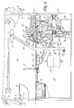
- Figures 1, 2 and 3 show a milking parlour in which a cow 1 may be present.
- the milking parlour is provided on either side with guide rails 2 and with guide rails 3, which may extend over the cow.
- the lateral guide rails 2 are fastened to the milking parlour wall.
- the upper guide rails 3 are adjustable for height in that they can swivel around the hinge points 4 and can be locked in different positions by means of blocking devices.
- the milking parlour has an entrance door 6 and an exit door 7.
- swivel arms 8 are provided which are connected capable of hinging to the frame or the wall of the device through hinge points 9 and also capable of swivelling to supports 10 fastened to the doors 6, 7.
- the doors 6 and 7 can be operated individually and automatically, for example hydraulically or pneumatically, through control means not further shown in the Figures 1, 2 and 3.
- a manger 11 is fastened to the exit door 7, in which doses of fodder, for example concentrated fodder, can be applied through means not further shown.
- doses of fodder for example concentrated fodder
- the entrance door 6 has a buffer 12, which - as is shown in Figure 2 - can bear against the posterior of the cow. Because of the presence of this buffer, the animal cannot move to the rear or the possibility to move to the rear can be limited. In this way the animal can be positioned in the longitudinal direction.
- FIG. 2 shows a flap 13, which is swivable around hinge pin 14 and is shown in its raised position.
- the flap 13 can be swivelled to a substantially horizontal position, the flap 13 then being flush with the floor 15 of the milking parlour.
- flap 13 When the animal enters the milking parlour, flap 13 will be in the position shown, and the animal will move its forelegs up to or near the flap 13, so as to be able ot reach the manger 11.
- the device has two sensor members 16, both provided with a shoe 17, which can bear against the animal's side.
- the mutual distance between the shoes 17 can be varied, but by means of a mechanism still further to be described in the sequel, the milking cluster 18 will always be in a central position below the two shoes 17.
- the two sensor members 16 are provided, each capable of hinging around a horizontal shaft 19, to a frame 20, which frame 20 can be moved laterally relative to the milking parlour because of the fact that it is supported by two parallel beams 21, each beam 21 being connected by means of one end and capable of hinging around a vertical shaft 22 to the frame 20 and by means of its other end, capable of hinging around vertical shaft 23 to the frame of the device.
- a parallelogram structure is obtained.
- the mutual motion of the sensor members 16 is coupled such that their motion can only proceed symmetrically relative to the frame 20.
- a connecting rod 24 is provided, one end 56 of which is connected capable of hinging to one sensor member, more specifically remote from hinge point 19, and by means of its other end 57 this rod 24 is connected to an extension 58 of the other sensor member at substantially the same distance from hinge point 19.
- a tension spring 25 is provided.
- the support 26 for the milking cluster is also connected to the frame 20, so that it can also be moved laterally by swivelling of the beams 21.
- the tension spring 25 moves the shoes 17 of the sensor members 16 to each other in such a way that the mutual distance between the shoes 17 is less than the width of an animal entering the milking parlour.
- the shoes will bear on both sides against the animal, the frame 20 always being moved to a position straight under the animal, as a result of which the milking cluster support 26 will always be central under the animal. Even if the animal moves during milking in a lateral direction, the milking cluster will follow this movement.
- the device can also include means for moving the sensor members 16 mutually from each other when the animal enters and/or leaves the milking parlour.
- the device furthermore includes a flap 27, which is swivable around a horizontal hinge pin 28, which extends substantially in the lateral direction relative to the milking parlour.
- the flap 27 will be in its horizontal position when it forms part of the floor 15 of the milking parlour, when the animal enters the milking parlour. Thereafter the flap 27 can be swivel led in the vertical direction, thus preventing the hindlegs of the animal, which are then up against or near the flap 27, from being capable of forward movement.
- this leg or both hindlegs will be compelled to move to the rear, which improves the accessibility of the udder. Because of the presence of guide rails 3 above the animal, the animal is prevented from trying to step over the flaps 13 or 27.
- FIG 1 four teat cups 29 of the milking cluster 18 are shown in plan view.
- the teat cups 29 are connected such to the support 26 by means of the horizontal hinge pin 30 that the cups of the milking cluster can rotate through 180°, whereafter they face down, cleaning means, such as a bowl-shaped basin 31 also having been rotated through 180° so that this basin has its open side face upward.
- the bowl-shaped basin 31 may be used for washing and cleaning the udder.
- the milking cluster 18 and the bowl-shaped basin 31 can move with their support 26 in the vertical direction, because the support 26 can move telescopically in the member 32 connected to the frame 20.
- Figure 2 furthermore shows a number of sensors, more specifically sensors 33 on the teat cups 29, which sensors can detect whether the connection of the teat cup to the teat of the udder is effected correctly. Sensors 34 can detect whether the hindlegs of the animal are in a correct position.
- control unit 35 and a microprocessor 36 are arranged below the milking parlour floor level.
- a control room 37 is also provided below the floor level of the milking parlour and a stair 38 is shown which gives access to the control room.
- Figure 4 shows schematically a stable in which a number of animals 40 move freely.
- the milking parlour 41 is incorporated in the stable and furthermore a door 42 is present, so that the stable is divided into two portion 43 and 44.
- Door 42 is freely swivable in one direction, so that the animals 40 can move through this door from portion 44 to portion 43 of the stable, but not vice versa.
- the animals can only move from portion 43 to portion 44 of the stable through the milking parlour 41, which, for that purpose has an entrance door 6 and an exit door 7.
- Figures 5 and 6 are cross-sectional views of a portion of the device for milking animals, which cross-sectional views show more details.
- the device includes guide rails 3 extending on both sides of the animal when the animal is in the milking parlour. In addition, in Figure 5 portions of guide rails 3 are shown, which guide rails may extend over the animal.
- the device furthermore has an entrance door 6 and an exit door 7, the entrance door 6 having a buffer 12 against which the posterior of the animal can bear, Door 7 is provided with a manger 11.
- a frame 20 is connected in such a way to a wall 45 by means of bars 21 that the frame 22 is capable of moving substantially in the lateral direction.
- two bars 21 are provided which are mutually in parallel and are each connected by means of one end to the wall 45, capable of hinging around a vertical axis, and by means of their other ends through a vertical hinge pin to the frame 22, so that a parallelogram construction is obtained.
- the sensor members 16 are fastened to the frame 22 and the support 26 is fastened through member 32.
- Member 32 constitutes a cylinder in which a piston 46 connected to a support 26 can move with the object of moving the milking cluster 18 in the vertical direction.
- the frame 22 supports two sensor members 16, which are both swivable, the connection being intercoupled by means of connecting rod 24.
- the sensor members 16 move the frame 22 such, that the milking cluster 18 is always in a central position under the two shoes 17 of sensor members 16.
- the milking cluster 18 which can move, by travelling in the vertical direction, to below the floor level of the milking parlour because a support 26 descends in element 32, has sensors 33 which can detect whether the teat cups 29 have been connected correctly to the teats of the udders.
- These sensors 33 as are also sensors 34 for detecting the position of the hindlegs of the animal, are connected by means of wires 47 to the control unit 35.
- this control unit 35 is conncted to the milking cluster 18, for producing the vacuum for the milking operation.
- the milk can flow to storage container 50 through conduit 49.
- control unit 35 provides for the motions of the different portions of the device. To that end, control unit 35 is connected through hydraulic conduits or air conduits 51 to a hydraulic or pneumatic cylinder 52 for operating flap 13 and to a hydraulic or pneumatic cylinder 53 for operating flap 27. Also the height adjustment of support 26 of milking cluster 18 may be effected hydraulically or pneumatically.
- the device includes a floor portion 54 which is capable of sliding in the longitudinal direction relative to the milking parlour.
- this floor portion 54 is connected to flap 27 and can be moved by means of a pneumatic or hydraulic cylinder 55.
- the hindlegs of the animal can be moved to the rear, so that the udder is accessible to an improved degree. In this situation, the buffer 12 can bear against the posterior of the animal.
- the milking cluster 18 can swivel around horizontal shaft 30, so that the bowl-shaped basin 31 is directed upwardly.
- cleaning of the animal's udder can be effected, for which purpose spray nozzles 60 and a liquid fed-forward through conduit 61 can be sprayed against the udder.
- This liquid may be a disinfectant, a rinsing agent in the form of warm water or any other liquid suitable for washing, rinsing, disinfecting or otherwise cleaning the udder.
- the bowl-shaped basin 31 has in its centre a discharge conduit 62 through which the used-up liquid can be discharged and through which optionally warm air can be blown to the udder for drying it.
- Figures 5 and 6 show, also schematically, a micro-processor or computer 36 which can control the device.
- This control may relate to connecting the milking cluster to the udder, decoupling the milking cluster from the udder, rinsing, cleaning or disinfecting the udder, positioning of the animal, metering of fodder, etc.
- the animal 1 may be provided with a collar 63 to which means 64 for identifying the animal are attached, so that using a sensor it can be detected which animal is present in the milking parlour, this information being used by the micro-processor 36 for controlling the device.
- sensors may alternatively be provided, for example sensors for determining the temperature of the milk, which data may be important for controlling the device.
- the relevant data of each animal can be stored in the memory of the micro-processor 36 and are thus available in any combination for a person operating the device.
Abstract
Description
- The invention relates to a device for milking animals comprising a milking parlour with a milking machine and positioning means for adjusting an animal to a position defined relative to a vertical plane in the longitudinal direction of the milking parlour, said positioning means including two sensor members being arranged near opposite longitudinal sides of the milking parlour.
- Such a device is known from US-A-4.010,714; specifically in the Figures 5 and 6 of this patent specification, sensor members are shown, which are attached to a scissors-like construction and movable in the lateral direction of the milking parlour by means of a motor-driven screw spindle. Instead of motor-driven positioning means, the invention aims to provide a self-positioning construction.
- To that end, the device according to the invention is characterized in that each sensor member is pivotable about a respective shaft, said shafts being situated, seen in the pass-through direction of the milking parlour before a vertical plane through the end portions of the sensor members, the positioning means further being provided with a connecting rod which is movably connected with both sensor members, whereby the connection points of the connecting rod with the sensor members are situated at opposite sides of a plane through the shafts. So, the positioning means are provided with a rod brought in such a way between the sensor members that these sensor members can move together and synchroneously in- and outwards. Further, in accordance with the invention a spring is provided to exert a force, directed to the vertical plane, on a sensor member; by means of such springs the sensor members are urged to move to a certain extent in the inward direction, so that an animal, present in the milking parlour, is forced to a position defined relative to a vertical plane in the longitudinal direction. The sensor members may be provided with a shoe which can bear against the animal's side.
- In a specific embodiment, the sensor members are movably connected with a frame supporting teat cups. Thereby it is advantageously to provide the above-mentioned springs between the sensor members and this frame. Apart from the possibility that the sensor members can move together and synchroneously in- and outwards, the frame is movable laterally relative to the milking parlour, thus realizing a movement of both sensor members from one side to another. In a specific embodiment, the latter movability is realized by means of a parallelogram construction extending in a horizontal plane.
- For a better understanding of the invention, an embodiment of a device for milking animals will now be described, by way of example, with reference to the drawing.
- Figure 1 is a plan view of the device;
- Figure 2 is a side elevational view of the device, partly in cross-section;
- Figure 3 is a cross-sectional view along the line III-III of Figure 2;
- Figure 4 shows a set-up of the device;
- Figure 5 shows a number of details of the device, shown in plan view and
- Figure 6 shows details by means of a cross-sectional view along the line VI-VI of Figure 5.
- The Figures are shown schematically, corresponding components having been given the same reference numerals.
- Figures 1, 2 and 3 show a milking parlour in which a
cow 1 may be present. The milking parlour is provided on either side with guide rails 2 and withguide rails 3, which may extend over the cow. The lateral guide rails 2 are fastened to the milking parlour wall. Theupper guide rails 3 are adjustable for height in that they can swivel around thehinge points 4 and can be locked in different positions by means of blocking devices. - In addition, the milking parlour has an
entrance door 6 and an exit door 7. To open the doors,swivel arms 8 are provided which are connected capable of hinging to the frame or the wall of the device throughhinge points 9 and also capable of swivelling to supports 10 fastened to thedoors 6, 7. Thedoors 6 and 7 can be operated individually and automatically, for example hydraulically or pneumatically, through control means not further shown in the Figures 1, 2 and 3. - A
manger 11 is fastened to the exit door 7, in which doses of fodder, for example concentrated fodder, can be applied through means not further shown. - The
entrance door 6 has abuffer 12, which - as is shown in Figure 2 - can bear against the posterior of the cow. Because of the presence of this buffer, the animal cannot move to the rear or the possibility to move to the rear can be limited. In this way the animal can be positioned in the longitudinal direction. - Figure 2 shows a
flap 13, which is swivable aroundhinge pin 14 and is shown in its raised position. Theflap 13 can be swivelled to a substantially horizontal position, theflap 13 then being flush with thefloor 15 of the milking parlour. When the animal enters the milking parlour,flap 13 will be in the position shown, and the animal will move its forelegs up to or near theflap 13, so as to be able ot reach themanger 11. - Additionally, the device has two
sensor members 16, both provided with a shoe 17, which can bear against the animal's side. The mutual distance between the shoes 17 can be varied, but by means of a mechanism still further to be described in the sequel, themilking cluster 18 will always be in a central position below the two shoes 17. To that end, the twosensor members 16 are provided, each capable of hinging around ahorizontal shaft 19, to aframe 20, whichframe 20 can be moved laterally relative to the milking parlour because of the fact that it is supported by twoparallel beams 21, eachbeam 21 being connected by means of one end and capable of hinging around avertical shaft 22 to theframe 20 and by means of its other end, capable of hinging aroundvertical shaft 23 to the frame of the device. Thus a parallelogram structure is obtained. The mutual motion of thesensor members 16 is coupled such that their motion can only proceed symmetrically relative to theframe 20. For that purpose a connectingrod 24 is provided, oneend 56 of which is connected capable of hinging to one sensor member, more specifically remote fromhinge point 19, and by means of itsother end 57 thisrod 24 is connected to anextension 58 of the other sensor member at substantially the same distance fromhinge point 19. So as to pull the twosensor members 16 slightly towards each other, atension spring 25 is provided. Thesupport 26 for the milking cluster is also connected to theframe 20, so that it can also be moved laterally by swivelling of thebeams 21. - The
tension spring 25 moves the shoes 17 of thesensor members 16 to each other in such a way that the mutual distance between the shoes 17 is less than the width of an animal entering the milking parlour. As a result thereof, the shoes will bear on both sides against the animal, theframe 20 always being moved to a position straight under the animal, as a result of which themilking cluster support 26 will always be central under the animal. Even if the animal moves during milking in a lateral direction, the milking cluster will follow this movement. - The device can also include means for moving the
sensor members 16 mutually from each other when the animal enters and/or leaves the milking parlour. - The device furthermore includes a
flap 27, which is swivable around ahorizontal hinge pin 28, which extends substantially in the lateral direction relative to the milking parlour. Theflap 27 will be in its horizontal position when it forms part of thefloor 15 of the milking parlour, when the animal enters the milking parlour. Thereafter theflap 27 can be swivel led in the vertical direction, thus preventing the hindlegs of the animal, which are then up against or near theflap 27, from being capable of forward movement. When one or both hind legs of the animal would originally stand on the flap, this leg or both hindlegs will be compelled to move to the rear, which improves the accessibility of the udder. Because of the presence ofguide rails 3 above the animal, the animal is prevented from trying to step over theflaps - In Figure 1 four
teat cups 29 of themilking cluster 18 are shown in plan view. As will be clear from the Figures 2 and 3, theteat cups 29 are connected such to thesupport 26 by means of thehorizontal hinge pin 30 that the cups of the milking cluster can rotate through 180°, whereafter they face down, cleaning means, such as a bowl-shaped basin 31 also having been rotated through 180° so that this basin has its open side face upward. The bowl-shaped basin 31 may be used for washing and cleaning the udder. - The
milking cluster 18 and the bowl-shaped basin 31 can move with theirsupport 26 in the vertical direction, because thesupport 26 can move telescopically in themember 32 connected to theframe 20. - Figure 2 furthermore shows a number of sensors, more specifically
sensors 33 on theteat cups 29, which sensors can detect whether the connection of the teat cup to the teat of the udder is effected correctly.Sensors 34 can detect whether the hindlegs of the animal are in a correct position. - In addition, a control unit denoted by
reference numeral 35 and amicroprocessor 36 are arranged below the milking parlour floor level. - As is shown in Figure 3, a
control room 37 is also provided below the floor level of the milking parlour and astair 38 is shown which gives access to the control room. - Figure 4 shows schematically a stable in which a number of
animals 40 move freely. Themilking parlour 41 is incorporated in the stable and furthermore adoor 42 is present, so that the stable is divided into twoportion Door 42 is freely swivable in one direction, so that theanimals 40 can move through this door fromportion 44 toportion 43 of the stable, but not vice versa. The animals can only move fromportion 43 toportion 44 of the stable through themilking parlour 41, which, for that purpose has anentrance door 6 and an exit door 7. - Figures 5 and 6 are cross-sectional views of a portion of the device for milking animals, which cross-sectional views show more details. The device includes
guide rails 3 extending on both sides of the animal when the animal is in the milking parlour. In addition, in Figure 5 portions ofguide rails 3 are shown, which guide rails may extend over the animal. The device furthermore has anentrance door 6 and an exit door 7, theentrance door 6 having abuffer 12 against which the posterior of the animal can bear, Door 7 is provided with amanger 11. - A
frame 20 is connected in such a way to awall 45 by means ofbars 21 that theframe 22 is capable of moving substantially in the lateral direction. To that end, twobars 21 are provided which are mutually in parallel and are each connected by means of one end to thewall 45, capable of hinging around a vertical axis, and by means of their other ends through a vertical hinge pin to theframe 22, so that a parallelogram construction is obtained. Thesensor members 16 are fastened to theframe 22 and thesupport 26 is fastened throughmember 32.Member 32 constitutes a cylinder in which apiston 46 connected to asupport 26 can move with the object of moving the milkingcluster 18 in the vertical direction. - Furthermore, the
frame 22 supports twosensor members 16, which are both swivable, the connection being intercoupled by means of connectingrod 24. As has already been described in the foregoing, thesensor members 16 move theframe 22 such, that the milkingcluster 18 is always in a central position under the two shoes 17 ofsensor members 16. The milkingcluster 18 which can move, by travelling in the vertical direction, to below the floor level of the milking parlour because asupport 26 descends inelement 32, hassensors 33 which can detect whether the teat cups 29 have been connected correctly to the teats of the udders. Thesesensors 33, as are alsosensors 34 for detecting the position of the hindlegs of the animal, are connected by means of wires 47 to thecontrol unit 35. By means of conduit 48, thiscontrol unit 35 is conncted to the milkingcluster 18, for producing the vacuum for the milking operation. The milk can flow tostorage container 50 through conduit 49. - In addition,
control unit 35 provides for the motions of the different portions of the device. To that end,control unit 35 is connected through hydraulic conduits or air conduits 51 to a hydraulic orpneumatic cylinder 52 for operatingflap 13 and to a hydraulic orpneumatic cylinder 53 for operatingflap 27. Also the height adjustment ofsupport 26 of milkingcluster 18 may be effected hydraulically or pneumatically. - Additionally, the device includes a
floor portion 54 which is capable of sliding in the longitudinal direction relative to the milking parlour. By means ofhinge 28 thisfloor portion 54 is connected toflap 27 and can be moved by means of a pneumatic orhydraulic cylinder 55. By moving thefloor portion 54 rearwardly, the hindlegs of the animal can be moved to the rear, so that the udder is accessible to an improved degree. In this situation, thebuffer 12 can bear against the posterior of the animal. - As is shown in Figure 6, the milking
cluster 18 can swivel aroundhorizontal shaft 30, so that the bowl-shapedbasin 31 is directed upwardly. In this position ofbasin 31, cleaning of the animal's udder can be effected, for whichpurpose spray nozzles 60 and a liquid fed-forward through conduit 61 can be sprayed against the udder. This liquid may be a disinfectant, a rinsing agent in the form of warm water or any other liquid suitable for washing, rinsing, disinfecting or otherwise cleaning the udder. The bowl-shapedbasin 31 has in its centre adischarge conduit 62 through which the used-up liquid can be discharged and through which optionally warm air can be blown to the udder for drying it. - Figures 5 and 6 show, also schematically, a micro-processor or
computer 36 which can control the device. This control may relate to connecting the milking cluster to the udder, decoupling the milking cluster from the udder, rinsing, cleaning or disinfecting the udder, positioning of the animal, metering of fodder, etc. Then, theanimal 1 may be provided with acollar 63 to which means 64 for identifying the animal are attached, so that using a sensor it can be detected which animal is present in the milking parlour, this information being used by the micro-processor 36 for controlling the device. - Further sensors may alternatively be provided, for example sensors for determining the temperature of the milk, which data may be important for controlling the device. The relevant data of each animal can be stored in the memory of the micro-processor 36 and are thus available in any combination for a person operating the device.
Claims (7)
- A device for milking animals, such as cows, comprising a milking parlour with a milking machine and positioning means for adjusting an animal (1) to a position defined relative to a vertical plane in the longitudinal direction of the milking parlour, said positioning means including two sensor members (16) being arranged near opposite longitudinal sides of the milking parlour, characterized in that each sensor member (16) is pivotable about a respective shaft (19), said shafts (19) being situated, seen in the pass-through direction of the milking parlour before a vertical plane through the end portions of the sensor members (16), the positioning means further being provided with a connecting rod (24) which is movably connected with both sensor members (16), whereby the connection points of the connecting rod (24) with the sensor members (16) are situated at opposite sides of a plane through the shafts (19).
- A device as claimed in claim 1, characterized in that a spring (25) is provided to exert a force, directed to the vertical plane, on a sensor member (16).
- A device as claimed in claim 1 or 2, characterized in that a sensor member (16) is provided with a shoe (17) which can bear against the animal's side.
- A device as claimed in any one of the preceding claims, characterized in that the sensor members (16) are movably connected with a frame (20) supporting teat cups (29).
- A device as claimed in claim 4, characterized in that between each of the sensor members (16) and the frame (20) a spring (25) is provided.
- A device as claimed in claim 4 or 5, characterized in that the frame (20) is movable laterally relative to the milking parlour.
- A device as claimed in claim 6, characterized in that the frame is movable relative to the milking parlour by means of a parallelogram construction extending in a horizontal plane.
Applications Claiming Priority (7)
| Application Number | Priority Date | Filing Date | Title |
|---|---|---|---|
| NL8500223A NL192074C (en) | 1985-01-28 | 1985-01-28 | Device for milking animals, such as cows. |
| NL8500222A NL8500222A (en) | 1985-01-28 | 1985-01-28 | Animal milking appts. e.g. for cow - measures whether milking cluster is correctly attached to udder |
| NL8500222 | 1985-01-28 | ||
| NL8500224 | 1985-01-28 | ||
| NL8500224A NL192317C (en) | 1985-01-28 | 1985-01-28 | Method for milking animals, such as cows. |
| NL8500223 | 1985-01-28 | ||
| EP89103332A EP0322404B1 (en) | 1985-01-28 | 1986-01-22 | A device for milking animals, such as cows |
Related Parent Applications (1)
| Application Number | Title | Priority Date | Filing Date |
|---|---|---|---|
| EP89103332.6 Division | 1986-01-22 |
Publications (3)
| Publication Number | Publication Date |
|---|---|
| EP0541517A2 true EP0541517A2 (en) | 1993-05-12 |
| EP0541517A3 EP0541517A3 (en) | 1993-10-06 |
| EP0541517B1 EP0541517B1 (en) | 1997-06-11 |
Family
ID=27352123
Family Applications (2)
| Application Number | Title | Priority Date | Filing Date |
|---|---|---|---|
| EP93200144A Expired - Lifetime EP0541517B1 (en) | 1985-01-28 | 1986-01-22 | A device for milking animals |
| EP86200099A Expired - Lifetime EP0191517B2 (en) | 1985-01-28 | 1986-01-22 | Implement for milking animals, such as cows |
Family Applications After (1)
| Application Number | Title | Priority Date | Filing Date |
|---|---|---|---|
| EP86200099A Expired - Lifetime EP0191517B2 (en) | 1985-01-28 | 1986-01-22 | Implement for milking animals, such as cows |
Country Status (3)
| Country | Link |
|---|---|
| EP (2) | EP0541517B1 (en) |
| AT (2) | ATE108299T1 (en) |
| DE (4) | DE3689972T2 (en) |
Cited By (26)
| Publication number | Priority date | Publication date | Assignee | Title |
|---|---|---|---|---|
| US5718185A (en) * | 1994-06-09 | 1998-02-17 | Alfa Laval Agri Ab | Herringbone-type rotary milking parlour |
| NL1006171C2 (en) * | 1997-05-30 | 1998-12-01 | Maasland Nv | Construction with a device for automatic milking of animals. |
| KR100479120B1 (en) * | 2002-06-17 | 2005-03-25 | 대한민국(관리부서:농촌진흥청) | The stall system for automatic milking system |
| US8393296B2 (en) | 2011-04-28 | 2013-03-12 | Technologies Holdings Corp. | Milking box with robotic attacher including rotatable gripping portion and nozzle |
| US8590488B2 (en) | 2010-08-31 | 2013-11-26 | Technologies Holdings Corp. | Vision system for facilitating the automated application of disinfectant to the teats of dairy livestock |
| US8671885B2 (en) | 2011-04-28 | 2014-03-18 | Technologies Holdings Corp. | Vision system for robotic attacher |
| US8683946B2 (en) | 2011-04-28 | 2014-04-01 | Technologies Holdings Corp. | System and method of attaching cups to a dairy animal |
| US8746176B2 (en) | 2011-04-28 | 2014-06-10 | Technologies Holdings Corp. | System and method of attaching a cup to a dairy animal according to a sequence |
| US8800487B2 (en) | 2010-08-31 | 2014-08-12 | Technologies Holdings Corp. | System and method for controlling the position of a robot carriage based on the position of a milking stall of an adjacent rotary milking platform |
| US8885891B2 (en) | 2011-04-28 | 2014-11-11 | Technologies Holdings Corp. | System and method for analyzing data captured by a three-dimensional camera |
| US8903129B2 (en) | 2011-04-28 | 2014-12-02 | Technologies Holdings Corp. | System and method for filtering data captured by a 2D camera |
| US9043988B2 (en) | 2011-04-28 | 2015-06-02 | Technologies Holdings Corp. | Milking box with storage area for teat cups |
| US9049843B2 (en) | 2011-04-28 | 2015-06-09 | Technologies Holdings Corp. | Milking box with a robotic attacher having a three-dimensional range of motion |
| US9058657B2 (en) | 2011-04-28 | 2015-06-16 | Technologies Holdings Corp. | System and method for filtering data captured by a 3D camera |
| US9107379B2 (en) | 2011-04-28 | 2015-08-18 | Technologies Holdings Corp. | Arrangement of milking box stalls |
| US9149018B2 (en) | 2010-08-31 | 2015-10-06 | Technologies Holdings Corp. | System and method for determining whether to operate a robot in conjunction with a rotary milking platform based on detection of a milking claw |
| US9161512B2 (en) | 2011-04-28 | 2015-10-20 | Technologies Holdings Corp. | Milking box with robotic attacher comprising an arm that pivots, rotates, and grips |
| US9161511B2 (en) | 2010-07-06 | 2015-10-20 | Technologies Holdings Corp. | Automated rotary milking system |
| US9215861B2 (en) | 2011-04-28 | 2015-12-22 | Technologies Holdings Corp. | Milking box with robotic attacher and backplane for tracking movements of a dairy animal |
| US9258975B2 (en) | 2011-04-28 | 2016-02-16 | Technologies Holdings Corp. | Milking box with robotic attacher and vision system |
| US9265227B2 (en) | 2011-04-28 | 2016-02-23 | Technologies Holdings Corp. | System and method for improved attachment of a cup to a dairy animal |
| US9357744B2 (en) | 2011-04-28 | 2016-06-07 | Technologies Holdings Corp. | Cleaning system for a milking box stall |
| US9681634B2 (en) | 2011-04-28 | 2017-06-20 | Technologies Holdings Corp. | System and method to determine a teat position using edge detection in rear images of a livestock from two cameras |
| US10111401B2 (en) | 2010-08-31 | 2018-10-30 | Technologies Holdings Corp. | System and method for determining whether to operate a robot in conjunction with a rotary parlor |
| US10127446B2 (en) | 2011-04-28 | 2018-11-13 | Technologies Holdings Corp. | System and method for filtering data captured by a 2D camera |
| US10357015B2 (en) | 2011-04-28 | 2019-07-23 | Technologies Holdings Corp. | Robotic arm with double grabber and method of operation |
Families Citing this family (34)
| Publication number | Priority date | Publication date | Assignee | Title |
|---|---|---|---|---|
| NL8502039A (en) * | 1985-07-16 | 1987-02-16 | Nedap Nv | DEVICE FOR AUTOMATIC APPLICATION OF A MILK. |
| NL193648C (en) * | 1986-08-27 | 2000-06-06 | Lely Nv C Van Der | Device for milking animals. |
| NL192318C (en) * | 1986-08-27 | 1997-06-04 | Lely Nv C Van Der | Device for milking animals. |
| ATE68935T1 (en) * | 1986-08-27 | 1991-11-15 | Lely Nv C Van Der | DEVICE FOR MILKING ANIMALS. |
| NL191479C (en) * | 1986-10-06 | 1995-08-04 | Lely Nv C Van Der | Method and device for taking milk samples from the teats of animals before milking these animals. |
| NL193715C (en) * | 1987-07-23 | 2000-08-04 | Lely Nv C Van Der | Device for milking an animal. |
| NL8802332A (en) * | 1988-09-21 | 1990-04-17 | Lely Nv C Van Der | APPARATUS FOR MILKING AN ANIMAL. |
| GB8900084D0 (en) * | 1989-01-04 | 1989-03-01 | British Res Agricult Eng | Milking |
| GB9022804D0 (en) * | 1990-10-19 | 1990-12-05 | British Res Agricult Eng | Animal stall |
| NL9200678A (en) * | 1992-04-13 | 1993-11-01 | Lely Nv C Van Der | Apparatus for the automatic milking of animals, such as cows. |
| NL9300579A (en) * | 1993-04-01 | 1994-11-01 | Lely Nv C Van Der | Device for milking animals, such as cows. |
| NL9301214A (en) † | 1993-07-12 | 1995-02-01 | Texas Industries Inc | Device for automatic milking of animals. |
| SE9503588D0 (en) * | 1995-10-13 | 1995-10-13 | Tetra Laval Holdings & Finance | A method of milking and a milking apparatus |
| SE515127C2 (en) * | 1998-06-11 | 2001-06-11 | Alfa Laval Agri Ab | Apparatus and method for monitoring teat cup application |
| NL1010074C2 (en) * | 1998-09-14 | 2000-03-15 | Maasland Nv | Device for automatically milking animals, such as cows. |
| DE19901241A1 (en) | 1999-01-14 | 2000-07-20 | Westfalia Landtechnik Gmbh | Device for attaching at least one milking cup to a teat of an animal |
| SE0403131D0 (en) * | 2004-12-22 | 2004-12-22 | Delaval Holding Ab | A compact modular unit and a milking stall including such a compact modular unit |
| WO2006133915A1 (en) | 2005-06-16 | 2006-12-21 | Westfaliasurge Gmbh | Milking parlour and method for the production thereof |
| DE102006051362B4 (en) * | 2006-10-27 | 2010-06-10 | Gea Westfaliasurge Gmbh | Apparatus and method for treating and in particular for milking an animal |
| US8015941B2 (en) | 2006-12-22 | 2011-09-13 | Delaval Holding Ab | System and method for adjustment of a milking location |
| DE102007004539A1 (en) | 2007-01-24 | 2008-07-31 | Westfaliasurge Gmbh | Milking stall, milking module and method of treating animals |
| NL1033422C2 (en) * | 2007-02-19 | 2008-08-20 | Andringa Holding B V R | Limiter for a berth in a walking stable. |
| DE102007009606A1 (en) | 2007-02-26 | 2008-08-28 | Westfaliasurge Gmbh | Milking parlor i.e. milking stand, for animal i.e. cow, has rotating device pivotable around axis of rotation that is arranged at distance from base surface, where rotating device is arranged below base surface |
| DE102012110503A1 (en) * | 2012-03-14 | 2013-09-19 | Gea Farm Technologies Gmbh | Divider of a milking parlor arrangement and milking parlor arrangement |
| DE102012110500A1 (en) * | 2012-11-02 | 2014-05-08 | Gea Farm Technologies Gmbh | Control cabinet unit of a milking parlor and milking parlor arrangement |
| CA2895495C (en) | 2013-02-06 | 2020-12-22 | Delaval Holding Ab | Teat treatment method and apparatus |
| EP2953449B1 (en) | 2013-02-06 | 2017-03-22 | DeLaval Holding AB | Teat treatment method and apparatus |
| EP2999327B1 (en) | 2013-05-21 | 2019-06-26 | DeLaval Holding AB | A milking stall |
| EP3151656B1 (en) * | 2014-06-05 | 2018-10-24 | DeLaval Holding AB | A rotary milking parlour arrangement |
| CH711450B1 (en) * | 2015-08-27 | 2020-06-15 | Eidgenoessisches Departement Fuer Wirtsch Bildung Und Forschung Wbf Agroscope Institut Fuer Nachhalt | Device for detecting the activity of ruminants during mechanical milk production. |
| NL2015969B1 (en) * | 2015-12-16 | 2017-06-30 | Lely Patent Nv | Milking establishment |
| NL2015970B1 (en) * | 2015-12-16 | 2017-06-30 | Lely Patent Nv | Milking establishment |
| WO2020256569A1 (en) * | 2019-06-21 | 2020-12-24 | Farm Improvements Limited | Dairy animal treatment apparatus, system and method |
| US11064674B1 (en) | 2021-02-19 | 2021-07-20 | Le Groupe Rovibec Inc. | Automatic cow milking device |
Citations (2)
| Publication number | Priority date | Publication date | Assignee | Title |
|---|---|---|---|---|
| US4010714A (en) * | 1974-03-08 | 1977-03-08 | Director, National Institute Of Animal Industry | System for managing milking-cows in stanchion stool |
| EP0091892B1 (en) * | 1982-04-08 | 1988-11-02 | Alfa-Laval Ab | A milking method and an apparatus therefor |
Family Cites Families (1)
| Publication number | Priority date | Publication date | Assignee | Title |
|---|---|---|---|---|
| US3763828A (en) * | 1971-12-10 | 1973-10-09 | Dari Spray Products Inc | Cow treating device |
-
1986
- 1986-01-22 DE DE3689972T patent/DE3689972T2/en not_active Expired - Fee Related
- 1986-01-22 AT AT89103332T patent/ATE108299T1/en not_active IP Right Cessation
- 1986-01-22 EP EP93200144A patent/EP0541517B1/en not_active Expired - Lifetime
- 1986-01-22 EP EP86200099A patent/EP0191517B2/en not_active Expired - Lifetime
- 1986-01-22 DE DE3650089T patent/DE3650089T2/en not_active Expired - Fee Related
- 1986-01-22 DE DE3650637T patent/DE3650637T2/en not_active Expired - Fee Related
- 1986-01-22 AT AT89103331T patent/ATE112447T1/en not_active IP Right Cessation
- 1986-01-22 DE DE8686200099T patent/DE3675789D1/en not_active Expired - Fee Related
Patent Citations (2)
| Publication number | Priority date | Publication date | Assignee | Title |
|---|---|---|---|---|
| US4010714A (en) * | 1974-03-08 | 1977-03-08 | Director, National Institute Of Animal Industry | System for managing milking-cows in stanchion stool |
| EP0091892B1 (en) * | 1982-04-08 | 1988-11-02 | Alfa-Laval Ab | A milking method and an apparatus therefor |
Cited By (117)
| Publication number | Priority date | Publication date | Assignee | Title |
|---|---|---|---|---|
| US5718185A (en) * | 1994-06-09 | 1998-02-17 | Alfa Laval Agri Ab | Herringbone-type rotary milking parlour |
| NL1006171C2 (en) * | 1997-05-30 | 1998-12-01 | Maasland Nv | Construction with a device for automatic milking of animals. |
| EP0880888A3 (en) * | 1997-05-30 | 1999-01-27 | Maasland N.V. | An implement for automatically milking animals |
| EP1208742A2 (en) * | 1997-05-30 | 2002-05-29 | Maasland N.V. | An implement for automatically milking animals |
| EP1208742A3 (en) * | 1997-05-30 | 2003-01-15 | Maasland N.V. | An implement for automatically milking animals |
| KR100479120B1 (en) * | 2002-06-17 | 2005-03-25 | 대한민국(관리부서:농촌진흥청) | The stall system for automatic milking system |
| US9161511B2 (en) | 2010-07-06 | 2015-10-20 | Technologies Holdings Corp. | Automated rotary milking system |
| US9894876B2 (en) | 2010-08-31 | 2018-02-20 | Technologies Holdings Corp. | Automated system for applying disinfectant to the teats of dairy livestock |
| US9737043B2 (en) | 2010-08-31 | 2017-08-22 | Technologies Holdings Corp. | Automated system for applying disinfectant to the teats of dairy livestock |
| US10477828B2 (en) | 2010-08-31 | 2019-11-19 | Technologies Holdings Corp. | Automated system for applying disinfectant to the teats of dairy livestock |
| US10327414B2 (en) | 2010-08-31 | 2019-06-25 | Technologies Holdings Corp. | System and method for controlling the position of a robot carriage based on the position of a milking stall of an adjacent rotary milking platform |
| US8707905B2 (en) | 2010-08-31 | 2014-04-29 | Technologies Holdings Corp. | Automated system for applying disinfectant to the teats of dairy livestock |
| US8720383B2 (en) | 2010-08-31 | 2014-05-13 | Technologies Holdings Corp. | Vision system for facilitating the automated application of disinfectant to the teats of dairy livestock |
| US8720382B2 (en) | 2010-08-31 | 2014-05-13 | Technologies Holdings Corp. | Vision system for facilitating the automated application of disinfectant to the teats of dairy livestock |
| US8726843B2 (en) | 2010-08-31 | 2014-05-20 | Technologies Holdings Corp. | Automated system for applying disinfectant to the teats of dairy livestock |
| US10111401B2 (en) | 2010-08-31 | 2018-10-30 | Technologies Holdings Corp. | System and method for determining whether to operate a robot in conjunction with a rotary parlor |
| US8800487B2 (en) | 2010-08-31 | 2014-08-12 | Technologies Holdings Corp. | System and method for controlling the position of a robot carriage based on the position of a milking stall of an adjacent rotary milking platform |
| US8807086B2 (en) | 2010-08-31 | 2014-08-19 | Technologies Holdings Corp | Automated system for applying disinfectant to the teats of dairy livestock |
| US8807085B2 (en) | 2010-08-31 | 2014-08-19 | Technologies Holdings Corp. | Automated system for applying disinfectant to the teats of dairy livestock |
| US9980458B2 (en) | 2010-08-31 | 2018-05-29 | Technologies Holdings Corp. | System and method for controlling the position of a robot carriage based on the position of a milking stall of an adjacent rotary milking platform |
| US9433184B2 (en) | 2010-08-31 | 2016-09-06 | Technologies Holdings Corp. | Automated system for applying disinfectant to the teats of dairy livestock |
| US9888664B2 (en) | 2010-08-31 | 2018-02-13 | Technologies Holdings Corp. | Automated system for applying disinfectant to the teats of dairy livestock |
| US9775325B2 (en) | 2010-08-31 | 2017-10-03 | Technologies Holdings Corp. | Automated system for applying disinfectant to the teats of dairy livestock |
| US9763424B1 (en) | 2010-08-31 | 2017-09-19 | Technologies Holdings Corp. | Vision system for facilitating the automated application of disinfectant to the teats of dairy livestock |
| US10595501B2 (en) | 2010-08-31 | 2020-03-24 | Technologies Holdings Corp. | Automated system for applying disinfectant to the teats of dairy livestock |
| US9706747B2 (en) | 2010-08-31 | 2017-07-18 | Technologies Holdings Corp. | Automated system for applying disinfectant to the teats of dairy livestock |
| US9686962B2 (en) | 2010-08-31 | 2017-06-27 | Technologies Holdings Corp. | Vision system for facilitating the automated application of disinfectant to the teats of dairy livestock |
| US9686961B2 (en) | 2010-08-31 | 2017-06-27 | Technologies Holdings Corp. | Automated system for moving a robotic arm along a rotary milking platform |
| US9126335B2 (en) | 2010-08-31 | 2015-09-08 | Technologies Holdings Corp. | Automated system for applying disinfectant to the teats of dairy livestock |
| US9149018B2 (en) | 2010-08-31 | 2015-10-06 | Technologies Holdings Corp. | System and method for determining whether to operate a robot in conjunction with a rotary milking platform based on detection of a milking claw |
| US9648839B2 (en) | 2010-08-31 | 2017-05-16 | Technologies Holdings Corp. | System and method for determining whether to operate a robot in conjunction with a rotary milking platform based on detection of a milking claw |
| US8590488B2 (en) | 2010-08-31 | 2013-11-26 | Technologies Holdings Corp. | Vision system for facilitating the automated application of disinfectant to the teats of dairy livestock |
| US9648843B2 (en) | 2010-08-31 | 2017-05-16 | Technologies Holdings Corp. | Automated system for applying disinfectant to the teats of dairy livestock |
| US9560832B2 (en) | 2010-08-31 | 2017-02-07 | Technologies Holdings Corp. | Automated system for applying disinfectant to the teats of dairy livestock |
| US9549531B2 (en) | 2010-08-31 | 2017-01-24 | Technologies Holdings Corp. | Automated system for applying disinfectant to the teats of dairy livestock |
| US9247709B2 (en) | 2010-08-31 | 2016-02-02 | Technologies Holdings Corp. | System and method for controlling the position of a robot carriage based on the position of a milking stall of an adjacent rotary milking platform |
| US9516854B2 (en) | 2010-08-31 | 2016-12-13 | Technologies Holdings Corp. | Vision system for facilitating the automated application of disinfectant to the teats of dairy livestock |
| US9480238B2 (en) | 2010-08-31 | 2016-11-01 | Technologies Holdings Corp. | Vision system for facilitating the automated application of disinfectant to the teats of dairy livestock |
| US10595500B2 (en) | 2010-08-31 | 2020-03-24 | Technologies Holdings Corp. | Automated system for applying disinfectant to the teats of dairy livestock |
| US9474248B2 (en) | 2010-08-31 | 2016-10-25 | Technologies Holdings Corp. | Automated system for applying disinfectant to the teats of dairy livestock |
| US9462781B2 (en) | 2010-08-31 | 2016-10-11 | Technologies Holdings Corp. | Automated system for moving a robotic arm along a rotary milking platform |
| US9462782B2 (en) | 2010-08-31 | 2016-10-11 | Technologies Holdings Corp. | System and method for controlling the position of a robot carriage based on the position of a milking stall of an adjacent rotary milking platform |
| US9439392B2 (en) | 2010-08-31 | 2016-09-13 | Technologies Holdings Corp. | Automated system for applying disinfectant to the teats of dairy livestock |
| US9474246B2 (en) | 2011-04-28 | 2016-10-25 | Technologies Holdings Corp. | Milking box with robotic attacher |
| US9706745B2 (en) | 2011-04-28 | 2017-07-18 | Technologies Holdings Corp. | Vision system for robotic attacher |
| US9374974B2 (en) | 2011-04-28 | 2016-06-28 | Technologies Holdings Corp. | Milking box with robotic attacher |
| US9374975B2 (en) | 2011-04-28 | 2016-06-28 | Technologies Holdings Corp. | System and method of attaching cups to a dairy animal |
| US9374976B2 (en) | 2011-04-28 | 2016-06-28 | Technologies Holdings Corp. | Milking box with robotic attacher, vision system, and vision system cleaning device |
| US9402365B2 (en) | 2011-04-28 | 2016-08-02 | Technologies Holdings Corp. | Milking box with robotic attacher |
| US9357744B2 (en) | 2011-04-28 | 2016-06-07 | Technologies Holdings Corp. | Cleaning system for a milking box stall |
| US9439390B2 (en) | 2011-04-28 | 2016-09-13 | Technologies Holdings Corp. | System and method of attaching cups to a dairy animal |
| US9326480B2 (en) | 2011-04-28 | 2016-05-03 | Technologies Holdings Corp. | Milking box with robotic attacher |
| US9282720B2 (en) | 2011-04-28 | 2016-03-15 | Technologies Holdings Corp. | Arrangement of milking box stalls |
| US9462780B2 (en) | 2011-04-28 | 2016-10-11 | Technologies Holdings Corp. | Vision system for robotic attacher |
| US9282718B2 (en) | 2011-04-28 | 2016-03-15 | Technologies Holdings Corp. | Milking box with robotic attacher |
| US9468188B2 (en) | 2011-04-28 | 2016-10-18 | Technologies Holdings Corp. | System and method of attaching cups to a dairy animal |
| US9271471B2 (en) | 2011-04-28 | 2016-03-01 | Technologies Holdings Corp. | System and method for analyzing data captured by a three-dimensional camera |
| US9265227B2 (en) | 2011-04-28 | 2016-02-23 | Technologies Holdings Corp. | System and method for improved attachment of a cup to a dairy animal |
| US9258975B2 (en) | 2011-04-28 | 2016-02-16 | Technologies Holdings Corp. | Milking box with robotic attacher and vision system |
| US9480236B2 (en) | 2011-04-28 | 2016-11-01 | Technologies Holdings Corp. | System and method of attaching a cup to a dairy animal according to a sequence |
| US9485955B2 (en) | 2011-04-28 | 2016-11-08 | Technologies Holdings Corp. | System and method of attaching cups to a dairy animal |
| US9491924B2 (en) | 2011-04-28 | 2016-11-15 | Technologies Holdings Corp. | Milking box with robotic attacher comprising an arm that pivots, rotates, and grips |
| US9504224B2 (en) | 2011-04-28 | 2016-11-29 | Technologies Holdings Corp. | Milking box with robotic attacher |
| US9510554B2 (en) | 2011-04-28 | 2016-12-06 | Technologies Holdings Corp. | System and method for improved attachment of a cup to a dairy animal |
| US9253959B2 (en) | 2011-04-28 | 2016-02-09 | Technologies Holdings Corp. | System and method of attaching cups to a dairy animal |
| US9215861B2 (en) | 2011-04-28 | 2015-12-22 | Technologies Holdings Corp. | Milking box with robotic attacher and backplane for tracking movements of a dairy animal |
| US9549529B2 (en) | 2011-04-28 | 2017-01-24 | Technologies Holdings Corp. | Robotic attacher and method of operation |
| US9183623B2 (en) | 2011-04-28 | 2015-11-10 | Technologies Holdings Corp. | System and method for filtering data captured by a 3D camera |
| US9582871B2 (en) | 2011-04-28 | 2017-02-28 | Technologies Holdings Corp. | System and method for filtering data captured by a 3D camera |
| US9615537B2 (en) | 2011-04-28 | 2017-04-11 | Technologies Holdings Corp. | Milking box with backplane responsive robotic attacher |
| US9171208B2 (en) | 2011-04-28 | 2015-10-27 | Technologies Holdings Corp. | System and method for filtering data captured by a 2D camera |
| US9161512B2 (en) | 2011-04-28 | 2015-10-20 | Technologies Holdings Corp. | Milking box with robotic attacher comprising an arm that pivots, rotates, and grips |
| US9648840B2 (en) | 2011-04-28 | 2017-05-16 | Technologies Holdings Corp. | Milking robot with robotic arm, vision system, and vision system cleaning device |
| US9681635B2 (en) | 2011-04-28 | 2017-06-20 | Technologies Holdings Corp. | Milking box with robotic attacher |
| US9681634B2 (en) | 2011-04-28 | 2017-06-20 | Technologies Holdings Corp. | System and method to determine a teat position using edge detection in rear images of a livestock from two cameras |
| US9686960B2 (en) | 2011-04-28 | 2017-06-27 | Technologies Holdings Corp. | Milking box with robotic attacher |
| US9107379B2 (en) | 2011-04-28 | 2015-08-18 | Technologies Holdings Corp. | Arrangement of milking box stalls |
| US9107378B2 (en) | 2011-04-28 | 2015-08-18 | Technologies Holdings Corp. | Milking box with robotic attacher |
| US9686959B2 (en) | 2011-04-28 | 2017-06-27 | Technologies Holdings Corp. | Milking box with robotic attacher |
| US9058657B2 (en) | 2011-04-28 | 2015-06-16 | Technologies Holdings Corp. | System and method for filtering data captured by a 3D camera |
| US9374979B2 (en) | 2011-04-28 | 2016-06-28 | Technologies Holdings Corp. | Milking box with backplane and robotic attacher |
| US9737039B2 (en) | 2011-04-28 | 2017-08-22 | Technologies Holdings Corp. | Robotic attacher and method of operation |
| US9737048B2 (en) | 2011-04-28 | 2017-08-22 | Technologies Holdings Corp. | Arrangement of milking box stalls |
| US9737041B2 (en) | 2011-04-28 | 2017-08-22 | Technologies Holdings Corp. | System and method of attaching cups to a dairy animal |
| US9737040B2 (en) | 2011-04-28 | 2017-08-22 | Technologies Holdings Corp. | System and method for analyzing data captured by a three-dimensional camera |
| US9049843B2 (en) | 2011-04-28 | 2015-06-09 | Technologies Holdings Corp. | Milking box with a robotic attacher having a three-dimensional range of motion |
| US9737042B2 (en) | 2011-04-28 | 2017-08-22 | Technologies Holdings Corp. | System and method of attaching cups to a dairy animal |
| US9743635B2 (en) | 2011-04-28 | 2017-08-29 | Technologies Holdings Corp. | System and method of attaching cups to a dairy animal |
| US9756830B2 (en) | 2011-04-28 | 2017-09-12 | Technologies Holdings Corp. | Milking box with robotic attacher |
| US9763422B2 (en) | 2011-04-28 | 2017-09-19 | Technologies Holdings Corp. | Milking box with robotic attacher |
| US9043988B2 (en) | 2011-04-28 | 2015-06-02 | Technologies Holdings Corp. | Milking box with storage area for teat cups |
| US8903129B2 (en) | 2011-04-28 | 2014-12-02 | Technologies Holdings Corp. | System and method for filtering data captured by a 2D camera |
| US9883654B2 (en) | 2011-04-28 | 2018-02-06 | Technologies Holdings Corp. | Arrangement of milking box stalls |
| US8885891B2 (en) | 2011-04-28 | 2014-11-11 | Technologies Holdings Corp. | System and method for analyzing data captured by a three-dimensional camera |
| US8826858B2 (en) | 2011-04-28 | 2014-09-09 | Technologies Holdings Corp. | Milking box with robotic attacher |
| US9901067B2 (en) | 2011-04-28 | 2018-02-27 | Technologies Holdings Corp. | Robotic attacher and method of operation |
| US9930861B2 (en) | 2011-04-28 | 2018-04-03 | Technologies Holdings Corp. | Milking box with robotic attacher |
| US9980460B2 (en) | 2011-04-28 | 2018-05-29 | Technologies Holdings Corp. | System and method for improved attachment of a cup to a dairy animal |
| US8813680B2 (en) | 2011-04-28 | 2014-08-26 | Technologies Holdings Corp. | Milking box with robotic attacher |
| US9980459B2 (en) | 2011-04-28 | 2018-05-29 | Technologies Holdings Corp. | Milking box with robotic attacher comprising an arm that pivots, rotates, and grips |
| US8746176B2 (en) | 2011-04-28 | 2014-06-10 | Technologies Holdings Corp. | System and method of attaching a cup to a dairy animal according to a sequence |
| US10127446B2 (en) | 2011-04-28 | 2018-11-13 | Technologies Holdings Corp. | System and method for filtering data captured by a 2D camera |
| US10143179B2 (en) | 2011-04-28 | 2018-12-04 | Technologies Holdings Corp. | Milking box with a robotic attacher having a three-dimensional range of motion |
| US10172320B2 (en) | 2011-04-28 | 2019-01-08 | Technologies Holdings Corp. | System and method of attaching a cup to a dairy animal according to a sequence |
| US10303939B2 (en) | 2011-04-28 | 2019-05-28 | Technologies Holdings Corp. | System and method for filtering data captured by a 2D camera |
| US8683946B2 (en) | 2011-04-28 | 2014-04-01 | Technologies Holdings Corp. | System and method of attaching cups to a dairy animal |
| US10327415B2 (en) | 2011-04-28 | 2019-06-25 | Technologies Holdings Corp. | System and method for improved attachment of a cup to a dairy animal |
| US10349618B2 (en) | 2011-04-28 | 2019-07-16 | Technologies Holdings Corp. | System and method of attaching a cup to a dairy animal according to a sequence |
| US10357015B2 (en) | 2011-04-28 | 2019-07-23 | Technologies Holdings Corp. | Robotic arm with double grabber and method of operation |
| US10362759B2 (en) | 2011-04-28 | 2019-07-30 | Technologies Holdings Corp. | Milking box with robotic attacher |
| US10373306B2 (en) | 2011-04-28 | 2019-08-06 | Technologies Holdings Corp. | System and method for filtering data captured by a 3D camera |
| US8671885B2 (en) | 2011-04-28 | 2014-03-18 | Technologies Holdings Corp. | Vision system for robotic attacher |
| US10477826B2 (en) | 2011-04-28 | 2019-11-19 | Technologies Holdings Corp. | Milking box with robotic attacher |
| US8651051B2 (en) | 2011-04-28 | 2014-02-18 | Technologies Holdings Corp. | Milking box with robotic attacher |
| US8393296B2 (en) | 2011-04-28 | 2013-03-12 | Technologies Holdings Corp. | Milking box with robotic attacher including rotatable gripping portion and nozzle |
| US10602712B2 (en) | 2011-04-28 | 2020-03-31 | Technologies Holdings Corp. | Milking box with storage area for teat cups |
| US11096370B2 (en) | 2011-04-28 | 2021-08-24 | Technologies Holdings Corp. | Milking box with robotic attacher comprising an arm that pivots, rotates, and grips |
Also Published As
| Publication number | Publication date |
|---|---|
| EP0541517B1 (en) | 1997-06-11 |
| EP0191517B1 (en) | 1990-11-28 |
| DE3650637T2 (en) | 1998-04-02 |
| EP0541517A3 (en) | 1993-10-06 |
| DE3675789D1 (en) | 1991-01-10 |
| ATE112447T1 (en) | 1994-10-15 |
| DE3650089T2 (en) | 1995-04-27 |
| EP0191517B2 (en) | 1996-07-31 |
| DE3689972D1 (en) | 1994-08-18 |
| DE3650637D1 (en) | 1997-07-17 |
| DE3689972T2 (en) | 1995-02-16 |
| DE3650089D1 (en) | 1994-11-10 |
| ATE108299T1 (en) | 1994-07-15 |
| EP0191517A1 (en) | 1986-08-20 |
Similar Documents
| Publication | Publication Date | Title |
|---|---|---|
| EP0541517B1 (en) | A device for milking animals | |
| EP0188303B1 (en) | Implement for automatically milking an animal | |
| EP0323444B1 (en) | A device for milking animals, such as cows | |
| EP0319523A2 (en) | Device for automatically milking an animal | |
| US4685422A (en) | Automatic application of teat cups | |
| US5596945A (en) | Construction for automatically milking animals | |
| EP0630565B9 (en) | Implement for milking animals | |
| AU723914B2 (en) | An implement for automatically milking animals | |
| EP0332231B2 (en) | Device for milking animals, such as cows | |
| EP0313109A1 (en) | Implement for milking animals | |
| EP0630563A2 (en) | Device for automatically milking animals | |
| JP2001522610A (en) | Equipment for performing animal-related tasks | |
| EP0647390B1 (en) | A construction for automatically milking animals | |
| JP4065332B2 (en) | Milking equipment and support equipment | |
| JPH07502661A (en) | Construct for automatic milking of animals | |
| EP0647391B1 (en) | A construction for automatically milking animals | |
| US6584929B2 (en) | Construction for automatically milking animals | |
| EP0634095B1 (en) | A construction for automatically milking animals | |
| EP0962131B1 (en) | A method of milking animals | |
| EP0717926A1 (en) | An implement for automatically milking animals, such as cows | |
| EP0647392B1 (en) | A construction for automatically milking animals | |
| NL192074C (en) | Device for milking animals, such as cows. | |
| NL8500222A (en) | Animal milking appts. e.g. for cow - measures whether milking cluster is correctly attached to udder | |
| NL8500224A (en) | Animal milking appts. e.g. for cow - measures whether milking cluster is correctly attached to udder |
Legal Events
| Date | Code | Title | Description |
|---|---|---|---|
| PUAI | Public reference made under article 153(3) epc to a published international application that has entered the european phase |
Free format text: ORIGINAL CODE: 0009012 |
|
| AC | Divisional application: reference to earlier application |
Ref document number: 322404 Country of ref document: EP |
|
| AK | Designated contracting states |
Kind code of ref document: A2 Designated state(s): DE FR GB NL SE |
|
| PUAL | Search report despatched |
Free format text: ORIGINAL CODE: 0009013 |
|
| AK | Designated contracting states |
Kind code of ref document: A3 Designated state(s): DE FR GB NL SE |
|
| 17P | Request for examination filed |
Effective date: 19940405 |
|
| 17Q | First examination report despatched |
Effective date: 19951123 |
|
| GRAG | Despatch of communication of intention to grant |
Free format text: ORIGINAL CODE: EPIDOS AGRA |
|
| GRAH | Despatch of communication of intention to grant a patent |
Free format text: ORIGINAL CODE: EPIDOS IGRA |
|
| GRAH | Despatch of communication of intention to grant a patent |
Free format text: ORIGINAL CODE: EPIDOS IGRA |
|
| GRAA | (expected) grant |
Free format text: ORIGINAL CODE: 0009210 |
|
| AC | Divisional application: reference to earlier application |
Ref document number: 322404 Country of ref document: EP |
|
| AK | Designated contracting states |
Kind code of ref document: B1 Designated state(s): DE FR GB NL SE |
|
| REF | Corresponds to: |
Ref document number: 3650637 Country of ref document: DE Date of ref document: 19970717 |
|
| ET | Fr: translation filed | ||
| PLBE | No opposition filed within time limit |
Free format text: ORIGINAL CODE: 0009261 |
|
| STAA | Information on the status of an ep patent application or granted ep patent |
Free format text: STATUS: NO OPPOSITION FILED WITHIN TIME LIMIT |
|
| 26N | No opposition filed | ||
| REG | Reference to a national code |
Ref country code: GB Ref legal event code: IF02 |
|
| PGFP | Annual fee paid to national office [announced via postgrant information from national office to epo] |
Ref country code: NL Payment date: 20020106 Year of fee payment: 18 |
|
| PGFP | Annual fee paid to national office [announced via postgrant information from national office to epo] |
Ref country code: FR Payment date: 20021231 Year of fee payment: 18 |
|
| PGFP | Annual fee paid to national office [announced via postgrant information from national office to epo] |
Ref country code: SE Payment date: 20030102 Year of fee payment: 18 |
|
| PGFP | Annual fee paid to national office [announced via postgrant information from national office to epo] |
Ref country code: GB Payment date: 20030115 Year of fee payment: 18 |
|
| PGFP | Annual fee paid to national office [announced via postgrant information from national office to epo] |
Ref country code: DE Payment date: 20030131 Year of fee payment: 18 |
|
| PG25 | Lapsed in a contracting state [announced via postgrant information from national office to epo] |
Ref country code: GB Free format text: LAPSE BECAUSE OF NON-PAYMENT OF DUE FEES Effective date: 20040122 |
|
| PG25 | Lapsed in a contracting state [announced via postgrant information from national office to epo] |
Ref country code: SE Free format text: LAPSE BECAUSE OF NON-PAYMENT OF DUE FEES Effective date: 20040123 |
|
| PG25 | Lapsed in a contracting state [announced via postgrant information from national office to epo] |
Ref country code: NL Free format text: LAPSE BECAUSE OF NON-PAYMENT OF DUE FEES Effective date: 20040801 |
|
| PG25 | Lapsed in a contracting state [announced via postgrant information from national office to epo] |
Ref country code: DE Free format text: LAPSE BECAUSE OF NON-PAYMENT OF DUE FEES Effective date: 20040803 |
|
| EUG | Se: european patent has lapsed | ||
| GBPC | Gb: european patent ceased through non-payment of renewal fee |
Effective date: 20040122 |
|
| PG25 | Lapsed in a contracting state [announced via postgrant information from national office to epo] |
Ref country code: FR Free format text: LAPSE BECAUSE OF NON-PAYMENT OF DUE FEES Effective date: 20040930 |
|
| NLV4 | Nl: lapsed or anulled due to non-payment of the annual fee |
Effective date: 20040801 |
|
| REG | Reference to a national code |
Ref country code: FR Ref legal event code: ST |