EP0332231B2 - Device for milking animals, such as cows - Google Patents
Device for milking animals, such as cows Download PDFInfo
- Publication number
- EP0332231B2 EP0332231B2 EP89107976A EP89107976A EP0332231B2 EP 0332231 B2 EP0332231 B2 EP 0332231B2 EP 89107976 A EP89107976 A EP 89107976A EP 89107976 A EP89107976 A EP 89107976A EP 0332231 B2 EP0332231 B2 EP 0332231B2
- Authority
- EP
- European Patent Office
- Prior art keywords
- milking
- animal
- spraying
- liquid
- udder
- Prior art date
- Legal status (The legal status is an assumption and is not a legal conclusion. Google has not performed a legal analysis and makes no representation as to the accuracy of the status listed.)
- Expired - Lifetime
Links
Images


Classifications
-
- A—HUMAN NECESSITIES
- A01—AGRICULTURE; FORESTRY; ANIMAL HUSBANDRY; HUNTING; TRAPPING; FISHING
- A01J—MANUFACTURE OF DAIRY PRODUCTS
- A01J5/00—Milking machines or devices
- A01J5/017—Automatic attaching or detaching of clusters
- A01J5/0175—Attaching of clusters
-
- A—HUMAN NECESSITIES
- A01—AGRICULTURE; FORESTRY; ANIMAL HUSBANDRY; HUNTING; TRAPPING; FISHING
- A01J—MANUFACTURE OF DAIRY PRODUCTS
- A01J7/00—Accessories for milking machines or devices
- A01J7/04—Accessories for milking machines or devices for treatment of udders or teats, e.g. for cleaning
-
- A—HUMAN NECESSITIES
- A01—AGRICULTURE; FORESTRY; ANIMAL HUSBANDRY; HUNTING; TRAPPING; FISHING
- A01K—ANIMAL HUSBANDRY; CARE OF BIRDS, FISHES, INSECTS; FISHING; REARING OR BREEDING ANIMALS, NOT OTHERWISE PROVIDED FOR; NEW BREEDS OF ANIMALS
- A01K1/00—Housing animals; Equipment therefor
- A01K1/12—Milking stations
- A01K1/123—Mobile milking parlours
-
- A—HUMAN NECESSITIES
- A01—AGRICULTURE; FORESTRY; ANIMAL HUSBANDRY; HUNTING; TRAPPING; FISHING
- A01K—ANIMAL HUSBANDRY; CARE OF BIRDS, FISHES, INSECTS; FISHING; REARING OR BREEDING ANIMALS, NOT OTHERWISE PROVIDED FOR; NEW BREEDS OF ANIMALS
- A01K15/00—Devices for taming animals, e.g. nose-rings or hobbles; Devices for overturning animals in general; Training or exercising equipment; Covering boxes
- A01K15/02—Training or exercising equipment, e.g. mazes or labyrinths for animals ; Electric shock devices ; Toys specially adapted for animals
- A01K15/028—Cow trainers
Abstract
Description
- The invention relates to a device for milking animals, such as cows, comprising a milking parlour.
- Generally, the milking parlour is a space where the animal can stand comfortably and where the necessary hygiene is observed.
- Milking is effected by means of a milking machine having one or more milking clusters with teat cups attachable to the teats of the udder, whereafter the milking machine produces a vacuum in the cups, causing the milk to be sucked from the udder, either pulsatingly or non-pulsatingly. Before milking takes place, the udder and specifically the teats of the udder have to be cleaned; this can be done by spraying a liquid against the teats. Both milking cluster and cleaning means are coupled to the udder by means of a supporting arm.
- A milking device wherein by means of a supporting arm a milking cluster is coupled to the udder and wherein a cleaning unit is present, is described in the European Patent Application EP-A-0 091 892. In the milking device described in said application, the milking cluster and cleaning means are carried by units. The units keep the milking cluster and cleaning means in position for service. The milking device is further provided with a robot that serves the units. The robot is provided with gripping means which at command can fetch the milking cluster or the cleaning means at a prede- " termined position. The gripping means include a telescopically extensible arm which is pivotable around an upwardly directed shaft and capable of upward and downward movement. In order to be able to attach the milking cluster and cleaning means to the udder, the robot and supporting unit must be placed on a specific position at the side of the milking place, as the legs of the cow and/or the frame of a box around the milking place can form obstacles for the robot arm and/or supporting unit.
- The invention has for its object to provide a device for milking animals, in which the cleaning and/or drying unit can be brought under the udder of the animal in a more efficient way.
- According to the invention the device for milking animals, such as cows, is characterized by the features of claim 1.
- The location of the milking cluster and the cleaning and/or drying unit in combination with the second shaft permits a better approach of the udder. The units can be swung between the forelegs and the hindlegs of the animal and further backwards towards the udder of the animal. Due to the location of the units the chance is limited that the animal damages the units by stepping on them. The movement of the milking cluster and the cleaning and/or drying unit may be effected by computer-controlled motors.
- According to a further characteristic of the invention, the bowl-shaped basin is supported near its centre by the support and comprises a discharge pipe located in the support. This accomplishes a simple and effective construction.
- Additionally, in accordance with a characteristic of the invention, the bowl-shaped basin comprises an air pipe through which an air flow can be passed, the exit end of the air pipe being directed towards the animal's teats. The air pipe may constitute the discharge pipe.
- For a better understanding of the invention an embodiment of the device for milking animals will now be described with reference to the accompanying drawings.
- Figure 1 is a schematic cross-sectional view of a device for milking animals;
- Figure 2 is a schematical view along line II-II of Figure 1;
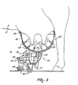
- Figure 3 is a schematic view of a cleaning and/or drying unit for the udder, which can be coupled automatically to the udder of the animal;
- Figure 4 is a schematic view of a milking unit which can be coupled automatically to the udder of the animal;
- Figure 5 shows schematically a side view along the line V - V of Figure 4;
- Figure 6 shows schematically an installed device for milking animals; and
- Figure 7 shows schematically a service vehicle for the device of Figure 6.
-
- Corresponding components in the several figures are given the same reference numerals.
- Figure 1 shows a device including a box 1 (milking parlour) for the
animal 2, this box 1 having adoor 3 through which theanimal 2 can enter the box and adoor 4 through which the animal can leave the box 1. Bothdoors guide rods 5 which are connected hingeably to the frame of the device by means of theirends 6 and whose other ends 7 are connected capable of hinging to thesupports 8 provided on the door. Figure 1 shows the twodoors doors manger 9 is attached to thedoor 4 from which theanimal 2 can eat concentrate or another kind of fodder during its stay in the box 1. Because, on opening of thedoor 4, also themanger 9 is removed, the animal will tend to leave the box 1 earlier than otherwise. - Three
storage containers animal 2.Storage container 10 is intended for fodder, for example concentrate, the animal can eat during its stay in the box 1. Thestorage container 10 has a fill opening 13 and a metering discharge outlet 14, which in answer to a control signal, feeds a predetermined quantity of fodder to themanger 9. Thestorage container 10 may be of such a construction that, as shown in Figure 1, the fodder can flow to the manger without any additional conveyor means. - Storage container 11 is intended for storing milk and for that purpose, can comprise means for cooling the milk stored in the container.
Storage container 12 is intended to store a cleaning fluid, for example water, which can be used for cleaning, disinfecting and rinsing parts coming into contact with the milk, such as milk pipes, the milking cluster, the udder, or further parts eligible for cleaning or rinsing. - Figure 1 also shows a
unit 15 which can be coupled to the udder of theanimal 2.Unit 15 includes a bowl 16 which is in an almost close contact around the cow's udder and is supported in the centre by asupport 17 which is attached to the floor and will be further described in the sequel with reference to Figure 3. - In addition, there is a
device 18 for conveying milk to the storage tank 11. Device 19 has for its object to heat air and to convey that heated air to the udder-couplable device 15, as will be described in greater detail hereinafter. Usingdevice 20, the detergent can be pumped from thestorage container 12 to the udder-couplable arrangement 15. Theconveyor conduits 21 required for this purpose are shown schematically. - A
collar 22 is provided around the animal's neck, to which means 23 for identifying the animal are fastened. These means 23 may be constituted by an electronic or magnetic information carrier or a transmitter transmitting a signal which is specific to the givenanimal 2. Additonally, the device includes acomputer 24 which controls the several functions of the device. For that purpose thecomputer 24 is connected to different portions of the device, which is illustrated in Figure 1 by means of lines. - The device further includes a
loudspeaker 25 for producing sound or music so as to pass the desired signals on to the animal. - Figure 2 shows schematically three adjacent milking parlours or boxes 1, which are separated from each other by
partitions 26. Furthermore guide means 27, constituted by, for example, rods are provided with the object of giving the animal only a limited freedom of movement. Figure 2 shows two types of devices couplable to the udder of the animal, namely a cleaning and/ordrying unit 28 and amilking unit 29. Theseunits unit 28 can be moved to under the animal from one side, whilstunit 29 can be moved to under the animal from the other side. Both units have a support including two substantiallyvertical hinge pins hinge pin 30 being fastened to the floor, so that theunit units -
Unit 28 includes a bowl 16 (Figure 3) which is substantially in close contact around the animal's udder and has a plurality of sprayingnozzles 32 for spraying a cleaning liquid against the animals udder, and acentral aperture 33 for discharging used-up cleaning liquid and also for supplying air, which optionally may have been heated, with the object of drying the udder after cleaning. -
Unit 29 includes amilking cluster 34 which is connectable to the teats of the udder and ashield 35, as will be explained in greater detail in the sequel. - The
storage containers - The described device for milking animals may be in the form of a mobile unit or built in a movable container which can in its totality be positioned in a desired location. Optionally the device may be provided, for this purpose, with wheels 36 (Figure 2), or other means useful for moving the implement. So as to enable positioning of the device in the open air, it may be provided with a
roof 37 extending along the overall device (Figure 1). - Figure 3 shows in greater detail the
unit 28 already shown in Figure 2. Theunit 28 includes a bowl 16 which can be moved to under the animal and around its udder by means ofsupport 17.Support 17 is capable of swivelling aroundhinge pin 30, the support being fastened to the floor in the region of this hinge pin. The support includes a firstelectric motor 38 for moving thedevice 38 upwards, for example by means of a spindle arranged concentrically to pin 30. Additionally, a secondelectric motor 39 is provided, so that swivelling aroundpin 30 of the support can be effected. The support furthermore comprises a second, substantiallyvertical hinge pin 31 whereby connecting members 40 and 41 of the support are capable of swivelling relative to each other. At its end, the connecting member 41 bears the bowl 16, which is provided withspray nozzles 32 and acentral aperture 33. Theaperture 33 provided centrally in the bowl 16 is made in the spot where the connecting member 41 is connected to the bowl 16. - A liquid, for example warm water, can be applied to the
spray nozzles 32 through conduit 42 by means of device 20 (Figure 1). The used-up liquid can be discharged throughoutlet 33 andconduit 43 to any place outside the milking device. So as to enable drying of the udders after cleaning, device 19 (Figure 1) can optionally apply warm air through conduit 44, which air is also passed to the udder throughaperture 33. - So as to ensure that the air applied through conduit 44 and the liquid discharged through
conduit 43 can not mutually affect each other, a non-return valve 45 is provided in the embodiment shown in Figure 3 in conduit 44, which valve passes the air current supplied, but constitutes a shut-off means for any liquid from the other direction. Additionally,conduit 43 is provided with an S-curve, so that a liquid lock is formed, to ensure that the air supplied through conduit 44 cannot flow away throughconduit 43. - The milking device as shown in Figure 3 is computer-controlled, such that the bowl 16 first assumes an appropriate position in a substantially horizontal plane, whereafter the bowl is moved up, so that it is in a position around the udder of the animal. So as to facilitate this procedure, the edge of the bowl is provided with a strip 46 of a flexible material. The
conduits 42, 43 and 44 must be adequately flexible to follow the motions of the bowl 16. As has already been described in the foregoing, moving the bowl is effected by a firstelectric motor 38, which can adjust the unit in the vertical direction, a secondelectric motor 39 being present for rotation around thepin 30 and a third electric motor being present for the mutual rotation of the connecting members 40 and 41 around thepin 31. To that end, the computer is connected to each one of said motors by means ofelectric connections 48. - Figure 4 shows the unit 29 (see Figure 2). The unit comprises a milking cluster having four
teat cups 52. These teat cups 52 may be of a conventional structure, but they may alternatively be of somewhat more flaring construction to facilitate connection to the teats. The support shown in Figure 4 is of the same type as shown in, and described with reference to, Figure 3. Using the computer-controlledelectric motors - At one side of the milking cluster the arrangement shown in Figure 4 is provided with a
plate 35 having a foldededge 51 at its top. Theplate 35 has for its object to provide a shield between the hind legs of the animal and the milking cluster, more specifically for preventing the milking cluster from being contaminated. - Figure 5 shows a side view along the line V-V of Figure 4, in which further details of the milking cluster are shown. In accordance with Figure 5, each
teat cup 52 is connected, capably of hinging, to a central support 54, so that relative to the central support 54, eachteat cup 52 is movable in a certain area. By means of smallelectric motors teat cups 52, which together form the milking cluster, are arranged in a configuration which is adapted to the relevant animal. - Figure 6 shows schematically a mobile milking device comprising three milking parlours and being located in, for example, a meadow, so that
animals 2, for example cows, walk around the implement. - Figure 7 shows a trailer placed behind a tractor, which trailer is provided with
different storage containers - Using the tractor and trailer combination shown in Figure 7, a trip can be made to the milking device of Figure 6, with the object of collecting milk and of bringing fodder and liquid.
- Although the device for milking animals can also be incorporated in any type of stable, the following description is based on a situation in which the milking device is installed in a meadow, as shown in Figure 6.
- The animals walk freely around the automatic milking device. The object in mind is that all the animals make a more or less regular appearance in a milking parlour of the milking device, to be milked there. For that purpose the animals can be lured to the milking parlour by the presence of concentrate, it is however alternatively possible to call the animals by means of sound signals. To that end, each animal has a collar with a receiver attached thereto, which is connected to a loudspeaker located in the region of the animal's ears. In the milking device is a computer-controlled, transmitter, so that the computer can convey a call signal through the loudspeaker of the relevant cow. Thus, each desired animal can be invited to go to the milking parlour by means of, for example, agreeable sounds, as the animal then knows that there is, for example, concentrate available. Simultaneously, the animals whose presence in the neighbourhood of the milking parlour is undesired, may be given an unpleasant signal as soon as they are too close near the milking parlour. Instead of radio signals, it is alternatively possible to use sound signals generated by means of a loudspeaker, denoted by 61 in Figure 1. Since also identifying means are fastened to the collar of the cow, for example a transmitter transmitting given signals, sensor means of the milking device will sense the presence of a certain animal, after door 3 (Figure 1) has been opened by the computer so as to allow admittance to the milking parlour for the relevant animal. Depending on that specific animal, the computer supplies a predetermined, metered quantity of concentrate to the manger and a device for cleaning the udders is coupled to the udders. Because the animal eats the fodder supplied, it is in a given position and the computer can control the units to be coupled to the udder in such a manner that they are coupled in the appropriate way. A drying operation can follow after a cleaning operation, whereafter the device coupled to the udder moves back to its starting position and the milking cluster can be moved to under the animal from the other side and be coupled to the udder, also controlled by the computer, the mutual positions of the teat cups having been adapted to the udder of the specific animal. After the milking cycle has been terminated, the milking cluster returns to its starting position, whereafter
door 4 is opened and both the door and the manger are moved, so that the animal can leave the milking parlour. To enable correct coupling of the relevant unit to the udder, the computer has the disposition of the relevant data of each animal, on the basis of which data theunits - In connection with an optimal milk production it is of utmost importance that the animal feels comfortable in all situations or is even positively influenced. This influencing can be done by means of sounds produced by a
loudspeaker 25 provided in the milking parlour wall (Figure 1). This loudspeaker can be used in the first place for luring the animal, by producing a sound pleasant to the animal, for example a certain type of music. During milking, this music can be varied such that it promotes the milk production, for example by starting slowly and gradually passing into a more dynamic form. Thesame loudspeaker 25 can be used to encourage the animal to leave the milking parlour, by, for example, producing unpleasant sounds, for example shrill sounds. - It will be clear that the animal can also be lured to the milking parlour in any other suitable way. It may also be advantageous to have the animal decide itself whether it wants to be milked, for which purpose the sensor means detect the presence of the relative animal, whereafter that animal is permitted to enter the milking parlour. Thus, it is possible to raise milking to very many times per day, depending on the own needs of the animal, which may be advantageous for the milk production.
- It is of course alternatively possible to incorporate the milking arrangement in an open stable or in any other type of stable.
Claims (6)
- A device for milking animals, such as cows, comprising a milking parlour (1) with an entry door (3), an exit door (4) and lateral guide means (27) giving the animal only a limited freedom of movement and bounding the area of the milking parlour where the animal stands during the milking process and with a manger (9) attached to the exit door (4) of the milking parlour from which the animal can eat fodder during its stay in the milking parlour so that the animal then is in a given position in the milking parlour, the device comprising a computer-controlled milking machine with a milking cluster (34) couplable to the udder of the animal and with a unit (28) suitable for either spraying a liquid or for spraying a liquid and drying comprising a bowl-shaped basin (16) connectable to the udder of the animal and provided with spraying means (32) for spraying said liquid against the animal's udder and teats, said liquid being a cleaning, rinsing or disinfecting agent, the milking cluster (34) being supported on a milking cluster support (17, 40, 41) and the unit (28) suitable for either spraying a liquid or for spraying a liquid and drying being supported on a cleaning/drying unit support (17, 40, 41), said milking cluster support (17, 40, 41) permitting an upwardly and downwardly movement of the milking cluster (34), said cleaning/drying unit support (17, 40, 41) permitting an upwardly and downwardly movement of the unit (28) suitable for either spraying a liquid or for spraying a liquid and drying, the milking cluster (34) being located in its non-operative position on one side of said area and outside said area such that it is adjacent to the udder of the animal when the animal is in the milking parlour, the milking cluster support (17, 40, 41) and the cleaning/drying unit support (17, 40, 41) each comprising a first vertical hinge pin (30) and being fastened to the floor of the milking parlour in the region of the first hinge pin (30), each support (17) comprising a first connecting member (40) swivelling around the first vertical hinge pin (30), a second vertical hinge pin and a second connecting member (41) connected to the first connecting member (40) by the second vertical hinge pin (31), the milking cluster (34) and the bowl-shaped basin of the unit (28) suitable for either spraying a liquid or for spraying a liquid and drying being supported on the respective second connecting member (41) of the support (17), the first vertical hinge pin (30) permitting a swivelling movement of the support (17) and the second vertical hinge pin (31) permitting a swivelling movement of the connecting members (40, 41) relative to each other so that the resulting movements of the milking cluster (34) and the unit (28) suitable for either spraying a liquid or for spraying a liquid and drying are caused in such a way that they approach the udder of the animal from the respective side of the milking parlour between a foreleg and a hindleg of the animal and then move backwards to the udder, the unit (28) suitable for either spraying a liquid or for spraying a liquid and drying being couplable to the udder of the animal, the unit (28) suitable for either spraying a liquid or for spraying a liquid and drying being located in its non-operative position on the other side of said area and outside said area such that it is adjacent to the udder of the animal when the animal is in the milking parlour.
- A device as claimed in claim 1, characterized in that the spraying means (32) are directed upwardly.
- A device as claimed in claim 1 or 2, characterized in that the bowl-shaped basin (16) is supported near its centre by the support (17) and comprises a discharge pipe (43) located in the support (17).
- A device as claimed in claim 3, characterized in that the bowl-shaped basin (16) comprises an air pipe (44) through which an air flow can be passed, the exit end of the air pipe (44) being directed towards the animal's teats.
- A device as claimed in claim 4, characterized in that the air pipe (44) constitutes the discharge pipe (43).
- A device as claimed in any one of the preceding claims, characterized in that the movement of the unit (28) is effected by computer-controlled electric motors (38, 39, 47).
Priority Applications (4)
| Application Number | Priority Date | Filing Date | Title |
|---|---|---|---|
| EP94202761A EP0630566B1 (en) | 1985-01-16 | 1986-01-15 | A device for automatically milking animals |
| EP94202067A EP0630561B2 (en) | 1985-01-16 | 1986-01-15 | A device for automatically milking animals |
| EP94202066A EP0630560A1 (en) | 1985-01-16 | 1986-01-15 | A device for automatically milking animals |
| EP94202065A EP0630559A1 (en) | 1985-01-16 | 1986-01-15 | A device for automatically milking animals |
Applications Claiming Priority (7)
| Application Number | Priority Date | Filing Date | Title |
|---|---|---|---|
| NL8500089 | 1985-01-16 | ||
| NL8500091A NL8500091A (en) | 1985-01-16 | 1985-01-16 | Implement for milking cows - includes milking machine and signal generator to control movement of cows |
| NL8500089A NL192241C (en) | 1985-01-16 | 1985-01-16 | Device for milking animals, such as cows. |
| NL8500091 | 1985-01-16 | ||
| NL8500090A NL192812C (en) | 1985-01-16 | 1985-01-16 | Method for milking animals, such as cows, at a milking parlor from a free-flowing herd. |
| NL8500090 | 1985-01-16 | ||
| EP86200064A EP0189954B1 (en) | 1985-01-16 | 1986-01-15 | Implement and method for milking animals, such as cows |
Related Parent Applications (2)
| Application Number | Title | Priority Date | Filing Date |
|---|---|---|---|
| EP86200064A Division EP0189954B1 (en) | 1985-01-16 | 1986-01-15 | Implement and method for milking animals, such as cows |
| EP86200064.3 Division | 1986-01-15 |
Related Child Applications (7)
| Application Number | Title | Priority Date | Filing Date |
|---|---|---|---|
| EP94202067A Division EP0630561B2 (en) | 1985-01-16 | 1986-01-15 | A device for automatically milking animals |
| EP94202065A Division EP0630559A1 (en) | 1985-01-16 | 1986-01-15 | A device for automatically milking animals |
| EP94202065.2 Division-Into | 1986-01-15 | ||
| EP94202761.6 Division-Into | 1986-01-15 | ||
| EP94202067.8 Division-Into | 1986-01-15 | ||
| EP94202761A Division EP0630566B1 (en) | 1985-01-16 | 1986-01-15 | A device for automatically milking animals |
| EP94202066.0 Division-Into | 1986-01-15 |
Publications (4)
| Publication Number | Publication Date |
|---|---|
| EP0332231A2 EP0332231A2 (en) | 1989-09-13 |
| EP0332231A3 EP0332231A3 (en) | 1989-10-11 |
| EP0332231B1 EP0332231B1 (en) | 1995-04-12 |
| EP0332231B2 true EP0332231B2 (en) | 2002-06-12 |
Family
ID=27441016
Family Applications (4)
| Application Number | Title | Priority Date | Filing Date |
|---|---|---|---|
| EP89107974A Expired - Lifetime EP0332229B2 (en) | 1985-01-16 | 1986-01-15 | Device for milking animals, such as cows |
| EP89107976A Expired - Lifetime EP0332231B2 (en) | 1985-01-16 | 1986-01-15 | Device for milking animals, such as cows |
| EP89107977A Expired - Lifetime EP0332232B2 (en) | 1985-01-16 | 1986-01-15 | Device for milking animals, such as cows |
| EP89107975A Expired - Lifetime EP0332230B2 (en) | 1985-01-16 | 1986-01-15 | Device for milking animals, such as cows |
Family Applications Before (1)
| Application Number | Title | Priority Date | Filing Date |
|---|---|---|---|
| EP89107974A Expired - Lifetime EP0332229B2 (en) | 1985-01-16 | 1986-01-15 | Device for milking animals, such as cows |
Family Applications After (2)
| Application Number | Title | Priority Date | Filing Date |
|---|---|---|---|
| EP89107977A Expired - Lifetime EP0332232B2 (en) | 1985-01-16 | 1986-01-15 | Device for milking animals, such as cows |
| EP89107975A Expired - Lifetime EP0332230B2 (en) | 1985-01-16 | 1986-01-15 | Device for milking animals, such as cows |
Country Status (2)
| Country | Link |
|---|---|
| EP (4) | EP0332229B2 (en) |
| AT (1) | ATE74254T1 (en) |
Families Citing this family (33)
| Publication number | Priority date | Publication date | Assignee | Title |
|---|---|---|---|---|
| NL9002047A (en) * | 1990-09-18 | 1992-04-16 | Lely Nv C Van Der | CLEANING INSTALLATION. |
| GB9113405D0 (en) * | 1991-06-20 | 1991-08-07 | Silsoe Research Inst | Automatic milking |
| NL9200258A (en) * | 1991-10-04 | 1993-05-03 | Lely Nv C Van Der | METHOD FOR CLEANING MILK BEAKERS AND / OR AFTER-TREATMENT OF THE WEANING OF A MILKED ANIMAL, ANIMAL MILKING APPARATUS FOR USING THIS METHOD (S), AND A RINSE TOOL APPLIED IN SUCH AN APPARATUS. |
| NL9101673A (en) * | 1991-10-04 | 1993-05-03 | Texas Industries Inc | Apparatus for cleaning teats of milking animals. |
| DK0543463T3 (en) * | 1991-11-22 | 2001-07-16 | Berthold Johannes The Dietrich | Device for pneumatic milking and teat cups for such device |
| NL9200091A (en) * | 1992-01-17 | 1993-08-16 | Lely Nv C Van Der | MILK MACHINE. |
| NL9200639A (en) * | 1992-04-06 | 1993-11-01 | Lely Nv C Van Der | DEVICE FOR AUTOMATIC MILKING OF ANIMALS. |
| NL9200714A (en) * | 1992-04-21 | 1993-11-16 | Lely Nv C Van Der | DEVICE FOR AUTOMATIC MILKING OF ANIMALS. |
| NL9200924A (en) * | 1992-05-26 | 1993-12-16 | Lely Nv C Van Der | DEVICE FOR AUTOMATIC MILKING OF ANIMALS. |
| NL9300242A (en) * | 1993-02-08 | 1994-09-01 | Lely Nv C Van Der | Device for milking animals. |
| NL9300579A (en) * | 1993-04-01 | 1994-11-01 | Lely Nv C Van Der | Device for milking animals, such as cows. |
| NL9301098A (en) * | 1993-06-24 | 1995-01-16 | Texas Industries Inc | Device for automatic milking of animals. |
| NL9301214A (en) † | 1993-07-12 | 1995-02-01 | Texas Industries Inc | Device for automatic milking of animals. |
| NL9301317A (en) * | 1993-07-28 | 1995-02-16 | Lely Nv C Van Der | Device for automatic milking of animals. |
| NL9301377A (en) * | 1993-08-09 | 1995-03-01 | Lely Nv C Van Der | Device for automatic milking of animals. |
| NL9500362A (en) * | 1994-04-14 | 1995-11-01 | Maasland Nv | Method for automatic milking of animals and device in which this method can be applied. |
| NL9401033A (en) * | 1994-06-23 | 1996-02-01 | Maasland Nv | Construction with a device for automatic milking of animals. |
| NL9401801A (en) * | 1994-08-23 | 1996-04-01 | Maasland Nv | Construction with a device for milking animals. |
| NL9401802A (en) * | 1994-10-31 | 1996-06-03 | Maasland Nv | Device for milking animals. |
| DE69523628T2 (en) † | 1994-12-28 | 2002-05-16 | Delaval Holding Ab | DEVICE AND METHOD FOR MANAGING ANIMALS |
| SE9503588D0 (en) * | 1995-10-13 | 1995-10-13 | Tetra Laval Holdings & Finance | A method of milking and a milking apparatus |
| SE9603840D0 (en) * | 1996-10-18 | 1996-10-18 | Tetra Laval Holdings & Finance | An apparatus for a method of monitoring animal space |
| SE513749C2 (en) * | 1999-01-15 | 2000-10-30 | Alfa Laval Agri Ab | Method and apparatus for positioning teat cups on a dairy animal |
| SE517531C2 (en) * | 1999-05-06 | 2002-06-18 | Alfa Laval Agri Ab | Device and method for cleaning teats |
| SE517141C2 (en) * | 2000-06-07 | 2002-04-23 | Delaval Holding Ab | Procedure for milking where the animals are ranked as well as milking parlors and computer software for this |
| NL1015670C2 (en) * | 2000-07-10 | 2002-01-11 | Lely Entpr Ag | Device for automatic milking of animals. |
| SE520347C2 (en) | 2001-10-08 | 2003-07-01 | Delaval Holding Ab | Procedure for handling animals and milking station respectively |
| DE10208932C1 (en) | 2002-02-28 | 2003-07-10 | Westfalia Landtechnik Gmbh | Animal tracking or imprinting for e.g. milking cows includes determining animal coordinates at two or more time points and carrying out aversion treatment if a difference between the coordinates lies outside a preset range |
| US8152751B2 (en) | 2007-02-09 | 2012-04-10 | Baxter International Inc. | Acoustic access disconnection systems and methods |
| NL2013390B1 (en) | 2014-08-29 | 2016-09-26 | Lely Patent Nv | System and method for managing dairy animals. |
| DE102016121676A1 (en) | 2016-11-11 | 2018-05-30 | Duräumat-Agrotec Agrartechnik GmbH | Eater sprayer for a milking parlor |
| DE202016106333U1 (en) | 2016-11-11 | 2016-11-22 | Duräumat-Agrotec Agrartechnik GmbH | Eater sprayer for a milking parlor |
| CN110050701A (en) * | 2019-05-09 | 2019-07-26 | 上海康臣生物科技有限公司 | A kind of milk cow nipple washing and brushing device and brushing method |
Family Cites Families (10)
| Publication number | Priority date | Publication date | Assignee | Title |
|---|---|---|---|---|
| DD74974A (en) † | ||||
| DE894931C (en) * | 1951-09-15 | 1953-10-29 | Hans Ehlers | Auxiliary device for mechanical pasture milking |
| GB918766A (en) * | 1959-02-03 | 1963-02-20 | Edward David Dyke | Milking equipment |
| US3019763A (en) * | 1960-01-14 | 1962-02-06 | Starline | Mobile milking house and milk room |
| GB1221302A (en) * | 1967-08-15 | 1971-02-03 | Frederick George Brown | Improvements in bails for cows and other cattle |
| DE1900502A1 (en) * | 1969-01-07 | 1970-08-06 | S P R L Les Ateliers N Bottin | Mobile animal shed |
| US4010714A (en) * | 1974-03-08 | 1977-03-08 | Director, National Institute Of Animal Industry | System for managing milking-cows in stanchion stool |
| GB2007486B (en) * | 1977-11-12 | 1982-03-03 | Akerman D E | Milking method and apparatus |
| IL64596A0 (en) † | 1980-12-29 | 1982-03-31 | Unihold Trading Int | Milking machine |
| SE430559B (en) * | 1982-04-08 | 1983-11-28 | Alfa Laval Ab | SET FOR MILK AND DEVICE HERE |
-
1986
- 1986-01-15 AT AT86200064T patent/ATE74254T1/en not_active IP Right Cessation
- 1986-01-15 EP EP89107974A patent/EP0332229B2/en not_active Expired - Lifetime
- 1986-01-15 EP EP89107976A patent/EP0332231B2/en not_active Expired - Lifetime
- 1986-01-15 EP EP89107977A patent/EP0332232B2/en not_active Expired - Lifetime
- 1986-01-15 EP EP89107975A patent/EP0332230B2/en not_active Expired - Lifetime
Also Published As
| Publication number | Publication date |
|---|---|
| EP0332230B1 (en) | 1995-09-27 |
| EP0332232A2 (en) | 1989-09-13 |
| EP0332231A3 (en) | 1989-10-11 |
| EP0332229B1 (en) | 1995-09-20 |
| ATE74254T1 (en) | 1992-04-15 |
| EP0332229A2 (en) | 1989-09-13 |
| EP0332230A3 (en) | 1991-11-06 |
| EP0332232A3 (en) | 1989-10-04 |
| EP0332229A3 (en) | 1991-11-06 |
| EP0332231B1 (en) | 1995-04-12 |
| EP0332230A2 (en) | 1989-09-13 |
| EP0332231A2 (en) | 1989-09-13 |
| EP0332232B1 (en) | 1993-12-29 |
| EP0332229B2 (en) | 2001-08-22 |
| EP0332230B2 (en) | 2002-01-09 |
| EP0332232B2 (en) | 1998-12-02 |
Similar Documents
| Publication | Publication Date | Title |
|---|---|---|
| EP0332231B2 (en) | Device for milking animals, such as cows | |
| EP0630561B1 (en) | A device for automatically milking animals | |
| US5195455A (en) | Arrangement for keeping dairy animals clean | |
| US5865138A (en) | Method and apparatus for automatically milking animals, such as cows | |
| EP0541517B1 (en) | A device for milking animals | |
| EP0630558B2 (en) | A construction for automatically milking animals | |
| EP0319523B1 (en) | Device for automatically milking an animal | |
| EP0323444B1 (en) | A device for milking animals, such as cows | |
| US20020124802A1 (en) | Construction for automatically milking animals | |
| NL8900416A (en) | DEVICE FOR CLEANING DAIRY ANIMALS. | |
| WO1998026649A1 (en) | A construction including an implement for automatically milking animals | |
| NL192812C (en) | Method for milking animals, such as cows, at a milking parlor from a free-flowing herd. | |
| NL8500091A (en) | Implement for milking cows - includes milking machine and signal generator to control movement of cows | |
| NL8500089A (en) | Implement for milking cows - includes milking machine and signal generator to control movement of cows | |
| JPH1189461A (en) | Milking method and equipment | |
| JPH1189466A (en) | Milking equipment | |
| JPH1189465A (en) | Milking equipment |
Legal Events
| Date | Code | Title | Description |
|---|---|---|---|
| PUAI | Public reference made under article 153(3) epc to a published international application that has entered the european phase |
Free format text: ORIGINAL CODE: 0009012 |
|
| PUAL | Search report despatched |
Free format text: ORIGINAL CODE: 0009013 |
|
| AC | Divisional application: reference to earlier application |
Ref document number: 189954 Country of ref document: EP |
|
| AK | Designated contracting states |
Kind code of ref document: A2 Designated state(s): AT BE CH DE FR GB IT LI NL SE |
|
| AK | Designated contracting states |
Kind code of ref document: A3 Designated state(s): AT BE CH DE FR GB IT LI NL SE |
|
| 17P | Request for examination filed |
Effective date: 19900314 |
|
| 17Q | First examination report despatched |
Effective date: 19910208 |
|
| GRAA | (expected) grant |
Free format text: ORIGINAL CODE: 0009210 |
|
| AC | Divisional application: reference to earlier application |
Ref document number: 189954 Country of ref document: EP |
|
| AK | Designated contracting states |
Kind code of ref document: B1 Designated state(s): AT BE CH DE FR GB IT LI NL SE |
|
| REF | Corresponds to: |
Ref document number: 120928 Country of ref document: AT Date of ref document: 19950415 Kind code of ref document: T |
|
| XX | Miscellaneous (additional remarks) |
Free format text: TEILANMELDUNG 94202065.2 EINGEREICHT AM 15/01/86. |
|
| REF | Corresponds to: |
Ref document number: 3650298 Country of ref document: DE Date of ref document: 19950518 |
|
| K2C2 | Correction of patent specification (partial reprint) published |
Effective date: 19950412 |
|
| ITF | It: translation for a ep patent filed |
Owner name: STUDIO ING. ALFREDO RAIMONDI |
|
| ET | Fr: translation filed | ||
| PLBQ | Unpublished change to opponent data |
Free format text: ORIGINAL CODE: EPIDOS OPPO |
|
| PLBI | Opposition filed |
Free format text: ORIGINAL CODE: 0009260 |
|
| PLBI | Opposition filed |
Free format text: ORIGINAL CODE: 0009260 |
|
| PLBQ | Unpublished change to opponent data |
Free format text: ORIGINAL CODE: EPIDOS OPPO |
|
| PLAV | Examination of admissibility of opposition |
Free format text: ORIGINAL CODE: EPIDOS OPEX |
|
| PLAV | Examination of admissibility of opposition |
Free format text: ORIGINAL CODE: EPIDOS OPEX |
|
| PLBF | Reply of patent proprietor to notice(s) of opposition |
Free format text: ORIGINAL CODE: EPIDOS OBSO |
|
| 26 | Opposition filed |
Opponent name: ALFA LAVAL AGRI AB Effective date: 19960110 |
|
| 26 | Opposition filed |
Opponent name: PROLION B.V. Effective date: 19960112 Opponent name: ALFA LAVAL AGRI AB Effective date: 19960110 |
|
| NLR1 | Nl: opposition has been filed with the epo |
Opponent name: PROLION B.V. Opponent name: ALFA LAVAL AGRI AB |
|
| PLBF | Reply of patent proprietor to notice(s) of opposition |
Free format text: ORIGINAL CODE: EPIDOS OBSO |
|
| PLBF | Reply of patent proprietor to notice(s) of opposition |
Free format text: ORIGINAL CODE: EPIDOS OBSO |
|
| RAP2 | Party data changed (patent owner data changed or rights of a patent transferred) |
Owner name: MAASLAND N.V. |
|
| NLT2 | Nl: modifications (of names), taken from the european patent patent bulletin |
Owner name: MAASLAND N.V. |
|
| NLS | Nl: assignments of ep-patents |
Owner name: MAASLAND N.V. |
|
| REG | Reference to a national code |
Ref country code: CH Ref legal event code: PUE Owner name: C. VAN DER LELY N.V. TRANSFER- MAASLAND N.V. |
|
| PLAW | Interlocutory decision in opposition |
Free format text: ORIGINAL CODE: EPIDOS IDOP |
|
| APAC | Appeal dossier modified |
Free format text: ORIGINAL CODE: EPIDOS NOAPO |
|
| APAE | Appeal reference modified |
Free format text: ORIGINAL CODE: EPIDOS REFNO |
|
| APAC | Appeal dossier modified |
Free format text: ORIGINAL CODE: EPIDOS NOAPO |
|
| PLBQ | Unpublished change to opponent data |
Free format text: ORIGINAL CODE: EPIDOS OPPO |
|
| PLAB | Opposition data, opponent's data or that of the opponent's representative modified |
Free format text: ORIGINAL CODE: 0009299OPPO |
|
| R26 | Opposition filed (corrected) |
Opponent name: ALFA LAVAL AGRI AB * 19960112 PROLION B.V. Effective date: 19960110 |
|
| NLR1 | Nl: opposition has been filed with the epo |
Opponent name: PROLION B.V. Opponent name: ALFA LAVAL AGRI AB |
|
| APAC | Appeal dossier modified |
Free format text: ORIGINAL CODE: EPIDOS NOAPO |
|
| REG | Reference to a national code |
Ref country code: GB Ref legal event code: IF02 |
|
| PLAW | Interlocutory decision in opposition |
Free format text: ORIGINAL CODE: EPIDOS IDOP |
|
| PUAH | Patent maintained in amended form |
Free format text: ORIGINAL CODE: 0009272 |
|
| STAA | Information on the status of an ep patent application or granted ep patent |
Free format text: STATUS: PATENT MAINTAINED AS AMENDED |
|
| 27A | Patent maintained in amended form |
Effective date: 20020612 |
|
| AK | Designated contracting states |
Kind code of ref document: B2 Designated state(s): AT BE CH DE FR GB IT LI NL SE |
|
| XX | Miscellaneous (additional remarks) |
Free format text: TEILANMELDUNG 94202065.2 EINGEREICHT AM 15/01/86. |
|
| REG | Reference to a national code |
Ref country code: CH Ref legal event code: AEN Free format text: AUFRECHTERHALTUNG DES PATENTES IN GEAENDERTER FORM |
|
| NLR2 | Nl: decision of opposition | ||
| ET3 | Fr: translation filed ** decision concerning opposition | ||
| NLR3 | Nl: receipt of modified translations in the netherlands language after an opposition procedure | ||
| PGFP | Annual fee paid to national office [announced via postgrant information from national office to epo] |
Ref country code: FR Payment date: 20021218 Year of fee payment: 18 |
|
| PGFP | Annual fee paid to national office [announced via postgrant information from national office to epo] |
Ref country code: SE Payment date: 20021219 Year of fee payment: 18 Ref country code: AT Payment date: 20021219 Year of fee payment: 18 |
|
| PGFP | Annual fee paid to national office [announced via postgrant information from national office to epo] |
Ref country code: NL Payment date: 20021223 Year of fee payment: 18 Ref country code: CH Payment date: 20021223 Year of fee payment: 18 |
|
| PGFP | Annual fee paid to national office [announced via postgrant information from national office to epo] |
Ref country code: GB Payment date: 20030108 Year of fee payment: 18 |
|
| PGFP | Annual fee paid to national office [announced via postgrant information from national office to epo] |
Ref country code: BE Payment date: 20030114 Year of fee payment: 18 |
|
| PGFP | Annual fee paid to national office [announced via postgrant information from national office to epo] |
Ref country code: DE Payment date: 20030131 Year of fee payment: 18 |
|
| PG25 | Lapsed in a contracting state [announced via postgrant information from national office to epo] |
Ref country code: GB Free format text: LAPSE BECAUSE OF NON-PAYMENT OF DUE FEES Effective date: 20040115 Ref country code: AT Free format text: LAPSE BECAUSE OF NON-PAYMENT OF DUE FEES Effective date: 20040115 |
|
| PG25 | Lapsed in a contracting state [announced via postgrant information from national office to epo] |
Ref country code: SE Free format text: LAPSE BECAUSE OF NON-PAYMENT OF DUE FEES Effective date: 20040116 |
|
| PG25 | Lapsed in a contracting state [announced via postgrant information from national office to epo] |
Ref country code: LI Free format text: LAPSE BECAUSE OF NON-PAYMENT OF DUE FEES Effective date: 20040131 Ref country code: CH Free format text: LAPSE BECAUSE OF NON-PAYMENT OF DUE FEES Effective date: 20040131 Ref country code: BE Free format text: LAPSE BECAUSE OF NON-PAYMENT OF DUE FEES Effective date: 20040131 |
|
| BERE | Be: lapsed |
Owner name: *MAASLAND N.V. Effective date: 20040131 |
|
| PG25 | Lapsed in a contracting state [announced via postgrant information from national office to epo] |
Ref country code: NL Free format text: LAPSE BECAUSE OF NON-PAYMENT OF DUE FEES Effective date: 20040801 |
|
| PG25 | Lapsed in a contracting state [announced via postgrant information from national office to epo] |
Ref country code: DE Free format text: LAPSE BECAUSE OF NON-PAYMENT OF DUE FEES Effective date: 20040803 |
|
| EUG | Se: european patent has lapsed | ||
| GBPC | Gb: european patent ceased through non-payment of renewal fee |
Effective date: 20040115 |
|
| REG | Reference to a national code |
Ref country code: CH Ref legal event code: PL |
|
| PG25 | Lapsed in a contracting state [announced via postgrant information from national office to epo] |
Ref country code: FR Free format text: LAPSE BECAUSE OF NON-PAYMENT OF DUE FEES Effective date: 20040930 |
|
| NLV4 | Nl: lapsed or anulled due to non-payment of the annual fee |
Effective date: 20040801 |
|
| REG | Reference to a national code |
Ref country code: FR Ref legal event code: ST |
|
| PG25 | Lapsed in a contracting state [announced via postgrant information from national office to epo] |
Ref country code: IT Free format text: LAPSE BECAUSE OF NON-PAYMENT OF DUE FEES Effective date: 20050115 |
|
| APAH | Appeal reference modified |
Free format text: ORIGINAL CODE: EPIDOSCREFNO |