EP0189954B1 - Implement and method for milking animals, such as cows - Google Patents
Implement and method for milking animals, such as cows Download PDFInfo
- Publication number
- EP0189954B1 EP0189954B1 EP86200064A EP86200064A EP0189954B1 EP 0189954 B1 EP0189954 B1 EP 0189954B1 EP 86200064 A EP86200064 A EP 86200064A EP 86200064 A EP86200064 A EP 86200064A EP 0189954 B1 EP0189954 B1 EP 0189954B1
- Authority
- EP
- European Patent Office
- Prior art keywords
- milking
- animal
- parlour
- animals
- milking parlour
- Prior art date
- Legal status (The legal status is an assumption and is not a legal conclusion. Google has not performed a legal analysis and makes no representation as to the accuracy of the status listed.)
- Expired - Lifetime
Links
Images


Classifications
-
- A—HUMAN NECESSITIES
- A01—AGRICULTURE; FORESTRY; ANIMAL HUSBANDRY; HUNTING; TRAPPING; FISHING
- A01J—MANUFACTURE OF DAIRY PRODUCTS
- A01J5/00—Milking machines or devices
- A01J5/017—Automatic attaching or detaching of clusters
- A01J5/0175—Attaching of clusters
-
- A—HUMAN NECESSITIES
- A01—AGRICULTURE; FORESTRY; ANIMAL HUSBANDRY; HUNTING; TRAPPING; FISHING
- A01J—MANUFACTURE OF DAIRY PRODUCTS
- A01J7/00—Accessories for milking machines or devices
- A01J7/04—Accessories for milking machines or devices for treatment of udders or teats, e.g. for cleaning
-
- A—HUMAN NECESSITIES
- A01—AGRICULTURE; FORESTRY; ANIMAL HUSBANDRY; HUNTING; TRAPPING; FISHING
- A01K—ANIMAL HUSBANDRY; CARE OF BIRDS, FISHES, INSECTS; FISHING; REARING OR BREEDING ANIMALS, NOT OTHERWISE PROVIDED FOR; NEW BREEDS OF ANIMALS
- A01K1/00—Housing animals; Equipment therefor
- A01K1/12—Milking stations
- A01K1/123—Mobile milking parlours
-
- A—HUMAN NECESSITIES
- A01—AGRICULTURE; FORESTRY; ANIMAL HUSBANDRY; HUNTING; TRAPPING; FISHING
- A01K—ANIMAL HUSBANDRY; CARE OF BIRDS, FISHES, INSECTS; FISHING; REARING OR BREEDING ANIMALS, NOT OTHERWISE PROVIDED FOR; NEW BREEDS OF ANIMALS
- A01K13/00—Devices for grooming or caring of animals, e.g. curry-combs; Fetlock rings; Tail-holders; Devices for preventing crib-biting; Washing devices; Protection against weather conditions or insects
- A01K13/001—Washing, cleaning, or drying devices
-
- A—HUMAN NECESSITIES
- A01—AGRICULTURE; FORESTRY; ANIMAL HUSBANDRY; HUNTING; TRAPPING; FISHING
- A01K—ANIMAL HUSBANDRY; CARE OF BIRDS, FISHES, INSECTS; FISHING; REARING OR BREEDING ANIMALS, NOT OTHERWISE PROVIDED FOR; NEW BREEDS OF ANIMALS
- A01K15/00—Devices for taming animals, e.g. nose-rings or hobbles; Devices for overturning animals in general; Training or exercising equipment; Covering boxes
- A01K15/02—Training or exercising equipment, e.g. mazes or labyrinths for animals ; Electric shock devices ; Toys specially adapted for animals
- A01K15/028—Cow trainers
Definitions
- the invention relates to a device for milking animals, such as cows, comprising at least one milking parlour and a computer controlled milking machine.
- the milking parlour is a space where the animal can stand comfortably and where the necessary hygiene is observed.
- Milking is effected by means of a milking machine having one or more milking clusters with teat cups attachable to the teats of the udder, whereafter the milking machine produces a vacuum in the cups, causing the milk to be sucked from the udder, eiter pulsatingly or non-pulsatingly.
- the animal can be fed during milking, for example with concentrated fodder, it being possible to bring the quantity of fodder fed-forward depending on prevailing circumstances and the relevant animal.
- the animal can be provided with identifying means for detecting which animal is present in the milking parlour. With the aid of data, stored in the computer, the required quantity of fodder can be determined and be provided.
- the animals should go to the milking parlour.
- the animal can go there of its own accord, lured there by concentrate.
- it may be difficult to get specific animals at a specific moment selectively in the milking parlour.
- EP-A-0 091 892 refers to a cow recognizing system, to recognize which specific animal is present in the feeding box.
- This recognizing system comprises a transponder attached to a necklace; so, a signal can be omitted by means of a signal emitter on a necklace around the neck of an animal.
- This signal which has to identify the animal, is received by a sensor placed adjacent the feeding station and further transmitted to a computer system for controlling means which dispense a certain amount of food, dependent of the specific animal.
- the invention has for its object to provide a device for selectively milking animals, and actions by operating staff being reduced to a minimum.
- the computer further controlles signalling means for producing sound signals to be recognized by a specific animal as an instruction to go to or to leave the milking parlour, or to prevent an animal to enter or to approach the milking parlour.
- the sound signals can be emitted via a loudspeaker provided near the animal's ears.
- sound signals can be adapted to the animal's presence in the milking parlour and matched to the milking procedure.
- the sound may be music, which is slow at the beginning of the milking procedure. Thereafter, when the supply of milk is at its maximum, a dynamic sound or dynamic music may be prduced.
- a loudspeaker can be attached to the collar of the animal, which collar may also carry identifying means for recognizing the animal.
- a loudspeaker may be fitted in a side wall of the milking parlour.
- adjoining milking parlours can be separated from each other by a partition, so that animals in adjoining milking parlours are not disturbed by sound produced in the other milking parlour.
- the signals may cover a predetermined area, so that sound is, for example, only received by the animals which are near the milking parlour.
- the invention further relates to a method for milking animals, such as cows, whereby the milking parlour is opened automatically when the animal is near the milking parlour and, when the animal is in the milking parlour, the milking cluster of a milking machine will be attached to the udder of the animal, characterized by emitting computer controlled sounds, which can be recognized by a specific animal as an instruction to go to the milking parlour.
- Figure 1 shows a device including a box 1 (milking parlour) for the animal 2, this box 1 having a door 3 through which the animal 2 can enter the box and a door 4 through which the animal can leave the box 1.
- Both doors 3, 4 are connected such to the device that their orientation remains substantially the same during opening and closing.
- a parallelogram structure is present, including guide rods 5 which are connected hingeably to the frame of the device by means of their ends 6 and whose other ends 7 are connected capable of hinging to the supports 8 provided on the door.
- Figure 1 shows the two doors 3, 4 in their closed positions, whilst the open position is illustrated by means of dotted lines.
- the use of a parallelogram structure for operating the doors 3, 4 has the advantage that only a limited space is required for opening of the doors.
- Both doors are operable with the aid of control members, not shown, such as hydraulic or pneumatic cylinders, which can be applied and operated in known manner.
- control members not shown, such as hydraulic or pneumatic cylinders, which can be applied and operated in known manner.
- a manger 9 is attached to the door 4 from which the animal 2 can eat concentrate or another kind of fodder during its stay in the box 1. Because, on opening of the door 4, also the manger 9 is removed, the animal will tend to leave the box 1 earlier than otherwise.
- Storage container 10 is intended for fodder, for example concentrate, the animal can eat during its stay in the box 1.
- the storage container 10 has a fill opening 13 and a metering discharge outlet 14, which in answer to a control signal, feeds a predetermined quantity of fodder to the manger 9.
- the storage container 10 may be of such a construction that, as shown in Figure 1, the fodder can flow to the manger without any additional conveyor means.
- Storage container 11 is intended for storing milk and for that purpose, can comprise means for cooling the milk stored in the container.
- Storage container 12 is intended to store a cleaning fluid, for example water, which can be used for cleaning, disinfecting and rinsing parts coming into contact with the milk, such as milk pipes, the milking cluster, the udder, or further parts eligible for cleaning or rinsing.
- Figure 1 also shows a unit 15 which can be coupled to the udder of the animal 2.
- Unit 15 includes a bowl 16 which is in an almost close contact around the cow's udder and is supported in the centre by a support 17 which is attached to the floor and will be further described in the sequel with reference to Figure 3.
- Device 18 for conveying milk to the storage tank 11.
- Device 19 has for its object to heat air and to convey that heated air to the udder-couplable device 15, as will be described in greater detail hereinafter.
- the detergent can be pumped from the storage container 12 to the udder-couplable arrangement 15.
- the conveyor conduits 21 required for this purpose are shown schematically.
- a collar 22 is provided around the animal's neck, to which means 23 for identifying the animal are fastened. These means 23 may be constituted by an electronic or magnetic information carrier or a transmitter transmitting a signal which is specific to the given animal 2. Additionally, the device includes a computer 24 which controls the several functions of the device. For that purpose the computer 24 is connected to different portions of the device, which is illustrated in Figure 1 by means of lines.
- the device further includes a loudspeaker 25 for producing sound or music so as to pass the desired signals on to the animal.
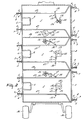
- Figure 2 shows schematically three adjacent milking parlours or boxes 1, which are separated from each other by partitions 26. Furthermore guide means 27, constituted by, for example, rods are provided with the object of giving the animal only a limited freedom of movement.
- Figure 2 shows two types of devices coupled to the udder of the animal, namely a cleaning and/or drying unit 28 and a milking unit 29. These units 28, 29 may be in a non-operative position outside the area bounded by the guide means 27.
- unit 28 can be moved to under the animal from one side, whilst unit 29 can be moved to under the animal from the other side.
- Both units have a support including two substantially vertical hinge pins 30, 31, the support in the region of hinge pin 30 being fastened to the floor, so that the unit 28, 29 is capable of movement within a predetermined area.
- means are present for moving the units 28, 29 in the upward direction, as will be explained in greater detail hereinafter.
- Unit 28 includes a bowl 16 ( Figure 3) which is substantially in close contact around the animal's udder and has a plurality of spraying nozzles 32 for spraying a cleaning liquid against the animals udder, and a central aperture 33 for discharging used-up cleaning liquid and also for supplying air, which optionally may have been heated, with the object of drying the udder after cleaning.
- Unit 29 includes a milking cluster 34 which is connectable to the teats of the udder and a shield 35, as will be explained in greater detail in the sequel.
- the storage containers 10, 11 and 12 described in the foregoing, which can optionally be provided over the boxes 1, can extend over a plurality of boxes, whilst it is optionally alternatively possible to provide one or a plurality of storage containers for each box.
- the described device for milking animals may be in the form of a mobile unit or built in a movable container which can in its totality be positioned in a desired location.
- the device may be provided, for this purpose, with wheels 36 (Figure 2), or other means useful for moving the implement. So as to enable positioning of the device in the open air, it may be provided with a roof 37 extending along the overall device ( Figure 1).
- FIG 3 shows in greater detail the unit 28 already shown in Figure 2.
- the unit 28 includes a bowl 16 which can be moved to under the animal and around its udder by means of support 17.
- Support 17 is capable of swivelling around hinge pin 30, the support being fastened to the floor in the region of this hinge pin.
- the support includes a first electric motor 38 for moving the device 38 upwards, for example by means of a spindle arranged concentrically to pin 30. Additionally, a second electric motor 39 is provided, so that swivelling around pin 30 of the support can be effected.
- the support furthermore comprises a second, substantially vertical hinge pin 31 whereby connecting members 40 and 41 of the support are capable of swivelling relative to each other.
- the connecting member 41 bears the bowl 16, which is provided with spray nozzles 32 and a central aperture 33.
- the aperture 33 provided centrally in the bowl 16 is made in the spot where the connecting member 41 is connected to the bowl 16.
- a liquid for example warm water
- the used-up liquid can be discharged through outlet 33 and conduit 43 to any place outside the milking device.
- device 19 can optionally apply warm air through conduit 44, which air is also passed to the udder through aperture 33.
- a non-return valve 45 is provided in the embodiment shown in Figure 3 in conduit 44, which valve passes the air current supplied, but constitutes a shut-off means for any liquid from the other direction.
- conduit 43 is provided with an S-curve, so that a liquid lock is formed, to ensure that the air supplied through conduit 44 cannot flow away through conduit 43.
- the milking device as shown in Figure 3 is computer-controlled, such that the bowl 16 first assumes an appropriate position in a substantially horizontal plane, whereafter the bowl is moved up, so that it is in a position around the udder of the animal. So as to facilitate this procedure, the edge of the bowl is provided with a strip 46 of a flexible material.
- the conduits 42, 43 and 44 must be adequately flexible to follow the motions of the bowl 16.
- moving the bowl is effected by a first electric motor 38, which can adjust the unit in the vertical direction, a second electric motor 39 being present for rotation around the pin 30 and a third electric motor being present for the mutual rotation of the connecting members 40 and 41 around the pin 31.
- the computer is connected to each one of said motors by means of electric connections 48.
- FIG 4 shows the unit 29 (see Figure 2).
- the unit comprises a milking cluster having four teat cups 52.
- These teat cups 52 may be of a conventional structure, but they may alternatively be of somewhat more flaring construction to facilitate connection to the teats.
- the support shown in Figure 4 is of the same type as shown in, and described with reference to, Figure 3.
- the milking cluster can be moved to any desired position to enable its connection to the udder.
- the spindle 49 for height adjustment of the unit is shown schematically.
- the arrangement shown in Figure 4 is provided with a plate 35 having a folded edge 51 at its top.
- the plate 35 has for its object to provide a shield between the hind legs of the animal and the milking cluster, more specifically for preventing the milking cluster from being contaminated.
- FIG. 5 shows a side view along the line V-V of Figure 4, in which further details of the milking cluster are shown.
- each teat cup 52 is connected, capably of hinging, to a central support 54, so that relative to the central support 54, each teat cup 52 is movable in a certain area.
- each teat cup can be positioned relative to the central support 54 with the aid of the computer, so that the four teat cups 52, which together form the milking cluster, are arranged in a configuration which is adapted to the relevant animal.
- Figure 6 shows schematically a mobile milking device comprising three milking parlours and being located in, for example, a meadow, so that animals 2, for example cows, walk around the implement.
- Figure 7 shows a trailer placed behind a tractor, which trailer is provided with different storage containers 57, 59 and 60, for, for example, liquid, milk and fodder, respectively.
- the device for milking animals can also be incorporated in any type of stable, the following description is based on a situation in which the milking device is installed in a meadow, as shown in Figure 6.
- each animal has a collar with a receiver attached thereto, which is connected to a loudspeaker located in the region of the animal's ears.
- a computer-controlled transmitter In the milking device is a computer-controlled transmitter, so that the computer can convey a call signal through the loudspeaker of the relevant cow.
- each desired animal can be invited to go to the milking parlour by means of, for example, agreeable sounds, as the animal then knows that there is, for example, concentrate available.
- the animals whose presence in the neighbourhood of the milking parlour is undesired may be given an unpleasant signal as soon as they are too close near the milking parlour.
- sound signals generated by means of a loudspeaker denoted by 61 in Figure 1.
- sensor means of the milking device will sense the presence of a certain animal, after door 3 ( Figure 1) has been opened by the computer so as to allow admittance to the milking parlour for the relevant animal.
- the computer supplies a predetermined, metered quantity of concentrate to the manger and a device for cleaning the udders is coupled to the udders. Because the animal eats the fodder supplied, it is in a given position and the computer can control the units to be coupled to the udder in such a manner that they are coupled in the appropriate way.
- a drying operation can follow after a cleaning operation, whereafter the device coupled to the udder moves back to its starting position and the milking cluster can be moved to under the animal from the other side and be coupled to the udder, also controlled by the computer, the mutual positions of the teat cups having been adapted to the udder of the specific animal.
- the milking cluster After the milking cycle has been terminated, the milking cluster returns to its starting position, whereafter door 4 is opened and both the door and the manger are moved, so that the animal can leave the milking parlour.
- the computer has the disposition of the relevant data of each animal, on the basis of which data the units 28, 29 are controlled.
- a loudspeaker 25 provided in the milking parlour wall ( Figure 1).
- This loudspeaker can be used in the first place for luring the animal, by producing a sound pleasant to the animal, for example a certain type of music. During milking, this music can be varied such that it promotes the milk production, for example by starting slowly and gradually passing into a more dynamic form.
- the same loudspeaker 25 can be used to encourage the animal to leave the milking parlour, by, for example, producing unpleasant sounds, for example shrill sounds.
- the animal decide itself whether it wants to be milked, for which purpose the sensor means detect the presence of the relative animal, whereafter that animal is permitted to enter the milking parlour.
- the sensor means detect the presence of the relative animal, whereafter that animal is permitted to enter the milking parlour.
Abstract
Description
- The invention relates to a device for milking animals, such as cows, comprising at least one milking parlour and a computer controlled milking machine.
- Generally, the milking parlour is a space where the animal can stand comfortably and where the necessary hygiene is observed.
- Milking is effected by means of a milking machine having one or more milking clusters with teat cups attachable to the teats of the udder, whereafter the milking machine produces a vacuum in the cups, causing the milk to be sucked from the udder, eiter pulsatingly or non-pulsatingly.
- During milking several measurements can be effected, such as a flow rate measurement, a temperature measurement, and furthermore sensors for recording relevant parameters may be present.
- In addition, the animal can be fed during milking, for example with concentrated fodder, it being possible to bring the quantity of fodder fed-forward depending on prevailing circumstances and the relevant animal. To that end, the animal can be provided with identifying means for detecting which animal is present in the milking parlour. With the aid of data, stored in the computer, the required quantity of fodder can be determined and be provided.
- In such a device the animals should go to the milking parlour. The animal can go there of its own accord, lured there by concentrate. However, it may be difficult to get specific animals at a specific moment selectively in the milking parlour.
- EP-A-0 091 892 refers to a cow recognizing system, to recognize which specific animal is present in the feeding box. This recognizing system comprises a transponder attached to a necklace; so, a signal can be omitted by means of a signal emitter on a necklace around the neck of an animal. This signal, which has to identify the animal, is received by a sensor placed adjacent the feeding station and further transmitted to a computer system for controlling means which dispense a certain amount of food, dependent of the specific animal.
- From US-A-4 010 714 it is known that, sending sound signals to cows, these animals react in a conditioned reflex to these signals.
- Furthermore from US-A-3 137 271 a method and a device is known for tending domestic animals. Hereby a tape recorder is mounted on the animal, which on a prescribed time, by means of a time device, starts playing a tape with instructions for the cow.
- The invention has for its object to provide a device for selectively milking animals, and actions by operating staff being reduced to a minimum.
- According to the invention, the computer further controlles signalling means for producing sound signals to be recognized by a specific animal as an instruction to go to or to leave the milking parlour, or to prevent an animal to enter or to approach the milking parlour.
- From the above mentioned it will be clear that by producing sound signals, which form an instruction for a specific animal to go to or to leave the milking parlour, or to prevent an animal to enter or to approach the milking parlour, a selectively milking of the animals is realised.
- According to a further characteristic of the invention, the sound signals can be emitted via a loudspeaker provided near the animal's ears.
- In accordance with a further characteristic of the invention, sound signals can be adapted to the animal's presence in the milking parlour and matched to the milking procedure. For example, the sound may be music, which is slow at the beginning of the milking procedure. Thereafter, when the supply of milk is at its maximum, a dynamic sound or dynamic music may be prduced.
- Further, in accordance with a characteristic of the invention, there can be emitted disagreeable and/or shrill sound signals, which are applied to animals which are near the milking device and are not wanted there and to animals which have to leave the milking parlour after the supply of milk or otherwise have to be set in motion.
- In accordance with a further characteristic, a loudspeaker can be attached to the collar of the animal, which collar may also carry identifying means for recognizing the animal.
- In accordance with further characteristics of the invention, a loudspeaker may be fitted in a side wall of the milking parlour. According to a characteristic of the invention, adjoining milking parlours can be separated from each other by a partition, so that animals in adjoining milking parlours are not disturbed by sound produced in the other milking parlour.
- In accordance with another characteristic of the invention, the signals may cover a predetermined area, so that sound is, for example, only received by the animals which are near the milking parlour.
- The invention further relates to a method for milking animals, such as cows, whereby the milking parlour is opened automatically when the animal is near the milking parlour and, when the animal is in the milking parlour, the milking cluster of a milking machine will be attached to the udder of the animal, characterized by emitting computer controlled sounds, which can be recognized by a specific animal as an instruction to go to the milking parlour.
- Furthermore according to the invention, after milking has ended, special sound signals are generated, urging the animal to leave the milking parlour.
- For a better understanding of the invention an embodiment of the device for milking animals will now be described with reference to the accompanying drawing.
- Figure 1 is a schematic cross-sectional view of a device for milking animals;
- Figure 2 is a schematical view along line II-II of Figure 1;
- Figure 3 is a schematic view of a cleaning and/or drying unit for the udder, which can be coupled automatically to the udder of the animal;
- Figure 4 is a schematic view of a milking unit which can be coupled automatically to the udder of the animal;
- Figure 5 shows schematically a side view along the line V - V of Figure 4;
- Figure 6 shows schematically an installed device for milking animals, and
- Figure 7 shows schematically a service vehicle for the device of Figure 6.
- Corresponding components in the several Figures are given the same reference numerals.
- Figure 1 shows a device including a box 1 (milking parlour) for the
animal 2, thisbox 1 having adoor 3 through which theanimal 2 can enter the box and a door 4 through which the animal can leave thebox 1. Bothdoors 3, 4 are connected such to the device that their orientation remains substantially the same during opening and closing. To that end a parallelogram structure is present, includingguide rods 5 which are connected hingeably to the frame of the device by means of theirends 6 and whoseother ends 7 are connected capable of hinging to thesupports 8 provided on the door. Figure 1 shows the twodoors 3, 4 in their closed positions, whilst the open position is illustrated by means of dotted lines. The use of a parallelogram structure for operating thedoors 3, 4 has the advantage that only a limited space is required for opening of the doors. Both doors are operable with the aid of control members, not shown, such as hydraulic or pneumatic cylinders, which can be applied and operated in known manner. As is shown in Figure 1, amanger 9 is attached to the door 4 from which theanimal 2 can eat concentrate or another kind of fodder during its stay in thebox 1. Because, on opening of the door 4, also themanger 9 is removed, the animal will tend to leave thebox 1 earlier than otherwise. - Three
storage containers box 1 for theanimal 2.Storage container 10 is intended for fodder, for example concentrate, the animal can eat during its stay in thebox 1. Thestorage container 10 has a fill opening 13 and a metering discharge outlet 14, which in answer to a control signal, feeds a predetermined quantity of fodder to themanger 9. Thestorage container 10 may be of such a construction that, as shown in Figure 1, the fodder can flow to the manger without any additional conveyor means. -
Storage container 11 is intended for storing milk and for that purpose, can comprise means for cooling the milk stored in the container. Storage container 12 is intended to store a cleaning fluid, for example water, which can be used for cleaning, disinfecting and rinsing parts coming into contact with the milk, such as milk pipes, the milking cluster, the udder, or further parts eligible for cleaning or rinsing. - Figure 1 also shows a
unit 15 which can be coupled to the udder of theanimal 2.Unit 15 includes a bowl 16 which is in an almost close contact around the cow's udder and is supported in the centre by asupport 17 which is attached to the floor and will be further described in the sequel with reference to Figure 3. - In addition, there is a
device 18 for conveying milk to thestorage tank 11. Device 19 has for its object to heat air and to convey that heated air to the udder-couplable device 15, as will be described in greater detail hereinafter. Usingdevice 20, the detergent can be pumped from the storage container 12 to the udder-couplable arrangement 15. The conveyor conduits 21 required for this purpose are shown schematically. - A collar 22 is provided around the animal's neck, to which means 23 for identifying the animal are fastened. These means 23 may be constituted by an electronic or magnetic information carrier or a transmitter transmitting a signal which is specific to the given
animal 2. Additionally, the device includes acomputer 24 which controls the several functions of the device. For that purpose thecomputer 24 is connected to different portions of the device, which is illustrated in Figure 1 by means of lines. - The device further includes a
loudspeaker 25 for producing sound or music so as to pass the desired signals on to the animal. - Figure 2 shows schematically three adjacent milking parlours or
boxes 1, which are separated from each other bypartitions 26. Furthermore guide means 27, constituted by, for example, rods are provided with the object of giving the animal only a limited freedom of movement. Figure 2 shows two types of devices coupled to the udder of the animal, namely a cleaning and/or dryingunit 28 and amilking unit 29. Theseunits box 1,unit 28 can be moved to under the animal from one side, whilstunit 29 can be moved to under the animal from the other side. Both units have a support including two substantially vertical hinge pins 30, 31, the support in the region ofhinge pin 30 being fastened to the floor, so that theunit units -
Unit 28 includes a bowl 16 (Figure 3) which is substantially in close contact around the animal's udder and has a plurality of sprayingnozzles 32 for spraying a cleaning liquid against the animals udder, and acentral aperture 33 for discharging used-up cleaning liquid and also for supplying air, which optionally may have been heated, with the object of drying the udder after cleaning. -
Unit 29 includes a milkingcluster 34 which is connectable to the teats of the udder and ashield 35, as will be explained in greater detail in the sequel. - The
storage containers boxes 1, can extend over a plurality of boxes, whilst it is optionally alternatively possible to provide one or a plurality of storage containers for each box. - The described device for milking animals may be in the form of a mobile unit or built in a movable container which can in its totality be positioned in a desired location. Optionally the device may be provided, for this purpose, with wheels 36 (Figure 2), or other means useful for moving the implement. So as to enable positioning of the device in the open air, it may be provided with a
roof 37 extending along the overall device (Figure 1). - Figure 3 shows in greater detail the
unit 28 already shown in Figure 2. Theunit 28 includes a bowl 16 which can be moved to under the animal and around its udder by means ofsupport 17.Support 17 is capable of swivelling aroundhinge pin 30, the support being fastened to the floor in the region of this hinge pin. The support includes a firstelectric motor 38 for moving thedevice 38 upwards, for example by means of a spindle arranged concentrically to pin 30. Additionally, a secondelectric motor 39 is provided, so that swivelling aroundpin 30 of the support can be effected. The support furthermore comprises a second, substantiallyvertical hinge pin 31 whereby connectingmembers 40 and 41 of the support are capable of swivelling relative to each other. At its end, the connecting member 41 bears the bowl 16, which is provided withspray nozzles 32 and acentral aperture 33. Theaperture 33 provided centrally in the bowl 16 is made in the spot where the connecting member 41 is connected to the bowl 16. - A liquid, for example warm water, can be applied to the
spray nozzles 32 throughconduit 42 by means of device 20 (Figure 1). The used-up liquid can be discharged throughoutlet 33 and conduit 43 to any place outside the milking device. So as to enable drying of the udders after cleaning, device 19 (Figure 1) can optionally apply warm air throughconduit 44, which air is also passed to the udder throughaperture 33. - So as to ensure that the air applied through
conduit 44 and the liquid discharged through conduit 43 can not mutually affect each other, anon-return valve 45 is provided in the embodiment shown in Figure 3 inconduit 44, which valve passes the air current supplied, but constitutes a shut-off means for any liquid from the other direction. Additionally, conduit 43 is provided with an S-curve, so that a liquid lock is formed, to ensure that the air supplied throughconduit 44 cannot flow away through conduit 43. - The milking device as shown in Figure 3 is computer-controlled, such that the bowl 16 first assumes an appropriate position in a substantially horizontal plane, whereafter the bowl is moved up, so that it is in a position around the udder of the animal. So as to facilitate this procedure, the edge of the bowl is provided with a
strip 46 of a flexible material. Theconduits electric motor 38, which can adjust the unit in the vertical direction, a secondelectric motor 39 being present for rotation around thepin 30 and a third electric motor being present for the mutual rotation of the connectingmembers 40 and 41 around thepin 31. To that end, the computer is connected to each one of said motors by means ofelectric connections 48. - Figure 4 shows the unit 29 (see Figure 2). The unit comprises a milking cluster having four
teat cups 52. These teat cups 52 may be of a conventional structure, but they may alternatively be of somewhat more flaring construction to facilitate connection to the teats. The support shown in Figure 4 is of the same type as shown in, and described with reference to, Figure 3. Using the computer-controlledelectric motors - At one side of the milking cluster the arrangement shown in Figure 4 is provided with a
plate 35 having a foldededge 51 at its top. Theplate 35 has for its object to provide a shield between the hind legs of the animal and the milking cluster, more specifically for preventing the milking cluster from being contaminated. - Figure 5 shows a side view along the line V-V of Figure 4, in which further details of the milking cluster are shown. In accordance with Figure 5, each
teat cup 52 is connected, capably of hinging, to acentral support 54, so that relative to thecentral support 54, eachteat cup 52 is movable in a certain area. By means of smallelectric motors central support 54 with the aid of the computer, so that the fourteat cups 52, which together form the milking cluster, are arranged in a configuration which is adapted to the relevant animal. - Figure 6 shows schematically a mobile milking device comprising three milking parlours and being located in, for example, a meadow, so that
animals 2, for example cows, walk around the implement. - Figure 7 shows a trailer placed behind a tractor, which trailer is provided with
different storage containers - Using the tractor and trailer combination shown in Figure 7, a trip can be made to the milking device of Figure 6, with the object of collecting milk and of bringing fodder and liquid.
- Although the device for milking animals can also be incorporated in any type of stable, the following description is based on a situation in which the milking device is installed in a meadow, as shown in Figure 6.
- The animals walk freely around the automatic milking device. The object in mind is that all the animals make a more or less regular appearance in a milking parlour of the milking device, to be milked there. For that purpose the animals can be lured to the milking parlour by the presence of concentrate, it is however alternatively possible to call the animals by means of sound signals. To that end, each animal has a collar with a receiver attached thereto, which is connected to a loudspeaker located in the region of the animal's ears. In the milking device is a computer-controlled transmitter, so that the computer can convey a call signal through the loudspeaker of the relevant cow. Thus, each desired animal can be invited to go to the milking parlour by means of, for example, agreeable sounds, as the animal then knows that there is, for example, concentrate available. Simultaneously, the animals whose presence in the neighbourhood of the milking parlour is undesired, may be given an unpleasant signal as soon as they are too close near the milking parlour. Instead of radio signals, it is alternatively possible to use sound signals generated by means of a loudspeaker, denoted by 61 in Figure 1. Since also identifying means are fastened to the collar of the cow, for example a transmitter transmitting given signals, sensor means of the milking device will sense the presence of a certain animal, after door 3 (Figure 1) has been opened by the computer so as to allow admittance to the milking parlour for the relevant animal. Depending on that specific animal, the computer supplies a predetermined, metered quantity of concentrate to the manger and a device for cleaning the udders is coupled to the udders. Because the animal eats the fodder supplied, it is in a given position and the computer can control the units to be coupled to the udder in such a manner that they are coupled in the appropriate way. A drying operation can follow after a cleaning operation, whereafter the device coupled to the udder moves back to its starting position and the milking cluster can be moved to under the animal from the other side and be coupled to the udder, also controlled by the computer, the mutual positions of the teat cups having been adapted to the udder of the specific animal. After the milking cycle has been terminated, the milking cluster returns to its starting position, whereafter door 4 is opened and both the door and the manger are moved, so that the animal can leave the milking parlour. To enable correct coupling of the relevant unit to the udder, the computer has the disposition of the relevant data of each animal, on the basis of which data the
units - In connection with an optimal milk production it is of utmost importance that the animal feels comfortable in all situations or is even positively influenced. This influencing can be done by means of sounds produced by a
loudspeaker 25 provided in the milking parlour wall (Figure 1). This loudspeaker can be used in the first place for luring the animal, by producing a sound pleasant to the animal, for example a certain type of music. During milking, this music can be varied such that it promotes the milk production, for example by starting slowly and gradually passing into a more dynamic form. Thesame loudspeaker 25 can be used to encourage the animal to leave the milking parlour, by, for example, producing unpleasant sounds, for example shrill sounds. - It may also be advantageous to have the animal decide itself whether it wants to be milked, for which purpose the sensor means detect the presence of the relative animal, whereafter that animal is permitted to enter the milking parlour. Thus, it is possible to raise milking to very many times per day, depending on the own needs of the animal, which may be advantageous for the milk production.
- It is of course alternatively possible to incorporate the milking arrangement in an open stable or in any other type of stable.
Claims (10)
- A device for milking animals, such as cows, comprising a milking parlour (1) and a computer controlled milking machine (15), characterized in that the computer (24) further controls signalling means (25) for producing sound signals to be recognized by a specific animal as an instruction to go to or to leave the milking parlour, or to prevent an animal to enter or to approach the milking parlour.
- A device as claimed in claim 1, characterized in that sound signals can be emitted via a loudspeaker (25) provided near the animal's ears (2).
- A device as claimed in claim 2, characterized in that sound signals can be adapted to the animal's presence in the milking parlour (1) and matched to the milking procedure.
- A device as claimed in claim 2 or 3, characterized in that disagreeable and/or shrill sound signals can be emitted, which are applied to animals which are near the milking device (15) and are not wanted there and to animals which have to leave the milking parlour (1) after the supply of milk or otherwise have to be set in motion.
- A device as claimed in any one of the preceding claims, characterized in that a loudspeaker can be attached to the collar (22) of the animal (2), which collar (22) may also carry identifying means (23) for recognizing the animal (2).
- A device as claimed in any one of the preceding claims, characterized in that a loudspeaker (25) may be fitted in a side wall of the milking parlour (1).
- A device as claimed in claim 6, characterized in that adjoining milking parlours (1) can be separated from each other by a partition, so that animals in adjoining milking parlours (1) are not disturbed by sound produced in the other milking parlour (1).
- A device as claimed in any one of the preceding claims, characterized in that the signals cover a predetermined area.
- A method for milking animals, such as cows, whereby the milking parlour (1) is opened automatically when the animal (2) is near the milking parlour (1), and in that, when the animal (2) is in the milking parlour (1), the milking cluster (34) of a milking machine (15) will be attached to the udder of the animal (2), characterized by emitting computer controlled sound signals, which can be recognized by a specific animal as an instruction to go to the milking parlour (1).
- A method as claimed in claim 9, characterized in that, after milking has ended, special sound signals are generated, urging the animal (2) to leave the milking parlour (1).
Priority Applications (8)
| Application Number | Priority Date | Filing Date | Title |
|---|---|---|---|
| EP94202464A EP0630562B1 (en) | 1985-01-16 | 1986-01-15 | Device for automatically milking animals |
| EP94202067A EP0630561B2 (en) | 1985-01-16 | 1986-01-15 | A device for automatically milking animals |
| EP89107977A EP0332232B2 (en) | 1985-01-16 | 1986-01-15 | Device for milking animals, such as cows |
| EP89107975A EP0332230B2 (en) | 1985-01-16 | 1986-01-15 | Device for milking animals, such as cows |
| AT86200064T ATE74254T1 (en) | 1985-01-16 | 1986-01-15 | EQUIPMENT AND METHOD FOR MILKING ANIMALS SUCH AS COWS. |
| EP89107974A EP0332229B2 (en) | 1985-01-16 | 1986-01-15 | Device for milking animals, such as cows |
| EP94202761A EP0630566B1 (en) | 1985-01-16 | 1986-01-15 | A device for automatically milking animals |
| EP89107976A EP0332231B2 (en) | 1985-01-16 | 1986-01-15 | Device for milking animals, such as cows |
Applications Claiming Priority (6)
| Application Number | Priority Date | Filing Date | Title |
|---|---|---|---|
| NL8500091 | 1985-01-16 | ||
| NL8500090A NL192812C (en) | 1985-01-16 | 1985-01-16 | Method for milking animals, such as cows, at a milking parlor from a free-flowing herd. |
| NL8500090 | 1985-01-16 | ||
| NL8500089A NL192241C (en) | 1985-01-16 | 1985-01-16 | Device for milking animals, such as cows. |
| NL8500091A NL8500091A (en) | 1985-01-16 | 1985-01-16 | Implement for milking cows - includes milking machine and signal generator to control movement of cows |
| NL8500089 | 1985-01-16 |
Related Child Applications (8)
| Application Number | Title | Priority Date | Filing Date |
|---|---|---|---|
| EP89107976A Division EP0332231B2 (en) | 1985-01-16 | 1986-01-15 | Device for milking animals, such as cows |
| EP89107975.8 Division-Into | 1986-01-15 | ||
| EP89107975A Division EP0332230B2 (en) | 1985-01-16 | 1986-01-15 | Device for milking animals, such as cows |
| EP89107974A Division EP0332229B2 (en) | 1985-01-16 | 1986-01-15 | Device for milking animals, such as cows |
| EP89107977A Division EP0332232B2 (en) | 1985-01-16 | 1986-01-15 | Device for milking animals, such as cows |
| EP89107976.6 Division-Into | 1989-05-03 | ||
| EP89107977.4 Division-Into | 1989-05-03 | ||
| EP89107974.1 Division-Into | 1989-05-03 |
Publications (2)
| Publication Number | Publication Date |
|---|---|
| EP0189954A1 EP0189954A1 (en) | 1986-08-06 |
| EP0189954B1 true EP0189954B1 (en) | 1992-04-01 |
Family
ID=27352122
Family Applications (8)
| Application Number | Title | Priority Date | Filing Date |
|---|---|---|---|
| EP94202464A Expired - Lifetime EP0630562B1 (en) | 1985-01-16 | 1986-01-15 | Device for automatically milking animals |
| EP94202465A Withdrawn EP0630563A2 (en) | 1985-01-16 | 1986-01-15 | Device for automatically milking animals |
| EP94202065A Withdrawn EP0630559A1 (en) | 1985-01-16 | 1986-01-15 | A device for automatically milking animals |
| EP94202761A Expired - Lifetime EP0630566B1 (en) | 1985-01-16 | 1986-01-15 | A device for automatically milking animals |
| EP86200064A Expired - Lifetime EP0189954B1 (en) | 1985-01-16 | 1986-01-15 | Implement and method for milking animals, such as cows |
| EP94202067A Expired - Lifetime EP0630561B2 (en) | 1985-01-16 | 1986-01-15 | A device for automatically milking animals |
| EP94202762A Withdrawn EP0630567A2 (en) | 1985-01-16 | 1986-01-15 | An implement for automatically milking animals |
| EP94202066A Withdrawn EP0630560A1 (en) | 1985-01-16 | 1986-01-15 | A device for automatically milking animals |
Family Applications Before (4)
| Application Number | Title | Priority Date | Filing Date |
|---|---|---|---|
| EP94202464A Expired - Lifetime EP0630562B1 (en) | 1985-01-16 | 1986-01-15 | Device for automatically milking animals |
| EP94202465A Withdrawn EP0630563A2 (en) | 1985-01-16 | 1986-01-15 | Device for automatically milking animals |
| EP94202065A Withdrawn EP0630559A1 (en) | 1985-01-16 | 1986-01-15 | A device for automatically milking animals |
| EP94202761A Expired - Lifetime EP0630566B1 (en) | 1985-01-16 | 1986-01-15 | A device for automatically milking animals |
Family Applications After (3)
| Application Number | Title | Priority Date | Filing Date |
|---|---|---|---|
| EP94202067A Expired - Lifetime EP0630561B2 (en) | 1985-01-16 | 1986-01-15 | A device for automatically milking animals |
| EP94202762A Withdrawn EP0630567A2 (en) | 1985-01-16 | 1986-01-15 | An implement for automatically milking animals |
| EP94202066A Withdrawn EP0630560A1 (en) | 1985-01-16 | 1986-01-15 | A device for automatically milking animals |
Country Status (3)
| Country | Link |
|---|---|
| EP (8) | EP0630562B1 (en) |
| AT (3) | ATE120928T1 (en) |
| DE (8) | DE3689481T3 (en) |
Cited By (1)
| Publication number | Priority date | Publication date | Assignee | Title |
|---|---|---|---|---|
| DE202007016519U1 (en) | 2007-11-23 | 2008-06-12 | Fisch, Wolfgang | Device for the keeping of animals |
Families Citing this family (49)
| Publication number | Priority date | Publication date | Assignee | Title |
|---|---|---|---|---|
| NL8502434A (en) * | 1985-09-04 | 1987-04-01 | Multinorm Bv | MILK MACHINE. |
| DE3638221A1 (en) * | 1986-11-08 | 1988-05-19 | Irps Hartwig | Barn and pasture milking parlor for dairy cows |
| NL8602942A (en) | 1986-11-19 | 1988-06-16 | Multinorm Bv | MOVABLE ROOM CONTAINING AN AUTOMATIC MILKING DEVICE OF AN ANIMAL. |
| DE3702465A1 (en) * | 1987-01-28 | 1988-08-11 | Duevelsdorf & Sohn Gmbh & Co K | METHOD AND DEVICE FOR MILKING AND GGFS. FEEDING OF FREEDOMING, IDENTIFICATION-BASED COWS |
| FI78595C (en) * | 1987-07-22 | 1989-09-11 | Taittometalli Oy | Washing device for a teat. |
| US4977856A (en) * | 1988-11-25 | 1990-12-18 | Dairyland Automation, Inc. | Rapid exit parlor system |
| NL8900415A (en) * | 1989-02-21 | 1990-09-17 | Lely Nv C Van Der | STAY FOR A NUMBER OF ANIMALS, IN PARTICULAR MILK ANIMALS. |
| NL8900416A (en) * | 1989-02-21 | 1990-09-17 | Lely Nv C Van Der | DEVICE FOR CLEANING DAIRY ANIMALS. |
| US5195455A (en) * | 1989-02-21 | 1993-03-23 | C. Van Der Lely N.V. | Arrangement for keeping dairy animals clean |
| NL9101673A (en) * | 1991-10-04 | 1993-05-03 | Texas Industries Inc | Apparatus for cleaning teats of milking animals. |
| NL9200091A (en) * | 1992-01-17 | 1993-08-16 | Lely Nv C Van Der | MILK MACHINE. |
| JPH07502661A (en) * | 1992-11-02 | 1995-03-23 | シー バン デル レライ エヌ ヴィ | Construct for automatic milking of animals |
| NL9300443A (en) * | 1993-03-11 | 1994-10-03 | Prolion Bv | Method and device for monitoring animal functions. |
| NL9301317A (en) * | 1993-07-28 | 1995-02-16 | Lely Nv C Van Der | Device for automatic milking of animals. |
| NL9301318A (en) * | 1993-07-28 | 1995-02-16 | Lely Nv C Van Der | Device for automatic milking of animals. |
| NL9301377A (en) * | 1993-08-09 | 1995-03-01 | Lely Nv C Van Der | Device for automatic milking of animals. |
| US5596945A (en) * | 1994-07-01 | 1997-01-28 | Van Der Lely; Cornelis | Construction for automatically milking animals |
| NL9401801A (en) * | 1994-08-23 | 1996-04-01 | Maasland Nv | Construction with a device for milking animals. |
| NL9401802A (en) * | 1994-10-31 | 1996-06-03 | Maasland Nv | Device for milking animals. |
| WO1996019917A2 (en) * | 1994-12-28 | 1996-07-04 | Tetra Laval Holdings & Finance S.A. | An apparatus for and a method of managing animals |
| NL1001336C1 (en) * | 1995-02-24 | 1996-08-28 | Maasland Nv | Construction with a device for milking animals. |
| US6472192B1 (en) | 1996-04-18 | 2002-10-29 | Consortium für elektrochemische Industrie GmbH | Cyclodextrin glycosyl transferases for producing γ-cyclodextrin |
| IL131747A0 (en) * | 1997-03-26 | 2001-03-19 | Alfa Laval Agri Ab | A method and an apparatus for preparing a lactating animal for milking |
| FR2776504B1 (en) * | 1998-03-25 | 2000-07-13 | Daniel Fourmond | DUMP FOR TRANSPORTATION AND BATHING OF BOVIDS |
| SE513949C2 (en) * | 1998-08-14 | 2000-12-04 | Alfa Laval Agri Ab | Milk robot and method for controlling the movement of the robot arm |
| SE513503C2 (en) * | 1998-08-26 | 2000-09-25 | Alfa Laval Agri Ab | Method and apparatus for controlling the movement of a robotic arm of a milking robot |
| NL1010304C2 (en) * | 1998-10-13 | 2000-04-17 | Maasland Nv | Device for feeding young animals. |
| NL1015435C2 (en) † | 2000-06-14 | 2002-01-04 | Lely Entpr Ag | Device for the successive reception and / or treatment of individual animals from a group of animals as well as a method for increasing the capacity of use of the device. |
| DE10110473B4 (en) | 2001-03-05 | 2005-02-03 | Maier Jun., Jakob | Automatic milking device with controllable stimulation device and system for stimulation |
| SE520347C2 (en) | 2001-10-08 | 2003-07-01 | Delaval Holding Ab | Procedure for handling animals and milking station respectively |
| DE10155546A1 (en) * | 2001-11-12 | 2003-05-28 | Westfalia Landtechnik Gmbh | Mobile automatic milking parlor |
| CN2643859Y (en) * | 2003-06-24 | 2004-09-29 | 宁波市科技园区拓普健康科技有限公司 | Multifunctional galactophore care instrument for cow |
| DK176415B1 (en) * | 2005-06-17 | 2008-01-07 | Asger Thorsen | Sorting unit for use in sorting animals |
| CN100464684C (en) * | 2007-02-08 | 2009-03-04 | 赵淑菊 | Mamma cleaner |
| DE102010016126A1 (en) | 2010-03-24 | 2011-09-29 | Hartmann Grundbesitz Gmbh & Co. Kg | Animal placement order |
| NZ605483A (en) | 2010-06-14 | 2015-08-28 | Milfos Internat Ltd | Improved milking apparatus and system |
| ES2408786B1 (en) * | 2011-10-25 | 2014-04-23 | Soutos Galegos, S.L. | AUTOMATED ENVIRONMENT FOR RETENTION, PRIMING AND CATCH OF LIVESTOCK IN FREEDOM. |
| DE102012215751A1 (en) * | 2012-09-05 | 2014-03-06 | Jakob Maier | Automatic cleaning system and method for cleaning / treating teats of a milk animal |
| CN105828600A (en) * | 2013-12-18 | 2016-08-03 | 利拉伐控股有限公司 | End effector, robot, and rotary milking system |
| EP3017689A1 (en) | 2014-11-06 | 2016-05-11 | Lemmer Fullwood GmbH | Method and device for automatic milking of animals at a configurable time |
| NL2015969B1 (en) * | 2015-12-16 | 2017-06-30 | Lely Patent Nv | Milking establishment |
| IES20180072A2 (en) * | 2017-04-12 | 2018-08-22 | Cashman William | A milking parlour |
| CN110545662B (en) * | 2017-05-02 | 2022-06-03 | 利拉伐控股有限公司 | Expelling device and milking installation provided with such a device |
| CN109042370A (en) * | 2018-08-22 | 2018-12-21 | 山东中梁农业发展有限责任公司 | A kind of rabbit milk artificial intelligence adopts milk system and its adopts milk method automatically |
| CA3124067A1 (en) * | 2018-12-17 | 2020-06-25 | Co-Exist Ltd | System and method for directing livestock animal |
| CN109892246B (en) * | 2019-04-28 | 2021-06-15 | 叶耀 | Automatic wool combing device used for fine wool sheep breeding and based on wool thickness |
| US11051484B2 (en) | 2019-10-02 | 2021-07-06 | Farm Improvements Limited | Sprayer with articulated arm and sensor system |
| CN110810267B (en) * | 2019-12-05 | 2021-06-15 | 塔里木大学 | Disinfection system for dairy cattle farm |
| CN114190282A (en) * | 2020-10-21 | 2022-03-18 | 生冬梅 | Livestock-raising is with breeding cage placer |
Family Cites Families (9)
| Publication number | Priority date | Publication date | Assignee | Title |
|---|---|---|---|---|
| US3137271A (en) * | 1963-02-06 | 1964-06-16 | Robert W Etter | Means and method for tending domestic animals |
| US4010714A (en) * | 1974-03-08 | 1977-03-08 | Director, National Institute Of Animal Industry | System for managing milking-cows in stanchion stool |
| FR2288460A1 (en) * | 1974-08-09 | 1976-05-21 | Anvar | ANIMALS SUCH AS COWS MILKING FACILITIES |
| US3980051A (en) * | 1975-05-16 | 1976-09-14 | Lawrence Peska Associates, Inc. | Range triggered animal training system |
| FR2348648A1 (en) * | 1976-04-23 | 1977-11-18 | Bottin Sprl Atel Nicholas | MOBILE MILKING STALL TRAILER AND FIXED MILKING BLOCK |
| FR2424700A1 (en) * | 1978-05-03 | 1979-11-30 | Abrahamson John | Milking machine control system - has regulator to apply lower vacuum to outside of liner than inside before starting to milk to close liner around teat |
| BE881731A (en) * | 1980-02-14 | 1980-05-30 | Nicolas Bottin Atel | MOBILE MILKING STALLS |
| FR2523809A1 (en) * | 1982-03-23 | 1983-09-30 | Kubler Andre | Transmission system for recalling domestic animals - uses receiver and loudspeakers in collar to receive modulated signal from portable transmitter |
| SE430559B (en) * | 1982-04-08 | 1983-11-28 | Alfa Laval Ab | SET FOR MILK AND DEVICE HERE |
-
1986
- 1986-01-15 AT AT89107976T patent/ATE120928T1/en not_active IP Right Cessation
- 1986-01-15 AT AT89107974T patent/ATE128001T1/en not_active IP Right Cessation
- 1986-01-15 EP EP94202464A patent/EP0630562B1/en not_active Expired - Lifetime
- 1986-01-15 EP EP94202465A patent/EP0630563A2/en not_active Withdrawn
- 1986-01-15 DE DE3689481T patent/DE3689481T3/en not_active Expired - Fee Related
- 1986-01-15 DE DE3650298T patent/DE3650298T3/en not_active Expired - Fee Related
- 1986-01-15 EP EP94202065A patent/EP0630559A1/en not_active Withdrawn
- 1986-01-15 EP EP94202761A patent/EP0630566B1/en not_active Expired - Lifetime
- 1986-01-15 EP EP86200064A patent/EP0189954B1/en not_active Expired - Lifetime
- 1986-01-15 AT AT89107975T patent/ATE128322T1/en not_active IP Right Cessation
- 1986-01-15 DE DE3650399T patent/DE3650399T3/en not_active Expired - Fee Related
- 1986-01-15 EP EP94202067A patent/EP0630561B2/en not_active Expired - Lifetime
- 1986-01-15 DE DE3650748T patent/DE3650748T2/en not_active Expired - Fee Related
- 1986-01-15 DE DE3650755T patent/DE3650755T2/en not_active Expired - Fee Related
- 1986-01-15 DE DE3650410T patent/DE3650410T3/en not_active Expired - Fee Related
- 1986-01-15 EP EP94202762A patent/EP0630567A2/en not_active Withdrawn
- 1986-01-15 DE DE8686200064T patent/DE3684619D1/en not_active Expired - Fee Related
- 1986-01-15 DE DE3650742T patent/DE3650742T2/en not_active Expired - Fee Related
- 1986-01-15 EP EP94202066A patent/EP0630560A1/en not_active Withdrawn
Cited By (1)
| Publication number | Priority date | Publication date | Assignee | Title |
|---|---|---|---|---|
| DE202007016519U1 (en) | 2007-11-23 | 2008-06-12 | Fisch, Wolfgang | Device for the keeping of animals |
Also Published As
Similar Documents
| Publication | Publication Date | Title |
|---|---|---|
| EP0189954B1 (en) | Implement and method for milking animals, such as cows | |
| EP0332229B2 (en) | Device for milking animals, such as cows | |
| EP0319523B1 (en) | Device for automatically milking an animal | |
| US5195455A (en) | Arrangement for keeping dairy animals clean | |
| US5865138A (en) | Method and apparatus for automatically milking animals, such as cows | |
| EP0634097B1 (en) | A construction for automatically milking animals | |
| EP0188303A1 (en) | Implement for automatically milking an animal | |
| WO1998005201A3 (en) | An implement for automatically milking animals | |
| JPH11506303A (en) | Livestock management device and management method | |
| EP0323444B1 (en) | A device for milking animals, such as cows | |
| EP1434480A1 (en) | Method of managing animals and milking station | |
| EP0638231B1 (en) | A construction for automatically milking animals | |
| NL8500090A (en) | Implement for milking cows - includes milking machine and signal generator to control movement of cows | |
| EP0886466A1 (en) | A construction including an implement for automatically milking animals | |
| NL8500091A (en) | Implement for milking cows - includes milking machine and signal generator to control movement of cows | |
| NL8500089A (en) | Implement for milking cows - includes milking machine and signal generator to control movement of cows | |
| JPH1189461A (en) | Milking method and equipment | |
| JPH1189466A (en) | Milking equipment | |
| JPH1189465A (en) | Milking equipment | |
| JPH1189462A (en) | Milking equipment |
Legal Events
| Date | Code | Title | Description |
|---|---|---|---|
| PUAI | Public reference made under article 153(3) epc to a published international application that has entered the european phase |
Free format text: ORIGINAL CODE: 0009012 |
|
| AK | Designated contracting states |
Kind code of ref document: A1 Designated state(s): AT BE CH DE FR GB IT LI NL SE |
|
| 17P | Request for examination filed |
Effective date: 19870204 |
|
| 17Q | First examination report despatched |
Effective date: 19890120 |
|
| GRAA | (expected) grant |
Free format text: ORIGINAL CODE: 0009210 |
|
| AK | Designated contracting states |
Kind code of ref document: B1 Designated state(s): AT BE CH DE FR GB IT LI NL SE |
|
| PG25 | Lapsed in a contracting state [announced via postgrant information from national office to epo] |
Ref country code: SE Effective date: 19920401 Ref country code: LI Effective date: 19920401 Ref country code: CH Effective date: 19920401 Ref country code: BE Effective date: 19920401 Ref country code: AT Effective date: 19920401 Ref country code: IT Free format text: LAPSE BECAUSE OF FAILURE TO SUBMIT A TRANSLATION OF THE DESCRIPTION OR TO PAY THE FEE WITHIN THE PRE;WARNING: LAPSES OF ITALIAN PATENTS WITH EFFECTIVE DATE BEFORE 2007 MAY HAVE OCCURRED AT ANY TIME BEFORE 2007. THE CORRECT EFFECTIVE DATE MAY BE DIFFERENT FROM THE ONE RECORDED.SCRIBED TIME-LIMIT Effective date: 19920401 Ref country code: NL Effective date: 19920401 |
|
| REF | Corresponds to: |
Ref document number: 74254 Country of ref document: AT Date of ref document: 19920415 Kind code of ref document: T |
|
| XX | Miscellaneous (additional remarks) |
Free format text: TEILANMELDUNG 89107974.1 EINGEREICHT AM 15/01/86. |
|
| REF | Corresponds to: |
Ref document number: 3684619 Country of ref document: DE Date of ref document: 19920507 |
|
| REG | Reference to a national code |
Ref country code: CH Ref legal event code: PL |
|
| ET | Fr: translation filed | ||
| NLV1 | Nl: lapsed or annulled due to failure to fulfill the requirements of art. 29p and 29m of the patents act | ||
| PLBE | No opposition filed within time limit |
Free format text: ORIGINAL CODE: 0009261 |
|
| STAA | Information on the status of an ep patent application or granted ep patent |
Free format text: STATUS: NO OPPOSITION FILED WITHIN TIME LIMIT |
|
| 26N | No opposition filed | ||
| REG | Reference to a national code |
Ref country code: GB Ref legal event code: IF02 |
|
| PGFP | Annual fee paid to national office [announced via postgrant information from national office to epo] |
Ref country code: GB Payment date: 20030108 Year of fee payment: 18 |
|
| PGFP | Annual fee paid to national office [announced via postgrant information from national office to epo] |
Ref country code: DE Payment date: 20030131 Year of fee payment: 18 |
|
| PG25 | Lapsed in a contracting state [announced via postgrant information from national office to epo] |
Ref country code: GB Free format text: LAPSE BECAUSE OF NON-PAYMENT OF DUE FEES Effective date: 20040115 |
|
| PGFP | Annual fee paid to national office [announced via postgrant information from national office to epo] |
Ref country code: FR Payment date: 20040122 Year of fee payment: 19 |
|
| PG25 | Lapsed in a contracting state [announced via postgrant information from national office to epo] |
Ref country code: DE Free format text: LAPSE BECAUSE OF NON-PAYMENT OF DUE FEES Effective date: 20040803 |
|
| GBPC | Gb: european patent ceased through non-payment of renewal fee |
Effective date: 20040115 |
|
| PG25 | Lapsed in a contracting state [announced via postgrant information from national office to epo] |
Ref country code: FR Free format text: LAPSE BECAUSE OF NON-PAYMENT OF DUE FEES Effective date: 20050930 |
|
| REG | Reference to a national code |
Ref country code: FR Ref legal event code: ST |