JP4065332B2 - Milking equipment and support equipment - Google Patents
Milking equipment and support equipment Download PDFInfo
- Publication number
- JP4065332B2 JP4065332B2 JP54912698A JP54912698A JP4065332B2 JP 4065332 B2 JP4065332 B2 JP 4065332B2 JP 54912698 A JP54912698 A JP 54912698A JP 54912698 A JP54912698 A JP 54912698A JP 4065332 B2 JP4065332 B2 JP 4065332B2
- Authority
- JP
- Japan
- Prior art keywords
- milking
- support
- arm
- nipple
- balance
- Prior art date
- Legal status (The legal status is an assumption and is not a legal conclusion. Google has not performed a legal analysis and makes no representation as to the accuracy of the status listed.)
- Expired - Fee Related
Links
Images


Classifications
-
- A—HUMAN NECESSITIES
- A01—AGRICULTURE; FORESTRY; ANIMAL HUSBANDRY; HUNTING; TRAPPING; FISHING
- A01J—MANUFACTURE OF DAIRY PRODUCTS
- A01J5/00—Milking machines or devices
- A01J5/017—Automatic attaching or detaching of clusters
Abstract
Description
本発明は、複数の乳首カップを備えた搾乳器材とその搾乳器材に連結された少なくとも一本の送乳ホースとを有する搾乳装置に関する。本発明は、また、搾乳装置の支援装置にも関するが、この搾乳装置は、ミルク取り出し用ニップルを持ったクローと、このクローに連結された乳首カップとを有する搾乳器材、前記ミルク取り出し用ニップルに連結された送乳ホース、および固定された支持部材を備え、固定された支持部材は、垂直な支持シャフトとほぼ水平なアームとを有し、ほぼ水平なアームは、その一端で支持シャフトに連結され、他端で送乳ホースの少なくとも一部分を支えている。
自由に歩行している雌牛は1日2回、特殊な搾乳牛舎で搾乳されるのが普通である。このような搾乳牛舎は搾乳される牛のための多数の間仕切りを有し、床が間仕切りよりも低くなっており、搾乳器材の乳首カップを牛の乳首に取り付けて作業中搾乳者は直立していることができる。乳首カップの取り付けを可能にするために、搾乳者は搾乳器材を一方の手で支えるが、そこでは搾乳器材が牛の乳房の下の適当な位置に置かれるように腕がかなり延ばされる。同時に搾乳者が他の空いている方の手で乳首カップを乳首に取り付ける。しかしながら、搾乳器材が比較的重く、かつ各搾乳時に搾乳される牛の数が膨大になることもあるので、搾乳者は、搾乳器材を持ち上げている腕とその肩に、圧迫による障害を受ける危険に曝されている。4個の乳首カップと1つのクローを有する従来の搾乳器材は、重さが普通約4kgである。それに加えて、搾乳者は、クローに取り付けてある送乳ホースの一部分を持ち上げなけれならない。
上述の種類の圧迫による障害の問題を克服することができる装置を提供することは以前から提案されている。例えば、SE−B−331 611は乳首カップ用のホルダ8を持った水平な結合部材5を有する搾乳器材の乳首カップ用支持部を開示している。こうして、搾乳者の両手が乳首カップを取り扱うために自由になるように、支持部材は搾乳器材を懸垂して保持する。しかしながら、既知の支持部材は比較的複雑で高価であり、まだ取り引きされていない。
DE−B−1278 166は、ピストンロッド4を持った水平シリンダ3を有する支持装置を開示しており、ここでは、ピストンロッドは、搾乳器材を運ぶ自由端を有する。このシリンダ3は、垂直なピストン−シリンダによって垂直に調節可能である。しかしながら、この既知の支持装置は複雑であり、乳首カップが取り付けられる時、搾乳器材の牛の乳房の下での自由度が不十分であるように思われる。
US−A−789 798は、水平な支持アーム32,33を有しこの支持アームは、その一端が垂直軸に取り付けられ、他の一端にクロー45が配置されている自動乳首カップ移動装置を開示している。この既知の自動乳首カップ移動装置もまた、複雑であり、乳首カップが取り付けられる時、搾乳器材の自由度が不十分である。
本発明の目的は、上述の圧迫による障害問題が解消されるような方法で、乳首カップの取付けを可能にする搾乳装置を提供することである。
この目的は当初に述べられ、かつ、次のような特徴を有する種類の搾乳装置により達成される。すなわち、搾乳器材と前記送乳ホースの少なくとも一部分とはバランス装置により支持されており、そのバランス装置は、搾乳者が搾乳器材の全重量を同時に支える必要なしに搾乳者が乳首カップを動物の乳首に当てることができるようにするために、そのバランス装置が搾乳器材の重量と送乳ホースの前記一部分の重量とをほぼバランスさせる取付位置と、乳首カップが乳首に取り付けられている時、搾乳器材の実質的に全重量が動物の乳首に作用する搾乳位置とに調節可能であることを特徴とする。
バランス装置は、非常に簡単で低コストで製造することができる。それは、一端が搾乳器材に取り付けられ他端が送乳ホースの前記一部分を支えるほぼ水平なバランスアームと、そのバランスアームを支える保持部材と、保持部材を支持する固定された支持部材とを有することが好ましい。ここで、バランスアームは、前記取付位置に一致し保持部材が搾乳器材に接近して配置されている第1の位置と、前記搾乳位置に一致し保持部材が搾乳器材から離れて配置されている第2の位置との間を保持部材に対し水平に移動させることができる。
都合好く、バランス装置は、搾乳器材が搾乳スペースに配置され前記スペースにいる動物に取り付け可能である作業位置と、搾乳器材が前記スペースの外に配置されている準備位置との間を、前記搾乳器材が移動できるように構成されている。支持部材は、垂直な支持シャフトと、一端で支持シャフトに連結され他端で保持部材に結合されるほぼ水平な支持アームとを有することができる。それにより、支持アームは、搾乳器材が前記作業位置と準備位置との間を移動可能なように、支持シャフトにより回転されることができる。
支持アームは、保持部材が支持シャフトから離れて配置されている第1位置と、保持部材が支持シャフトに接近して配置されている第2位置と、の間で調節可能であることが望ましい。支持アームが調節可能なことにより、バランス装置が前記取付位置に調節される時、動物の乳房の下方で搾乳器材の適切な調節が可能である。支持アームは、支持シャフトに連結される第1の部分と、保持部材に接続され支持アームの前記第1の部分に沿って移動可能である第2の部分とを有することができる。
搾乳が終わってから自動乳首カップ移動装置により乳首カップは動物の乳房から取外されるように配慮されていてもよい。このような場合、乳首カップ移動装置は、乳首カップが動物の乳房から取外された時、搾乳器材を作業位置から準備位置に移動させるように都合よく配慮されている。さらに、乳首カップ移動装置は、搾乳器材を作業位置から準備位置に移動する間にバランス装置を搾乳位置から取付位置に調節するように、都合好く配慮されている。通常、自動乳首カップ移動装置は、搾乳器材に取り付けられている引き出しコードを有する。このような引き出しコードは、支持アームの前記反対側の端にある支持アームの案内開口を通り、延びていることが望ましい。
本発明の更なる目的は、搾乳装置を取り扱う間に搾乳者が圧迫による障害を受けるリスクを減少する支援装置を提供することである。
この目的は、冒頭に述べられたタイプの搾乳装置用の支持装置により得られるが、その支援装置は、管状のバランスアームに特徴があり、そのバランスアームは、ミルク取り出し口ニップルの内側がバランスアームの内側を経て送乳ホースの内側と連通するように、クローのミルク取り出し口ニップルと送乳ホースとの間を連結可能であり、保持部材は、接続部材を経て、支持アームの前記他端において支持アームに連結可能であって、バランスアームを支えており、バランスアームがそこで保持された時、保持部材がクローに対して接近して配置されている第1の位置と、保持部材がクローから離れて配置されている第2の位置との間をバランスアームが保持部材に対し移動可能であり、それにより、保持部材とバランスアームとが搾乳装置内で連結された時、支持アームが、保持部材とバランスアームとを介して搾乳器材と送乳ホースの前記一部分とを支持することを特徴としている。
支持シャフトから保持部材までの距離を調節するための調節装置は、接続部材と支持シャフトとの間を連結可能であることが適当である。調節装置は、棒材と、その棒材がその中を通って移動できるようになっている案内スリーブとを有することができ、ここでは棒材が前記接続部材に連結可能であり、案内スリーブは支持シャフトに連結できる。
保持部材がスリーブを有し、そのスリーブはバランスアーム上に設けられ、かつバランスアームとスリーブ間に半径方向の遊びが設けられるような寸法となっていることが好ましい。これにより、バランスアームはスリーブを通って容易に滑動することができる。
次に、付図を参照して、本発明をより詳細に説明する。
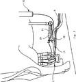
図1は、バランス装置が取付位置に調節されている本発明の搾乳装置を開示し、
図2は、図1の搾乳装置のバランス装置の拡大した詳細図を開示し、
図3は、搾乳中の搾乳装置を開示し、
図4は、乳首カップ移動装置が乳首カップを動物の乳房から取外そうとする時の搾乳装置を開示し、そして、
図5は、搾乳器材が準備位置にある搾乳装置を開示している。
図1は搾乳器材1を有する本発明の搾乳装置を開示しており、この搾乳装置はミルク取り出し口ニップルを持ったクロー(導乳管集約器)2とクロー2に接続された乳首カップ3とを有する搾乳器材1、前記ミルク取り出し口ニップルに接続された送乳ホース4および送乳ホース4に取り付けられた一対の脈動ホース5、並びに固定された支持部材6とを備える。支持部材6は、垂直な支持シャフト7と、ほぼ水平で弾性を持った支持アーム8を有し、この支持アーム8は、その一端が支持シャフト7に連結され、他端が接続部材9を介してスリーブ形状の保持部材10に連結されている。ミルク取り出し口ニップルの内側が管状のバランスアーム11の内側を介して送乳ホース4の内側と連通するような方法で、管状のバランスアームが、クロー2のミルク取り出し口ニップルと送乳ホース4との間に連結されている。保持部材10は、バランスアーム11上に設けられ、その寸法は、バランスアーム11とスリーブ形状の保持部材10との間に半径方向の遊びがあるようになっている。支持部材6と保持部材10とバランスアーム11とは、バランス装置を形成し、このバランス装置により、搾乳器材1の重量と送乳ホース4の一部分の重量とをほぼバランスさせることができる。
支持アーム8は、その一端で支持シャフト7に連結されたアーム13と、アーム13の他端に脱着可能に連結された案内スリーブ14とを有する構成部分12を備える。さらに、支持アーム8は、案内スリーブ14内を移動可能に設けられた棒材15を有し、そこでは、棒材15はアーム13に平行である。棒材15はその一端で接続部材9に連結されている。
この場合、図2に示されるように、接続部材9は、スリーブ形状の保持部材10内の半径方向の孔と棒材15内の孔とを通して案内される頭の膨らんだボルトを有し、このボルトは自動ロック式のナットを備えている。そうでなく、接続部材9は、別な様式で設計されてもよい。保持部材10が水平に回転可能で垂直な面内を幾分回動され得ることが重要である。
ピストン−シリダ部材17と引き出しコード18とを有する乳首カップ移動装置16は、開示されていない支持部に固定されている。引き出しコード18はピストン−シリダ部材17からクロー2まで延び、そこでクロー2に取り付けられている。引き出しコード18がそこを通って延びている案内開口部材19は、接続部材9の近くで棒材15に取り付けられている。
搾乳スペースAは、搾乳される動物のために設けられるが、ここでは、支持シャフト7と乳首カップ移動装置16とが搾乳スペースAの外側に設けられている。
諸図に開示されている本発明の搾乳装置は、次のような機能を持っている。動物、例えば牛が搾乳されるために搾乳スペースAに配置されると、搾乳者は支持シャフト7によって搾乳器材1を、搾乳スペースA内の準備位置(図5)から牛の乳房のほぼ下方の作業位置へ回転させる。搾乳者は、案内スリーブ14に対する棒材15の位置を調節することにより、クロー2が牛の乳首の真下に配置されるように搾乳器材1と支持シャフト7との間の距離を調節する。ここで、保持部材10は、バランスアーム上でクローに近接して配置され、送乳ホース4の一部が搾乳器材1の重量に対するバランスウエートとなるように上記バランス装置が妥当な位置に調節される。(脈動ホース5の重量も、また上記バランスウエートとして多少貢献する)。したがって、搾乳器材1の重量と送乳ホース4の上記部分の重量がバランスしていることが重要である。これにより、搾乳者が搾乳器材1の全重量を同時に支える必要なしに乳首カップ3を牛の乳房に取り付けることができる。搾乳者が全ての乳首カップ3を取り付けると、搾乳者は、保持部材10がクロー2から離れた図3に見られる位置になるように、保持部材10をバランスアーム11上で動かす。そこで、上記バランス装置は搾乳位置に調節される。これにより、基本的に搾乳器材1の全重量が牛の乳首に作用し、それにより乳首カップ3の乳首上の位置の適切な調節ができる。
牛の乳房のミルクが空になると、乳首カップ移動装置16は、図4に見られるように引き出しコード18がピストン−シリダ部材17内に引張られるように作動する。これにより、第1の場面において引き出しコード18は、保持部材10が図1に開示されている位置に配置されるように、保持部材10内を通してバランスアーム11を引張る。その後、搾乳器材1は乳房から引き離され、支持シャフト7により搾乳スペースAから図5に開示された準備位置に回転させられる。ホース4と5もまた同時に搾乳スペースから離れるように移動する。
本発明によれば、また、上述の図1〜5に記載の搾乳装置の部品の幾つかを有する支援装置が、乳首カップのアタッチメントとして機能させるために、搾乳農家においてすでに装備されている良く知られている搾乳装置に対する補完設備として手軽に提供される。このような既知の搾乳装置は、垂直な支持シャフトと、このシャフトから離れる方向にほぼ水平に延びており、近接しているが搾乳器材からある距離だけ離れた位置で送乳ホースと脈動ホースを支える支持アームとを持った固定された支持部材を有する種類のものでもよい。搾乳が終わってから、搾乳者は、ホースを連結した搾乳装置を搾乳後の動物から離れるように、既知の支持アームにより回転させることができる。
上述の既知の搾乳装置は、クローのミルク取り出し口ニップルと既知の搾乳装置の送乳ホースとを連結するバランスアーム11と、保持部材10と、既知の搾乳装置の支持アームに連結された接続部材9と、を有する支援装置によりこのように補完されることができる。さらに、既知の搾乳装置の支持アームは、既知の搾乳装置の支持シャフトから保持部材10までの距離を調節することができるように、案内スリーブ14と棒材15とを設けることができる。このような支援装置により補完された既知の搾乳装置は、図1〜5の搾乳装置に関して上述したと同様な機能を持っている。
それとは別に、他の乳首からの乳と混ぜることなく各乳首からの乳を分離して送乳することを望むならば、本発明の搾乳装置は修正され得る。この場合、バランスアーム11は、それぞれの乳首に連結される分離したミルク通路が設けられる。送乳ホース4は多数の送乳ホースに置き換えられ、それらの送乳ホースは、バランスアーム11のそれぞれのミルク通路に連結される、すなわち、バランスアーム11のミルク通路と同じ数の分離したミルク通路が設けられる。The present invention relates to a milking device having a milking equipment having a plurality of nipple cups and at least one feeding hose connected to the milking equipment. The present invention also relates to an assisting device for a milking device. The milking device includes a claw having a milk nipple and a nipple cup connected to the claw, and the milk nipple. And a fixed support member, the fixed support member having a vertical support shaft and a substantially horizontal arm, the substantially horizontal arm being connected to the support shaft at one end thereof. The other end supports at least a portion of the feeding hose.
Cows walking freely are usually milked twice a day in a special milking barn. Such milking sheds have a number of partitions for the cows to be milked, the floor is lower than the partitions, and the milker's nipple cup is attached to the cow's nipple and the milker stands upright while working. Can be. To allow attachment of the nipple cup, the milker supports the milking equipment with one hand, where the arms are considerably extended so that the milking equipment is in place under the cow's breast. At the same time, the milker attaches the nipple cup to the nipple with the other free hand. However, because the milking equipment is relatively heavy and the number of cows that are milked at each milking can be enormous, milkers are at risk of being damaged by pressure on the arms and shoulders that lift the milking equipment. Have been exposed to. Conventional milking equipment with four nipple cups and one claw usually weighs about 4 kg. In addition, the milker must lift a portion of the feeding hose attached to the claw.
It has long been proposed to provide a device that can overcome the problems of obstacles caused by the types of compression described above. For example, SE-B-331 611 discloses a nipple cup support for a milking equipment having a
DE-B-1278 166 discloses a support device having a
US-A-789 798 discloses an automatic nipple cup moving device having horizontal support arms 32, 33, one end of which is attached to a vertical axis and the other end of which is provided with a claw 45. is doing. This known automatic teat cup moving device is also complex and has insufficient freedom of milking equipment when the teat cup is installed.
The object of the present invention is to provide a milking device which allows the nipple cup to be attached in such a way that the problem of obstruction due to compression mentioned above is eliminated.
This object is achieved by a milking device of the kind described at the outset and having the following characteristics: That is, the milking equipment and at least a portion of the feeding hose are supported by a balance device that does not require the milker to support the entire weight of the milking equipment at the same time. The balance position of the balance device substantially balances the weight of the milking equipment and the weight of the portion of the feeding hose, and when the nipple cup is attached to the nipple, the milking equipment Characterized in that the substantially total weight of the can be adjusted to the milking position acting on the nipple of the animal.
The balance device is very simple and can be manufactured at low cost. It has a substantially horizontal balance arm with one end attached to the milking equipment and the other end supporting the portion of the feeding hose, a holding member supporting the balance arm, and a fixed support member supporting the holding member. Is preferred. Here, the balance arm coincides with the attachment position and the holding member is arranged close to the milking equipment, and the balance arm coincides with the milking position and the holding member is arranged away from the milking equipment. It can be moved horizontally with respect to the holding member between the second position.
Conveniently, the balance device is arranged between a working position in which the milking equipment is arranged in a milking space and attachable to an animal in the space and a preparation position in which the milking equipment is arranged outside the space. It is comprised so that milking equipment can move. The support member may have a vertical support shaft and a substantially horizontal support arm connected to the support shaft at one end and coupled to the holding member at the other end. Thereby, the support arm can be rotated by the support shaft so that the milking equipment can move between the working position and the preparation position.
The support arm is preferably adjustable between a first position in which the holding member is located away from the support shaft and a second position in which the holding member is located close to the support shaft. Adjustable support arms allow proper adjustment of the milking equipment below the animal's breast when the balance device is adjusted to the mounting position. The support arm may have a first portion coupled to the support shaft and a second portion connected to the holding member and movable along the first portion of the support arm.
Care may be taken that the nipple cup is removed from the animal's breast by the automatic nipple cup moving device after milking is finished. In such a case, the nipple cup moving device is conveniently considered to move the milking equipment from the working position to the ready position when the nipple cup is removed from the animal's breast. Furthermore, the nipple cup moving device is conveniently considered to adjust the balance device from the milking position to the mounting position while moving the milking equipment from the working position to the preparation position. Usually, the automatic nipple cup moving device has a drawer cord attached to the milking equipment. Such a drawer cord preferably extends through a guide opening in the support arm at the opposite end of the support arm.
It is a further object of the present invention to provide an assisting device that reduces the risk that a milker will suffer injury due to pressure while handling the milking device.
This object is obtained with a support device for a milking device of the type mentioned at the outset, the support device being characterized by a tubular balance arm, the balance arm being located on the inside of the milk outlet nipple. The claw milk outlet nipple and the feeding hose can be connected so as to communicate with the inside of the feeding hose via the inside of the feeding hose, and the holding member is connected to the other end of the support arm via the connecting member. A first position that is connectable to the support arm and supports the balance arm, and when the balance arm is held there, the holding member is located close to the claw; The balance arm is movable relative to the holding member between a second position that is spaced apart, whereby the holding member and the balance arm are milked. When the inner joined by the supporting arm, is characterized in that supporting the said portion of the milking equipment and Okuchichi hose through the holding member and the balancing arm.
Suitably, the adjusting device for adjusting the distance from the support shaft to the holding member is connectable between the connecting member and the support shaft. The adjusting device may comprise a bar and a guide sleeve through which the bar can be moved, wherein the bar is connectable to the connecting member, the guide sleeve being Can be connected to the support shaft.
Preferably, the holding member has a sleeve, the sleeve being provided on the balance arm and dimensioned to provide radial play between the balance arm and the sleeve. This allows the balance arm to slide easily through the sleeve.
Next, the present invention will be described in more detail with reference to the accompanying drawings.
FIG. 1 discloses the milking device of the present invention in which the balance device is adjusted to the mounting position,
FIG. 2 discloses an enlarged detail view of the balance device of the milking device of FIG.
FIG. 3 discloses a milking device during milking,
FIG. 4 discloses a milking device when the nipple cup moving device attempts to remove the nipple cup from the animal's breast, and
FIG. 5 discloses a milking device with the milking equipment in the ready position.
FIG. 1 discloses a milking device of the present invention having a
The
In this case, as shown in FIG. 2, the connecting member 9 has a bulging head bolt guided through a radial hole in the sleeve-shaped holding
The teat
The milking space A is provided for animals to be milked, but here the support shaft 7 and the nipple
The milking device of the present invention disclosed in the drawings has the following functions. When an animal, such as a cow, is placed in the milking space A for milking, the milker moves the
When the cow's breast milk is emptied, the nipple
According to the present invention, it is also well known that a support device having some of the parts of the milking device described above in FIGS. 1 to 5 is already equipped in a milking farm in order to function as a nipple cup attachment. It is easily provided as a supplementary facility for the milking equipment being used. Such a known milking device has a vertical support shaft and a substantially horizontal extension in a direction away from the shaft, and a feeding hose and a pulsating hose at a position close to each other but at a distance from the milking equipment. It may be of the type having a fixed support member with a supporting arm to support. After milking is complete, the milker can rotate the milking device connected to the hose with a known support arm to leave the milked animal.
The known milking device includes a
Alternatively, the milking device of the present invention can be modified if it is desired to separate and deliver milk from each teat without mixing with milk from other teats. In this case, the
Claims (15)
前記搾乳部材(1)と前記送乳ホース(4)の少なくとも一部分がバランス装置(6,10,11)によって支持されており、前記バランス装置は、搾乳者が前記搾乳部材の全重量を同時に支える必要なく搾乳者が前記乳首カップ(3)を動物の乳首に装着できるようにするために、前記バランス装置が前記搾乳部材の重量と前記送乳ホースの前記一部分の重量とのバランスを実質的に取るように配置されている取付位置と、前記乳首カップが前記乳首に取り付けられている時、前記搾乳部材の実質的に全重量が前記乳首に作用する搾乳位置とに調節可能であり、
前記バランス装置は、一端に前記搾乳部材(1)が取り付けられ他端が前記送乳ホース(4)の前記一部分を支える基本的に水平なバランスアーム(11)と、該バランスアームを支えるピボット部材(10)と、該ピボット部材を支持する固定された支持部材(6)とを有しており、前記バランスアームは、前記取付位置に対応し、かつ前記ピボット部材が前記搾乳部材に比較的接近して位置している第1の位置と、前記搾乳位置に対応し、かつ前記ピボット部材が前記搾乳部材から比較的離れて位置している第2の位置との間を、前記ピボット部材に対して水平に移動可能であることを特徴とする搾乳装置。In a milking device having a milking member (1) having a plurality of nipple cups (3) and at least one feeding hose (4) connected to the milking member (1),
At least a part of the milking member (1) and the feeding hose (4) is supported by a balance device (6, 10, 11), and the balance device supports the total weight of the milking member at the same time by the milker. In order to allow the milker to attach the nipple cup (3) to the animal's nipple without need, the balance device substantially balances the weight of the milking member and the weight of the portion of the feeding hose. a mounting position which is arranged to take, Ri when said teat cup is attached to the nipple, adjustable der to a milking position in which substantially the entire weight of the milking member acts on said nipple,
The balance device includes a basically horizontal balance arm (11) that supports the part of the breast feeding hose (4) with the milking member (1) attached to one end and a pivot member that supports the balance arm. (10) and a fixed support member (6) for supporting the pivot member, the balance arm corresponds to the mounting position, and the pivot member is relatively close to the milking member. Between the first position that is positioned and the second position that corresponds to the milking position and that the pivot member is positioned relatively away from the milking member. A milking device characterized by being horizontally movable .
管状のバランスアーム(11)が、前記ミルク出口ニップルの内側が前記バランスアームの内側を経て前記送乳ホースの内側に連通するように、前記クロー(2)のミルク出口ニップルと前記送乳ホース(4)との間に連結可能であり、ピボット部材(10)が、接続部材(9)を介して前記支持アーム(8)の前記他端に連結可能であり、かつ前記バランスアームを支えており、前記バランスアームは、前記バランスアームが前記クローに連結されたときに、前記ピボット部材が前記クローに対して比較的接近して位置している第1の位置と、前記ピボット部材が前記クローから比較的離れて位置している第2の位置との間を前記ピボット部材に対して移動可能であり、それにより、前記支持アームは、前記ピボット部材と前記バランスアームとが前記搾乳装置内で連結された時、前記ピボット部材と前記バランスアームとを介して前記搾乳部材(1)と前記送乳ホース(4)の前記一部分とを支持することを特徴とする搾乳装置用支援装置。A milking member (1) having a claw (2) with a milk outlet nipple and a teat cup (3) connected to the claw, a milking hose (4) connected to said milk outlet nipple, and a vertical support shaft (7) and a fixed support member (6) having an essentially horizontal support arm (8) connected to the support shaft at one end and supporting at least a portion of the feeding hose at the other end. In the device support device,
A tubular balance arm (11) is connected to the milk outlet nipple and the feeding hose (2) of the claw (2) so that the inside of the milk outlet nipple communicates with the inside of the feeding hose via the inside of the balancing arm. 4), the pivot member (10) is connectable to the other end of the support arm (8) via the connection member (9), and supports the balance arm. The balance arm has a first position in which the pivot member is positioned relatively close to the claw when the balance arm is coupled to the claw; and the pivot member is separated from the claw. Being movable relative to the pivot member between a relatively second position, whereby the support arm is coupled to the pivot member and the balance arm. When the milk is connected in the milking device, the milking member (1) and the part of the feeding hose (4) are supported via the pivot member and the balance arm. Support device for milking equipment.
Applications Claiming Priority (3)
| Application Number | Priority Date | Filing Date | Title |
|---|---|---|---|
| SE9701735A SE509449C2 (en) | 1997-05-09 | 1997-05-09 | Milking equipment and relief device for milking equipment |
| SE9701735-4 | 1997-05-09 | ||
| PCT/SE1998/000837 WO1998051144A1 (en) | 1997-05-09 | 1998-05-06 | A milking equipment and a relief device |
Publications (3)
| Publication Number | Publication Date |
|---|---|
| JP2001524833A JP2001524833A (en) | 2001-12-04 |
| JP2001524833A5 JP2001524833A5 (en) | 2005-11-24 |
| JP4065332B2 true JP4065332B2 (en) | 2008-03-26 |
Family
ID=20406879
Family Applications (1)
| Application Number | Title | Priority Date | Filing Date |
|---|---|---|---|
| JP54912698A Expired - Fee Related JP4065332B2 (en) | 1997-05-09 | 1998-05-06 | Milking equipment and support equipment |
Country Status (15)
| Country | Link |
|---|---|
| US (1) | US6289845B1 (en) |
| EP (1) | EP1011315B1 (en) |
| JP (1) | JP4065332B2 (en) |
| AT (1) | ATE245895T1 (en) |
| AU (1) | AU739736B2 (en) |
| CA (1) | CA2288800C (en) |
| DE (1) | DE69816831T2 (en) |
| EE (1) | EE04256B1 (en) |
| ES (1) | ES2203952T3 (en) |
| IL (1) | IL132751A (en) |
| NO (1) | NO311742B1 (en) |
| NZ (1) | NZ500782A (en) |
| RU (1) | RU2237993C2 (en) |
| SE (1) | SE509449C2 (en) |
| WO (1) | WO1998051144A1 (en) |
Families Citing this family (14)
| Publication number | Priority date | Publication date | Assignee | Title |
|---|---|---|---|---|
| SE9802557L (en) * | 1998-07-16 | 1999-07-26 | Alfa Laval Agri Ab | Device arranged to support a set of teat cups |
| SE0000965D0 (en) * | 2000-03-21 | 2000-03-21 | Alfa Laval Agri Ab | A device for supporting a milking member |
| SE519055C2 (en) * | 2001-05-10 | 2003-01-07 | Delaval Holding Ab | Apparatus for carrying a milking device and method for carrying a milking device |
| SE519056C3 (en) * | 2001-05-10 | 2003-02-19 | Delaval Holding Ab | Device for carrying a milking device |
| GB2450036B (en) * | 2006-03-16 | 2010-11-24 | Univ Nihon | Automatic milking apparatus for laboratory animals |
| WO2007146674A2 (en) * | 2006-06-06 | 2007-12-21 | Delaval Holdings Ab | Retractable arm assembly for milking cows |
| EP2528429B1 (en) | 2010-01-29 | 2017-11-08 | GEA Houle Inc. | Rotary milking station, kit for assembling the same, and method of assembling associated thereto |
| DE102011001404A1 (en) * | 2011-03-18 | 2012-09-20 | Gea Farm Technologies Gmbh | Milking parlor and milking parlor with such a milking parlor |
| US8794183B2 (en) * | 2011-09-19 | 2014-08-05 | Cma Livestock | Milking hose support |
| EP2884835B1 (en) * | 2012-07-20 | 2018-10-24 | DeLaval Holding AB | A rotary milking parlour and a method for such a rotary milking parlour |
| WO2014038997A1 (en) * | 2012-09-04 | 2014-03-13 | Delaval Holding Ab | A support arm device for a milking member and a milking parlour comprising such a support arm device |
| DE102018105798A1 (en) | 2018-03-13 | 2019-09-19 | Daniela Happel | Milking cluster and milking cup positioning device |
| US11439117B2 (en) * | 2018-11-07 | 2022-09-13 | Gea Farm Technologies, Inc. | Milking cluster support arm with automatic hose support drop |
| CN114747488B (en) * | 2022-04-24 | 2023-01-10 | 广东海洋大学 | Milking auxiliary tool for sheep breeding and auxiliary method thereof |
Family Cites Families (14)
| Publication number | Priority date | Publication date | Assignee | Title |
|---|---|---|---|---|
| US1239407A (en) | 1917-02-07 | 1917-09-04 | Peter Larsen | Milking apparatus. |
| BE624001A (en) * | 1966-06-02 | |||
| SE331611A (en) | 1969-03-10 | 1971-04-15 | Alfa Laval Ab | Carrier for a teat cup of a milking organ |
| US3605694A (en) * | 1969-08-20 | 1971-09-20 | Babson Bros Co | Milker support with slack take up |
| CA942703A (en) * | 1970-04-24 | 1974-02-26 | Turn-Styles Limited | Animal milking apparatus |
| SE365930B (en) | 1972-04-19 | 1974-04-08 | Gol Spets Kompleksu Mashin Fer | |
| US3861355A (en) * | 1974-02-25 | 1975-01-21 | Universal Cooperatives Inc | Automatic milker take off assembly |
| US3938470A (en) * | 1974-03-25 | 1976-02-17 | Pace J Don | Movable supporting device for milking apparatus |
| SU559682A1 (en) * | 1974-07-25 | 1977-05-30 | Головное Специализированное Конструкторское Бюро По Комплексу Машин Для Ферм Крупного Рогатого Скота | Holder of the suspended part of the milking machine |
| US4333421A (en) * | 1980-06-18 | 1982-06-08 | Dec International, Inc. | Milking unit support and detacher mechanism |
| US4491085A (en) * | 1983-07-28 | 1985-01-01 | Babson Bros. Co. | Support arm for a milk hose |
| DE3406878C1 (en) * | 1984-02-25 | 1985-06-20 | Westfalia Separator Ag, 4740 Oelde | Carrying and pulling mechanism for milking machines |
| DE4316460A1 (en) | 1993-05-17 | 1994-11-24 | Werner Happel | Milking cluster arm |
| DE4438236C1 (en) | 1994-10-26 | 1995-11-02 | Westfalia Separator Ag | Carrying and pulling device for milking machines |
-
1997
- 1997-05-09 SE SE9701735A patent/SE509449C2/en not_active IP Right Cessation
-
1998
- 1998-05-06 JP JP54912698A patent/JP4065332B2/en not_active Expired - Fee Related
- 1998-05-06 IL IL13275198A patent/IL132751A/en not_active IP Right Cessation
- 1998-05-06 ES ES98921983T patent/ES2203952T3/en not_active Expired - Lifetime
- 1998-05-06 EP EP98921983A patent/EP1011315B1/en not_active Expired - Lifetime
- 1998-05-06 DE DE69816831T patent/DE69816831T2/en not_active Expired - Lifetime
- 1998-05-06 AU AU74623/98A patent/AU739736B2/en not_active Ceased
- 1998-05-06 US US09/423,487 patent/US6289845B1/en not_active Expired - Fee Related
- 1998-05-06 RU RU99126429/12A patent/RU2237993C2/en not_active IP Right Cessation
- 1998-05-06 AT AT98921983T patent/ATE245895T1/en not_active IP Right Cessation
- 1998-05-06 EE EEP199900521A patent/EE04256B1/en not_active IP Right Cessation
- 1998-05-06 NZ NZ500782A patent/NZ500782A/en not_active IP Right Cessation
- 1998-05-06 CA CA002288800A patent/CA2288800C/en not_active Expired - Fee Related
- 1998-05-06 WO PCT/SE1998/000837 patent/WO1998051144A1/en active IP Right Grant
-
1999
- 1999-11-08 NO NO19995454A patent/NO311742B1/en not_active IP Right Cessation
Also Published As
| Publication number | Publication date |
|---|---|
| AU739736B2 (en) | 2001-10-18 |
| NO995454D0 (en) | 1999-11-08 |
| EE9900521A (en) | 2000-06-15 |
| EP1011315B1 (en) | 2003-07-30 |
| WO1998051144A1 (en) | 1998-11-19 |
| SE509449C2 (en) | 1999-01-25 |
| ATE245895T1 (en) | 2003-08-15 |
| NO995454L (en) | 2000-01-07 |
| RU2237993C2 (en) | 2004-10-20 |
| NZ500782A (en) | 2001-09-28 |
| CA2288800A1 (en) | 1998-11-19 |
| SE9701735L (en) | 1998-11-10 |
| US6289845B1 (en) | 2001-09-18 |
| EP1011315A1 (en) | 2000-06-28 |
| IL132751A0 (en) | 2001-03-19 |
| ES2203952T3 (en) | 2004-04-16 |
| EE04256B1 (en) | 2004-04-15 |
| SE9701735D0 (en) | 1997-05-09 |
| DE69816831D1 (en) | 2003-09-04 |
| AU7462398A (en) | 1998-12-08 |
| NO311742B1 (en) | 2002-01-21 |
| CA2288800C (en) | 2006-07-18 |
| IL132751A (en) | 2002-12-01 |
| JP2001524833A (en) | 2001-12-04 |
| DE69816831T2 (en) | 2004-05-27 |
Similar Documents
| Publication | Publication Date | Title |
|---|---|---|
| JP4065332B2 (en) | Milking equipment and support equipment | |
| US8132530B2 (en) | Milking device | |
| EP0541517A2 (en) | A device for milking animals | |
| US4735172A (en) | Milking means | |
| EP1131997A2 (en) | A construction including an implement for milking animals | |
| NL9400471A (en) | Structure with device for milking animals | |
| US6532893B1 (en) | Device arranged to carry a set of teatcups | |
| EP0322404A2 (en) | A device for milking animals, such as cows | |
| AU684502B2 (en) | A construction for automatically milking animals | |
| US3605694A (en) | Milker support with slack take up | |
| CZ295646B6 (en) | Device for putting on and automatic removal of milking machine from cow udder | |
| EP0673596A1 (en) | A construction including an implement for milking animals | |
| HU192808B (en) | Holder for optimum positioning the milking device at big-farm milkers | |
| CZ8537U1 (en) | Device to put milking apparatus on the cow udder and to automatically remove the milking apparatus therefrom |
Legal Events
| Date | Code | Title | Description |
|---|---|---|---|
| A711 | Notification of change in applicant |
Free format text: JAPANESE INTERMEDIATE CODE: A711 Effective date: 20050126 |
|
| A72 | Notification of change in name of applicant |
Free format text: JAPANESE INTERMEDIATE CODE: A721 Effective date: 20050126 |
|
| A521 | Request for written amendment filed |
Free format text: JAPANESE INTERMEDIATE CODE: A523 Effective date: 20050419 |
|
| A621 | Written request for application examination |
Free format text: JAPANESE INTERMEDIATE CODE: A621 Effective date: 20050419 |
|
| A977 | Report on retrieval |
Free format text: JAPANESE INTERMEDIATE CODE: A971007 Effective date: 20070705 |
|
| A131 | Notification of reasons for refusal |
Free format text: JAPANESE INTERMEDIATE CODE: A131 Effective date: 20070717 |
|
| A521 | Request for written amendment filed |
Free format text: JAPANESE INTERMEDIATE CODE: A523 Effective date: 20071017 |
|
| TRDD | Decision of grant or rejection written | ||
| A01 | Written decision to grant a patent or to grant a registration (utility model) |
Free format text: JAPANESE INTERMEDIATE CODE: A01 Effective date: 20071204 |
|
| A61 | First payment of annual fees (during grant procedure) |
Free format text: JAPANESE INTERMEDIATE CODE: A61 Effective date: 20080104 |
|
| R150 | Certificate of patent or registration of utility model |
Free format text: JAPANESE INTERMEDIATE CODE: R150 |
|
| FPAY | Renewal fee payment (event date is renewal date of database) |
Free format text: PAYMENT UNTIL: 20110111 Year of fee payment: 3 |
|
| FPAY | Renewal fee payment (event date is renewal date of database) |
Free format text: PAYMENT UNTIL: 20110111 Year of fee payment: 3 |
|
| FPAY | Renewal fee payment (event date is renewal date of database) |
Free format text: PAYMENT UNTIL: 20120111 Year of fee payment: 4 |
|
| LAPS | Cancellation because of no payment of annual fees |