EP0537699A1 - Gepäckklappe für ein Flugzeug - Google Patents
Gepäckklappe für ein Flugzeug Download PDFInfo
- Publication number
- EP0537699A1 EP0537699A1 EP92117521A EP92117521A EP0537699A1 EP 0537699 A1 EP0537699 A1 EP 0537699A1 EP 92117521 A EP92117521 A EP 92117521A EP 92117521 A EP92117521 A EP 92117521A EP 0537699 A1 EP0537699 A1 EP 0537699A1
- Authority
- EP
- European Patent Office
- Prior art keywords
- luggage
- fuselage
- loading opening
- luggage flap
- loading
- Prior art date
- Legal status (The legal status is an assumption and is not a legal conclusion. Google has not performed a legal analysis and makes no representation as to the accuracy of the status listed.)
- Granted
Links
- 238000000034 method Methods 0.000 description 2
- 238000011161 development Methods 0.000 description 1
- 230000018109 developmental process Effects 0.000 description 1
- 230000002349 favourable effect Effects 0.000 description 1
Images


Classifications
-
- B—PERFORMING OPERATIONS; TRANSPORTING
- B64—AIRCRAFT; AVIATION; COSMONAUTICS
- B64C—AEROPLANES; HELICOPTERS
- B64C1/00—Fuselages; Constructional features common to fuselages, wings, stabilising surfaces or the like
- B64C1/14—Windows; Doors; Hatch covers or access panels; Surrounding frame structures; Canopies; Windscreens accessories therefor, e.g. pressure sensors, water deflectors, hinges, seals, handles, latches, windscreen wipers
- B64C1/1407—Doors; surrounding frames
- B64C1/1415—Cargo doors, e.g. incorporating ramps
Definitions
- the invention relates to a luggage flap for closing a loading opening for a commercial aircraft with approximately 80 to 150 seats, the luggage compartment being arranged in the lower half of the fuselage, ie below the cabin floor.
- the luggage In commercial airliners of this type, the luggage is loaded and transported throughout in the form of general cargo. Two workers are usually required for loading. When the luggage is brought into the immediate vicinity of the luggage flap by a luggage cart, the first worker takes the luggage off the cart and lifts it into the luggage compartment. The second worker stows the luggage inside the luggage compartment.
- larger aircraft for example from 150 seats, have cargo loading systems that enable motorized loading and unloading of standardized cargo containers. In the case of airplanes of this size, the luggage of the passengers can also be loaded and transported in a simple manner using luggage containers or pallets by using said systems.
- WO 84/01761 shows a corresponding cargo loading gate for the cargo space of a larger aircraft arranged below the cabin floor.
- This cargo loading gate is pivoted outwards for opening about an approximately horizontal axis located in the upper region of the loading opening in question.
- the loading opening extends approximately from the connection area of the floor with the fuselage structure down to clearly in front of the fuselage median plane.
- the cargo hold can accommodate standard cargo containers or pallets loaded with general cargo.
- the loading and unloading as well as the ground transportation of these standardized freight containers is done by motorized devices.
- US Pat. No. 3,174,712 discloses a two-part flap, which is arranged in the fuselage of an aircraft and opens on both sides, for a storage space located essentially below the wing, which is used to hold objects which can be ejected during the flight.
- the closing joint lies in the middle of the fuselage.
- the solution given here with partial side flaps ensures that the flap opens the largest possible opening for the discharge.
- WO 89/09165 shows a further loading flap for a cargo hold located below the cabin floor of an aircraft, this flap being pivotable inward about an axis arranged in the upper region of the loading opening.
- the loading opening extends from the connection area of the floor to the trunk structure in the circumferential direction up to the area of the center plane of the trunk.
- the means which can be removed here relate in detail to a safety device, which ensures that items of luggage carried to the opening by a conveyor belt arranged in the floor area of the cargo hold do not cause any damage to the fuselage structure.
- a conveyor belt can be found in this document, which makes it easier to load and unload individual items of luggage, the accessibility of the cargo hold is reduced as a result of the inward-pivoting cargo flap.
- Corresponding loading aids with a conveyor belt are mainly of the order of magnitude for aircraft 80 to 150 seats.
- the luggage is stowed directly from the door area of the cargo hold using the belt system.
- the conveyor belt extends directly into the door area.
- a first person is required to place the luggage on the conveyor belt and a second person to hand it over.
- the unloading processes correspondingly taking place in the opposite direction. Since the height of the cargo hold is only 0.8 to 1.1 m, the loading and unloading of the conveyor belt can only be carried out in a sitting position.
- the weight of the luggage can be up to 20 kg, which, taking into account the unfavorable posture of the person in question, leads to an extraordinary physical strain, in particular the spine.
- the invention has for its object to design a luggage flap of the type mentioned in such a way that loading and unloading of the cargo hold with individual pieces of luggage can be carried out by only one person in an optimal posture.
- the luggage flap is designed to be pivotable to the outside and the loading opening extends approximately from the connection area of the cabin floor with the fuselage structure downwards in the circumferential direction to the area of the central fuselage plane, a further solution being that an aircraft side can be folded in Loading position approximately horizontally aligned work platform is provided.
- the luggage space 5 which can be loaded with luggage, is located below the floor structure 2.
- the height H of the deepest point of the trunk cross section above the ground B is 0.4 to 0.6 times the average height of one human person.
- the section taken in the door area of the luggage compartment 5 shows the loading opening 6 and the luggage flap 7, which is connected to the fuselage structure 1 by means of a hinge 8 with a pivot axis running approximately parallel to the fuselage axis.
- the luggage flap 7 is opened by swiveling outward about the hinge 8.
- the loading opening 6 extends approximately from the connection area 3 on the left in the figure downward in the circumferential direction to the area of the fuselage center plane.
- This design of the loading opening 6 allows a worker 9 to stand upright on the ground B so that his upper body is within the loading space 5 with sufficient freedom of movement for the arms.
- the worker 9 can take the luggage 10 from a luggage cart 11 parked at a convenient location and place it in an upright position on a conveyor belt 5a.
- the favorable relation between the trunk contour and the belt line of the worker 9 results randomly from the height H.
- Fig. 2 shows another embodiment of the invention, with the reference numerals 1 to 6 and 9 to 11, wherein the luggage flap designated 12 is foldable.
- the luggage flap 12 is hinged to the fuselage structure 1 in the area of the loading opening 6 opposite the connecting area 3 by means of a hinge 13.
- the foldability of the luggage flap 12 is achieved by a hinge 14 with a pivot axis approximately parallel to the fuselage axis.
- the loading opening 6 extends from the vicinity of the connecting area 3 into the area of the central plane of the fuselage, so that the working conditions here correspond in principle to those resulting from the configuration according to FIG. 1. This helps that the The height of the lowest point of the fuselage cross section above the ground B approximately corresponds to the height H according to FIG. 1. Due to the foldability of the luggage flap 12, it cannot be damaged by ground vehicles in the open state. Depending on the geometric conditions of the aircraft, different configurations of the luggage flap 7, 12 are conceivable.
- FIG 3 shows an embodiment of the invention, the lowest point of the fuselage cross section above the ground B, compared to the examples of Figures 1 and 2, has a greater height H1.
- the luggage flap, denoted here by 15, consists of a hinged part 16 hinged to the fuselage structure 1 and a closing part 17 which, in the open state, can be pivoted freely relative to the hinged part 16.
- a hinge 18 is provided for connecting the hinged part 16 to the fuselage structure 1.
- the closing part 17 is articulated via a pivot hinge 19.
- the pivot axes of both hinges 18, 19 run approximately parallel to the fuselage axis.
- the closing part 17, which is free in the open state has a work platform 20 which is oriented approximately horizontally in the loading position.
- the working platform 20 is arranged opposite the fuselage structure 1 in such a way that the fuselage contour again runs approximately in the area of the belt line of the worker 9.
- FIG. 4 shows an embodiment of the invention, the luggage flap being formed in two parts and consisting of an upper structure 21 and a lower structure 22, which are each articulated on the fuselage structure 1 by means of an upper hinge 23 and a lower hinge 24.
- the loading opening 6 again extends from the one on the left in the figure Connection area 3 down in the circumferential direction up to the area of the fuselage center plane.
- the worker 9 can in principle remove the luggage 10 from the luggage cart 11 under the same working conditions and stow it in the luggage compartment 5 as in the embodiment according to FIG. 3.
- the embodiment described here has the advantage that the luggage compartment 5 can be loaded further after the substructure 22 has been closed.
- FIG. 5 shows the embodiment according to FIG. 4 with the substructure 22 closed.
- the working platform 25 thus becomes part of the inner wall of the luggage compartment 5. This means that there is an additional loadable area of the luggage compartment 5 in the door area so that it can accommodate additional luggage.
- FIG. 6 now shows another embodiment of the invention, the fixed fuselage structure 1 extending beyond the central fuselage plane M, which results in a smaller loading opening 26.
- the luggage flap, designated 27, is articulated in the floor area of the luggage space 5 by means of a hinge 28 on the fuselage structure 1 and, in its open end, is provided with a fold-out working platform 29. In principle, this results in the same mode of operation as in the embodiment according to FIG. 5, but it is advantageous that the height of the fuselage above the ground due to the working platform 29 may now be greater. Since the accessibility of the luggage space for the worker 9 is not given to the extent that in the embodiments according to FIGS. 1 to 4, it makes sense to use an on-board loading aid, for example a conveyor belt. When the loading process has ended, the work platform 29 is folded up and secured in its rest position. Then the luggage flap 27 closed and locked. In this embodiment, too, there is an additional loadable area of the luggage compartment 5 in the door area so that it can accommodate additional luggage.
- FIG. 7 shows a section through an aircraft fuselage, essentially consisting of a fuselage structure 1 of approximately circular cross-section and a floor structure 2 supporting the cabin floor, this having lateral connection regions 3, 4 with the fuselage structure 1.
- the luggage compartment 5, which can be loaded with luggage, is located below the floor structure 2.
- the height H of the deepest point of the trunk cross section above the ground B is 0.4 to 0.6 times the average body size of a human person.
- the section made in the door area of the luggage compartment 5 shows the loading opening 6 with the foldable luggage flap 7a.
- This is connected to the fuselage structure 1 via a hinge 8 with a pivot axis running approximately parallel to the fuselage axis and consists of an articulation part 7b and a closing part 7d connected thereto via a hinge 7c.
- the luggage flap 7 is opened by pivoting outward about the hinge 8 and simultaneously pivoting the closing part 7c toward the articulation part 7a around the hinge 7b.
- the loading opening 6 extends approximately from the connection area 3 on the left in the figure downward in the circumferential direction to beyond the central plane of the fuselage. This configuration of the loading opening 6 allows a worker 9 to stand upright on the ground B, so that his upper body is within the loading space 5 with sufficient freedom of movement for the arms.
- the luggage cart 11 can be positioned at a convenient location, so that the luggage 10 can be placed on a conveyor belt 5a by the worker 9 in an upright position.
- FIG. 8 shows a further solution according to the invention, the operations taking place as described in connection with FIG. 4.
- the luggage flap 30 is designed to be foldable again and is connected to the fuselage structure in the vicinity of the connection area 3 by means of a hinge 31.
- the loading opening 32 extends from the hinge 31 to beyond the central plane of the fuselage.
- a work platform 33 is connected to the fuselage structure 1 via a support device 34 and a hinge 35.
- the working platform 33 with the carrying device 34 is shown in the working position.
- the work platform 33 is locked to the carrying device 34 in the stowage position 36 shown in dash-dotted lines.
- the luggage flap 30 is first opened and brought into the open position shown. Then the working platform 33 is folded down through the loading opening 32, unfolded into the working position shown and locked therein. As a result of the foldable design of the luggage flap, it is in its loading position outside the area of influence of floor devices, so that it is largely protected against damage.
- All known solution principles can be used to close and lock the luggage flap. All known solutions can also be used to include the luggage flap more or less in the strength structure of the fuselage.
Landscapes
- Engineering & Computer Science (AREA)
- Mechanical Engineering (AREA)
- Aviation & Aerospace Engineering (AREA)
- Superstructure Of Vehicle (AREA)
- Body Structure For Vehicles (AREA)
- Auxiliary Methods And Devices For Loading And Unloading (AREA)
- Vehicle Step Arrangements And Article Storage (AREA)
Abstract
Description
- Die Erfindung bezieht sich auf eine Gepäckklappe zum Schließen einer Beladeöffnung für ein Verkehrsflugzeug mit ca. 80 bis 150 Sitzen, wobei der Gepäckraum in der unteren Rumpfhälfte, also unterhalb des Kabinenbodens angeordnet ist. Bei derartigen Verkehrsflugzeugen wird das Gepäck durchweg in Form von Stückgut verladen und transportiert. Zum Verladen sind meist zwei Werkpersonen notwendig. Wenn das Gepäck durch einen Gepäckkarren in die unmittelbare Nähe der Gepäckklappe gebracht ist, nimmt der erste Arbeiter das Gepäck vom Karren und hebt es in den Gepäckraum. Der zweite Arbeiter verstaut das Gepäck innerhalb des Gepäckraumes. Im Gegensatz hierzu verfügen größere Flugzeuge, etwa ab 150 Sitze, über Frachtladesysteme, die ein motorisch unterstütztes Be- und Entladen von genormten Frachtcontainern ermöglichen. Bei Flugzeugen dieser Größenordnung kann auch das Gepäck der Passagiere durch Nutzung der besagten Systeme auf einfache Weise mittels Gepäckcontainern oder -Paletten verladen und transportiert werden.
- Die WO 84/01761 zeigt ein entsprechendes Frachtladetor für den unterhalb des Kabinenfußbodens angeordneten Frachtraum eines größeren Flugzeuges. Dieses Frachtladetor wird zum Öffnen um eine im oberen Bereich der betreffenden Ladeöffnung befindliche annähernd horizontale Achse nach außen geschwenkt. Die Ladeöffnung erstreckt sich etwa vom Verbindungsbereich des Fußbodens mit der Rumpfstruktur nach unten bis deutlich vor die Rumpfmittelebene. Der Frachtraum kann übliche Frachcontainer oder mit Stückgut beladene Paletten aufnehmen. Das Ein- und Ausladen sowie der Bodentransport dieser genormten Frachtbehälter geschieht durch motorisch betriebene Einrichtungen.
- Durch die US-PS 3,174,712 ist eine im Rumpf eines Flugzeuges angeordnete nach beiden Seiten öffnende zweiteilige Klappe für einen im wesentlichen unterhalb des Flügels befindlichen Stauraum bekannt, der zur Aufnahme von während des Fluges abwerfbaren Gegenständen dient. Hierbei liegt die Schließfuge in der Rumpfmittelebene. Durch die hier angegebene Lösung mit seitlichen Teilklappen wird erreicht, daß die Klappe für den Abwurf eine möglichst große Öffnung freigibt. Zur Erleichterung des manuellen Ein- und Ausladens von einzelnen Gepäckstücken liefern diese beiden Dokumente keinen Hinweis.
- Die WO 89/09165 zeigt eine weitere Ladeklappe für einen unterhalb des Kabinenfußbodens eines Flugzeuges befindlichen Frachtraum, wobei diese Klappe um eine im oberen Bereich der Beladeöffnung angeordnete Achse nach innen schwenkbar ist. Dabei erstreckt sich die Beladeöffnung vom Verbindungsbereich des Fußbodens mit der Rumpfstruktur in Umfangsrichtung bis in den Bereich der Rumpfmittelebene. Die hier entnehmbaren Mittel betreffen im einzelnen eine Sicherheitseinrichtung, wodurch erreicht wird, daß durch ein im Bodenbereich des Frachtraumes angeordnetes Förderband zur besagten Öffnung hin beförderte Gepäckstücke keine Beschädigungen an der Rumpfstruktur hervorrufen. Obwohl diesem Dokument ein Förderband zu entnehmen ist, was zur Erleichterung des Ein- und Ausladens von einzelnen Gepäckstücken beiträgt, ist die Zugänglichkeit des Frachtraumes infolge der nach innen geschwenkten Frachtklappe reduziert. Entsprechende Beladehilfen mit einem Förderband sind vorwiegend bei Flugzeugen in der Größenordnung von ca. 80 bis 150 Sitzen üblich. Dabei wird das Gepäck direkt aus dem Türbereich des Frachtraums mittels der Bandanlage verstaut. Bei der gezeigte Lösung erstreckt sich das Förderband direkt bis in den Türbereich. Zum Beladen des Frachtraumes ist eine erste Person erforderlich, die die Gepäckstücke auf dem Förderband ablegt und eine zweite Person, die die Gepäckstücke anreicht. Bei anderen Lösungen dieser Art ist es notwendig, daß die erste Person im Türbereich des Frachtraumes sitzt und das ihr zugereichte Gepäck auf das Förderband gibt, wobei die Vorgänge des Entladens sinngemäß in umgekehrter Richtung ablaufen. Da die Höhe des Frachtraumes nur 0,8 bis 1,1 m beträgt, ist das Be- und Entladen des Förderbandes nur in sitzender Haltung ausführbar. Das Gewicht der Gepäckstücke kann bis zu 20 kg betragen, was unter Berücksichtigung der ungünstigen Körperhaltung bei der betreffenden Person zu einer außerordentlichen körperlichen Belastung, insbesondere der Wirbelsäule führt.
- Demgemäß liegt der Erfindung die Aufgabe zugrunde, eine Gepäckklappe der eingangs genannten Art derart auszubilden, daß das Be- und Entladen des Frachtraumes mit einzelnen Gepäckstücken von nur einer Person in optimaler Körperhaltung ausgeführt werden kann.
- Diese Aufgabe wird dadurch gelöst, daß die Gepäckklappe nach außen schwenkbar ausgebildet ist und sich die Beladeöffnung annähernd von dem Verbindungsbereich des Kabinenbodens mit der Rumpfstruktur abwärts in Umfangsrichtung bis in den Bereich der Rumpfmittelebene erstreckt, wobei eine weitere Lösung darin besteht, daß flugzeugseitig eine einklappbare in Beladestellung annähernd horizontal ausgerichtete Arbeitsplattform vorgesehen ist.
- Dabei ist insbesondere von Vorteil, daß der zum Be- und Entladen eines in Betracht kommenden Flugzeuges erforderliche personelle Aufwand reduziert und zugleich eine humanere Gestaltung des betreffenden Arbeitsplatzes erreicht wird.
- Vorteilhafte Weiterbildungen der Erfindung sind in den Unteransprüchen angegeben.
- Die Erfindung ist anhand der Zeichnung dargestellt und nachfolgend näher erläutert. Es zeigen
- Fig. 1
- eine Beispielausführung mit einer nach außen öffnenden Gepäckklappe,
- Fig. 2
- eine Beispielausführung mit einer faltbaren Gepäckklappe,
- Fig. 3
- die Gepäckklappe nach Fig. 2 mit einer Arbeitsplattform,
- Fig. 4
- eine Beispielausführung mit einer zweiteiligen Gepäckklappe,
- Fig. 5
- die Gepäckklappe nach Fig. 4 in teilweise geschlossenem Zustand,
- Fig. 6
- eine Gepäckklappe mit einer kleineren Beladeöffnung,
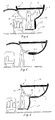
- Fig. 7
- eine am oberen Rand der Beladeöffnung angelenkte faltbare Gepäckklappe und
- Fig. 8
- die Gepäckklappe nach Fig. 7 in Verbindung mit einer Arbeitsplattform.
- Fig. 1 zeigt einen Schnitt durch einen Flugzeugrumpf, im wesentlichen bestehend aus einer Rumpfstruktur 1 von annähernd kreisförmigem Querschnitt und einer den Kabinenboden tragenden Fußbodenstruktur 2, wobei diese in seitlichen Verbindungsbereichen 3,4 an der Rumpfstruktur 1 angeschlossen ist. Unterhalb der Fußbodenstruktur 2 befindet sich der mit Gepäckstücken beladbare Gepäckraum 5. Die Höhe H der tiefsten Stelle des Rumpfquerschnitts über dem Erdboden B beträgt das 0,4- bis 0,6-fache der Durchschnittskörpergröße einer menschlichen Person. Der im Türbereich des Gepäckraumes 5 geführte Schnitt zeigt die Beladeöffnung 6 und die Gepäckklappe 7, die mittels eines Scharniers 8 mit einer annähernd parallel zur Rumpfachse verlaufenden Schwenkachse mit der Rumpfstruktur 1 verbunden ist. Das Öffnen der Gepäckklappe 7, geschieht durch Schwenken nach außen um das Scharnier 8. Die Beladeöffnung 6 erstreckt sich annähernd von dem im Bild linken Verbindungsbereich 3 nach unten in Umfangsrichtung bis in den Bereich der Rumpfmittelebene. Durch diese Ausbildung der Beladeöffnung 6 kann eine Werkperson 9 auf dem Erdboden B aufrecht stehen, so daß sich sein Oberkörper mit hinreichender Bewegungsfreiheit für die Arme innerhalb des Laderaumes 5 befindet. Infolge der gegenüber der bekannten Gepäckklappe erweiterten Beladeöffnung 6 kann die Werkperson 9 das Gepäck 10 von einem an günstiger Stelle abgestellten Gepäckkarren 11 nehmen und in aufrechter Haltung auf ein Förderband 5a auflegen. Optimale Verhältnisse liegen vor, wenn die Rumpfkontur, wie gezeigt, etwa im Bereich der Gürtellinie der Werkperson 9 verläuft. In der gezeigten Ausgestaltung der Gepäckklappe 7 ergibt sich die günstige Relation zwischen der Rumpfkontur und der Gürtellinie der Werkperson 9 zufällig durch die Höhe H.
- Fig. 2 zeigt eine andere Ausgestaltung der Erfindung, mit den Bezugszeichen 1 bis 6 und 9 bis 11, wobei die mit 12 bezeichnete Gepäckklappe faltbar ausgebildet ist. Die Gepäckklappe 12 ist an der Rumpfstruktur 1 in dem dem Verbindungsbereich 3 gegenüberliegenden Bereich der Beladeöffnung 6 mittels eines Scharnieres 13 angelenkt. Die Faltbarkeit der Gepäckklappe 12 wird durch ein Scharnier 14 mit einer zur Rumpfachse annähernd parallelen Schwenkachse erreicht. Auch hierbei erstreckt sich die Beladeöffnung 6 aus der Nähe des Verbindungsbereiches 3 bis in den Bereich der Rumpfmittelebene, so daß die hier vorliegenden Arbeitsbedingungen im Prinzip mit denen übereinstimmen, wie sie sich aus der Ausgestaltung nach Fig. 1 ergeben. Hierzu trägt bei, daß die Höhe der tiefsten Stelle des Rumpfquerschnitts über dem Erdboden B mit der Höhe H nach Fig. 1 annähernd übereinstimmt. Aufgrund der Faltbarkeit der Gepäckklappe 12 kann diese in geöffnetem Zustand nicht durch Bodenfahrzeuge beschädigt werden. Je nach den geometrischen Verhältnissen des Flugzeuges sind unterschiedliche Ausgestaltungen der Gepäckklappe 7,12 denkbar.
- Figur 3 zeigt eine Ausgestaltung der Erfindung, wobei die tiefste Stelle des Rumpfquerschnitts über dem Erdboden B, verglichen mit den Beispielen nach den Figuren 1 und 2, eine größere Höhe H₁ aufweist. Die hier mit 15 bezeichnete Gepäckklappe besteht aus einem an der Rumpfstruktur 1 angelenkten Anlenkteil 16 und einem in geöffnetem Zustand freien gegenüber dem Anlenkteil 16 schwenkbaren Schließteil 17. Zur Verbindung des Anlenkteils 16 mit der Rumpfstruktur 1 ist ein Scharnier 18 vorgesehen. Die Anlenkung des Schließteils 17 erfolgt über ein Schwenkscharnier 19. Die Schwenkachsen beider Scharniere 18, 19 verlaufen annähernd parallel zur Rumpfachse. Infolge der größeren Höhe H₁ würde ein auf dem Erdboden B stehender Ladearbeiter eine ungünstige Position gegenüber dem Gepäckraum 5 einnehmen. Diesem Nachteil wird dadurch abgeholfen, daß der in geöffnetem Zustand freie Schließteil 17 eine in Beladestellung annähernd horizontal ausgerichtete Arbeitsplattform 20 aufweist. Zur Herstellung optimaler Arbeitsbedingungen ist die Arbeitsplattform 20 gegenüber der Rumpfstruktur 1 so angeordnet, daß die Rumpfkontur wieder etwa im Bereich der Gürtellinie der Werkperson 9 verläuft.
- Figur 4 zeigt eine Ausgestaltung der Erfindung, wobei die Gepäckklappe zweiteilig ausgebildet ist und aus einer Oberstruktur 21 und einer Unterstruktur 22 besteht, die jeweils an der Rumpfstruktur 1 mittels eines oberen Scharniers 23 und eines unteren Scharniers 24 angelenkt sind. Dabei erstreckt sich die Beladeöffnung 6 wieder von dem im Bild linken Verbindungsbereich 3 nach unten in Umfangsrichtung bis in den Bereich der Rumpfmittelebene. Infolge einer aus der Unterstruktur 22 ausklappbaren Arbeitsplattform 25 kann die Werkperson 9 im Prinzip die Gepäckstücke 10 dem Gepäckkarren 11 unter den gleichen Arbeitsbedingungen entnehmen und im Gepäckraum 5 verstauen wie bei der Ausgestaltung nach Fig. 3. Die hier beschriebene Ausgestaltung bietet jedoch den Vorteil, daß der Gepäckraum 5 nach Schließen der Unterstruktur 22 weiter beladbar ist.
- Figur 5 zeigt die Ausgestaltung nach Fig. 4 mit geschlossener Unterstruktur 22. Damit wird die Arbeitsplattform 25 zu einem Teil der Innenwand des Gepäckraumes 5. Hierdurch besteht im Türbereich eine zusätzlich beladbare Fläche des Gepäckraumes 5, so daß dieser weitere Gepäckstücke aufnehmen kann.
- Figur 6 zeigt nun eine andere Ausgestaltung der Erfindung, wobei sich die feste Rumpfstruktur 1 bis über die Rumpfmittelebene M erstreckt, wodurch sich eine kleinere Beladeöffnung 26 ergibt. Dabei ist die mit 27 bezeichnete Gepäckklappe im Fußbodenbereich des Gepäckraumes 5 mittels eines Scharniers 28 an der Rumpfstruktur 1 angelenkt und in ihrem in geöffnetem Zustand freien Ende mit einer ausklappbaren Arbeitsplattform 29 versehen. Dabei ergibt sich im Prinzip die gleiche Arbeitsweise wie bei der Ausgestaltung nach Fig. 5, wobei jedoch von Vorteil ist, daß die Höhe des Rumpfes über dem Erdboden aufgrund der Arbeitsplattform 29 jetzt größer sein darf. Da die Zugänglichkeit des Gepäckraumes für die Werkperson 9 nicht in dem Maße gegeben ist wie in den Ausgestaltungen nach den Fign. 1 bis 4, ist die Anwendung einer flugzeugseitigen Ladehilfe, beispielsweise eines Förderbandes, sinnvoll. Ist der Beladevorgang beendet, wird die Arbeitsplattform 29 nach oben geklappt und in ihrer Ruheposition gesichert. Danach wird die Gepäckklappe 27 geschlossen und verriegelt. Auch bei dieser Ausgestaltung besteht im Türbereich eine zusätzlich beladbare Fläche des Gepäckraumes 5, so daß dieser weitere Gepäckstücke aufnehmen kann.
- Fig. 7 zeigt einen Schnitt durch einen Flugzeugrumpf, im wesentlichen bestehend aus einer Rumpfstruktur 1 von annähernd kreisförmigem Querschnitt und einer den Kabinenboden tragenden Fußbodenstruktur 2, wobei diese seitliche Verbindungsbereiche 3,4 mit der Rumpfstruktur 1 aufweist. Unterhalb der Fußbodenstruktur 2 befindet sich der mit Gepäckstücken beladbare Gepäckraum 5. Die Höhe H der tiefsten Stelle des Rumpfquerschnitts über dem Erdboden B beträgt das 0,4- bis 0,6-fache der Durchschnittskörpergröße einer menschlichen Person. Der im Türbereich des Gepäckraumes 5 geführte Schnitt zeigt die Beladeöffnung 6 mit der faltbar ausgebildeten Gepäckklappe 7a. Diese ist über ein Scharnier 8 mit einer annähernd parallel zur Rumpfachse verlaufenden Schwenkachse mit der Rumpfstruktur 1 verbunden und besteht aus einem Anlenkteil 7b, und einem damit über ein Scharnier 7c verbundenen Schließteil 7d. Das Öffnen der Gepäckklappe 7, geschieht durch Schwenken nach außen um das Scharnier 8 und gleichzeitiges Einschwenken des Schließteils 7c zum Anlenkteil 7a hin um das Scharnier 7b. Die Beladeöffnung 6 erstreckt sich annähernd von dem im Bild linken Verbindungsbereich 3 nach unten in Umfangsrichtung bis über die Rumpfmittelebene hinaus. Durch diese Ausbildung der Beladeöffnung 6 kann eine Werkperson 9 auf dem Erdboden B aufrecht stehen, so daß sich ihr Oberkörper mit hinreichender Bewegungsfreiheit für die Arme innerhalb des Laderaumes 5 befindet. Infolge der erweiterten Beladeöffnung 6 kann der Gepäckkarren 11 an günstiger Stelle positioniert werden, so daß das Gepäck 10 von der Werkperson 9 in aufrechter Haltung auf ein Förderband 5a gelegt werden kann.
- Figur 8 zeigt eine weitere erfindungsgemäße Lösung, wobei die Arbeitsgänge, wie in Verbindung mit Fig. 4 beschrieben, ablaufen. Hierbei ist die Gepäckklappe 30 wieder faltbar ausgebildet und in der Nähe des Verbindungsbereiches 3 über ein Scharnier 31 mit der Rumpfstruktur verbunden. Die Beladeöffnung 32 erstreckt sich vom Scharnier 31 bis über die Rumpfmittelebene hinaus. Eine Arbeitsplattform 33 ist über eine Trageinrichtung 34 und ein Scharnier 35 mit der Rumpfstruktur 1 verbunden. Die Arbeitsplattform 33 mit der Trageinrichtung 34 ist in Arbeitsposition dargestellt. Bei Nichtbenutzung, also unter anderem während des Fluges, ist die Arbeitsplattform 33 mit der Trageinrichtung 34 in der strich-punktiert dargestellten Stauposition 36 verriegelt. Soll der Gepäckraum 5 eines gelandeten Flugzeuges entladen werden, so wird zunächst die Gepäckklappe 30 geöffnet und in die gezeigte offene Stellung gebracht. Dann wird die Arbeitsplattform 33 durch die Beladeöffnung 32 nach unten geklappt, durch Entfalten in die gezeigte Arbeitsposition gebracht und darin verriegelt. Infolge der faltbaren Ausbildung der Gepäckklappe befindet sich diese in ihrer Beladeposition außerhalb des Einflußbereiches von Bodengeräten, so daß sie weitgehend gegen Beschädigung geschützt ist.
- Zum Schließen und Verriegeln der Gepäckklappe sind alle bekannten Lösungsprinzipien anwendbar. Auch um die Gepäckklappe mehr oder weniger in den Festigkeitsverband des Rumpfes einzubeziehen, sind alle bekannten Lösungen verwendbar.
Claims (10)
- Gepäckklappe zum Schließen einer Beladeöffnung für ein Verkehrsflugzeug mit etwa 80 bis 150 Sitzen, wobei der Gepäckraum unterhalb des Kabinenbodens angeordnet ist,
gekennzeichnet, durch die Kombination folgender Merkmalea. die Gepäckklappe (7,7a,12,15,30) ist nach außen schwenkbar ausgebildet,b. die Beladeöffnung (6) erstreckt sich von dem Verbindungsbereich (3,4) des Kabinenbodens mit der Rumpfstruktur (1) abwärts in Umfangsrichtung bis etwa in den Bereich der Rumpfmittelebene (M). - Gepäckklappe nach Anspruch 1,
dadurch gekennzeichnet, daß sich die Beladeöffnung (6) von dem Verbindungsbereich (3,4) in Umfangsrichtung bis hinter die Rumpfmittelebene (M) erstreckt. - Gepäckklappe nach Anspruch 1 oder 2,
dadurch gekennzeichnet, daß sich die Beladeöffnung (6) von dem Verbindungsbereich (3,4) in Umfangsrichtung bis vor die Rumpfmittelebene (M) erstreckt. - Gepäckklappe nach einem der Ansprüche 1 bis 3,
dadurch gekennzeichnet, daß die Gepäckklappe (7,7a,12,15,30) im oberen Kantenbereich der Beladeöffnung (6) an der Rumpfstruktur (1) angelenkt ist. - Gepäckklappe nach einem der Ansprüche 1 bis 3,
dadurch gekennzeichnet, daß die Gepäckklappe (7,7a,12,15,30) im unteren Kantenbereich der Beladeöffnung (6) an der Rumpfstruktur (1) angelenkt ist. - Gepäckklappe nach einem der Ansprüche 1 bis 5,
dadurch gekennzeichnet, daß die Gepäckklappe (7,7a,12,15,30) faltbar ausgebildet ist und aus einem Anlenkteil (16) und einem Schließteil (17) besteht. - Gepäckklappe nach Anspruch 6,
dadurch gekennzeichnet, daß der in geöffnetem Zustand freie Schließteil (17) der Gepäckklappe (7,7a,12, 15,30) eine in Beladestellung annähernd horizontal ausgerichtete Arbeitsplattform (20,33) aufweist. - Gepäckklappe nach einem der Ansprüche 1 bis 7,
dadurch gekennzeichnet, daß der untere Kantenbereich der Beladeöffnung (6,26,32) mit einer ausklappbaren Arbeitsplattform (33) versehen ist. - Gepäckklappe nach einem der Ansprüche 1 bis 8,
dadurch gekennzeichnet, daß die Arbeitsplattform (33) über eine Trageinrichtung (34) und ein Scharnier (35) mit der Rumpfstruktur (1) verbunden ist. - Gepäckklappe nach einem der Ansprüche 1 bis 9,
dadurch gekennzeichnet, daß die Gepäckklappe zweiteilig ausgebildet ist und aus einer Oberstruktur (21) und einer Unterstruktur (22) bsteht.
Applications Claiming Priority (4)
| Application Number | Priority Date | Filing Date | Title |
|---|---|---|---|
| DE4134499 | 1991-10-18 | ||
| DE4134499A DE4134499C2 (de) | 1991-10-18 | 1991-10-18 | Klappe zum Schließen einer Beladeöffnung |
| DE4233047 | 1992-10-01 | ||
| DE4233047A DE4233047C2 (de) | 1991-10-18 | 1992-10-01 | Klappe zum Schließen einer Beladeöffnung |
Publications (2)
| Publication Number | Publication Date |
|---|---|
| EP0537699A1 true EP0537699A1 (de) | 1993-04-21 |
| EP0537699B1 EP0537699B1 (de) | 1997-03-12 |
Family
ID=25908332
Family Applications (1)
| Application Number | Title | Priority Date | Filing Date |
|---|---|---|---|
| EP92117521A Expired - Lifetime EP0537699B1 (de) | 1991-10-18 | 1992-10-14 | Gepäckklappe für ein Flugzeug |
Country Status (4)
| Country | Link |
|---|---|
| US (1) | US5335880A (de) |
| EP (1) | EP0537699B1 (de) |
| DE (2) | DE4134499C2 (de) |
| ES (1) | ES2099781T3 (de) |
Cited By (3)
| Publication number | Priority date | Publication date | Assignee | Title |
|---|---|---|---|---|
| DE102008005595B4 (de) * | 2008-01-22 | 2013-11-14 | Airbus Operations Gmbh | Frachtraumtür in einer Rumpfzelle eines Flugzeugs |
| US20140048649A1 (en) * | 2012-08-14 | 2014-02-20 | Intertechnique | Utilization for aircraft airstair space and fuel cell system integration |
| FR3020340A1 (fr) * | 2014-04-29 | 2015-10-30 | Airbus Operations Sas | Aeronef comportant deux portes de train d'atterrissage et un systeme de manœuvre destine a manœuvrer lesdites portes |
Families Citing this family (20)
| Publication number | Priority date | Publication date | Assignee | Title |
|---|---|---|---|---|
| US5553615A (en) * | 1994-01-31 | 1996-09-10 | Minnesota Mining And Manufacturing Company | Method and apparatus for noninvasive prediction of hematocrit |
| US6182598B1 (en) * | 1999-03-09 | 2001-02-06 | Horacio E. Bozzo | Stair assembly for marine craft |
| US6616100B2 (en) | 2001-10-02 | 2003-09-09 | The Boeing Company | Cargo loading means for short body airplanes |
| US7014144B2 (en) * | 2003-07-22 | 2006-03-21 | Honeywell International, Inc. | Dual action inlet door and method for use thereof |
| FR2872778B1 (fr) * | 2004-07-09 | 2007-10-12 | Airbus France Sas | Porte pour aeronef, et aeronef muni d'au moins une telle porte |
| ES2281227B1 (es) * | 2004-12-31 | 2008-09-16 | Airbus España, S.L. | Un mecanismo de accionamiento de una trampa, particularmente para un tren de aterrizaje de un avion. |
| GB0525692D0 (en) * | 2005-12-16 | 2006-01-25 | Airbus Uk Ltd | Cargo loading apparatus |
| US8215581B1 (en) * | 2009-07-08 | 2012-07-10 | The Boeing Company | Advanced cargo ramp |
| US10314285B1 (en) * | 2012-03-20 | 2019-06-11 | The Boeing Company | Platform and guide panel for aircraft cabin egress |
| CN103600834B (zh) * | 2013-11-27 | 2016-08-03 | 中国航空工业集团公司西安飞机设计研究所 | 一种可实现大角度翻转的飞机舱门快卸机构 |
| EP2889213A1 (de) * | 2013-12-30 | 2015-07-01 | Airbus Operations S.L. | Entenflügler mit Heckbeladung |
| EP3050794B1 (de) * | 2015-01-28 | 2017-05-10 | AIRBUS HELICOPTERS DEUTSCHLAND GmbH | Flugzeug mit nach innen faltbarer hecktür |
| JP2018059263A (ja) * | 2015-02-23 | 2018-04-12 | 株式会社小松製作所 | 作業車両及びその制御方法 |
| DE102017122599B4 (de) * | 2017-09-28 | 2020-03-19 | Airbus Operations Gmbh | Flugzeug mit einem rumpf, gepäckhalterung für ein flugzeug und luftfrachtcontainer mit einer gepäckhalterung |
| ES2938710T3 (es) * | 2018-03-28 | 2023-04-14 | Hartwell Corp | Conjunto de puerta que comprende una bisagra con dos pasadores |
| US20220162893A1 (en) | 2019-03-20 | 2022-05-26 | Scandinavian Cargoloading Technologies Ab | Cargo door operating method and device |
| DE102020118478B4 (de) | 2020-07-14 | 2024-02-08 | Lufthansa Technik Aktiengesellschaft | Frachtbrücke für Verkehrsflugzeug und Verkehrsflugzeug |
| EP3998191A1 (de) * | 2021-02-19 | 2022-05-18 | Lilium eAircraft GmbH | Passagierflugzeug |
| RU205293U1 (ru) * | 2021-03-30 | 2021-07-07 | Акционерное общество "Национальный центр вертолетостроения им. М.Л. Миля и Н.И. Камова" (АО "НЦВ Миль и Камов") | Транспортная кабина с открывающимися створками |
| WO2024015482A1 (en) * | 2022-07-13 | 2024-01-18 | Supernal, Llc | Methods, systems, and devices for a door for a vehicle |
Citations (2)
| Publication number | Priority date | Publication date | Assignee | Title |
|---|---|---|---|---|
| FR2110343A1 (de) * | 1970-10-10 | 1972-06-02 | British Aircraft Corp Ltd | |
| US4453684A (en) * | 1981-12-09 | 1984-06-12 | Omac, Inc. | Step operated locking mechanism for aircraft lower door |
Family Cites Families (13)
| Publication number | Priority date | Publication date | Assignee | Title |
|---|---|---|---|---|
| CA815921A (en) * | 1969-06-24 | William G. Spence | Aircraft passenger door | |
| GB603203A (en) * | 1946-11-26 | 1948-06-10 | English Electric Co Ltd | Improvements relating to aircraft doors |
| GB913005A (en) * | 1960-10-24 | 1962-12-12 | Blackburn Aircraft Ltd | Improvements in and relating to doors for freight carrying aircraft |
| US3174717A (en) * | 1961-12-07 | 1965-03-23 | Grinnell Corp | Ratchet actuated fast-opening, slow-closing valve |
| FR1352138A (fr) * | 1962-09-25 | 1964-02-14 | Aviation Louis Breguet Sa | Porte de soute pour fuselage d'aéronefs |
| DE1225503B (de) * | 1964-11-26 | 1966-09-22 | Dornier Werke Gmbh | Verschlusseinrichtung fuer den Boden eines Hubtriebwerksschachtes |
| GB1362949A (en) * | 1970-10-06 | 1974-08-07 | Hawker Siddeley Aviation Ltd | Aircraft |
| US4446524A (en) * | 1978-01-18 | 1984-05-01 | Messerschmitt-Boelkow-Blohm Gesellschaft Mit Beschraenkter Haftung | Apparatus for loading and unloading an aircraft |
| US4440364A (en) * | 1981-09-08 | 1984-04-03 | Cone Steven S | Retractable aircraft step |
| EP0124521B1 (de) * | 1982-10-29 | 1988-03-30 | The Boeing Company | Klappfrachttür für ein flugzeug |
| DE3608735A1 (de) * | 1986-03-15 | 1987-09-24 | Messerschmitt Boelkow Blohm | Frachttor mit gewichtsausgleichsmechanismus |
| DE3806688A1 (de) * | 1988-03-02 | 1989-09-14 | Messerschmitt Boelkow Blohm | Oeffnungsvorrichtung fuer ein flugzeugfrachttor |
| SE458520B (sv) * | 1988-03-21 | 1989-04-10 | Scandinavian Bellyloading | Saekerhetsanordning i lastutrymmet i ett flygplan |
-
1991
- 1991-10-18 DE DE4134499A patent/DE4134499C2/de not_active Expired - Lifetime
-
1992
- 1992-10-01 DE DE4233047A patent/DE4233047C2/de not_active Expired - Lifetime
- 1992-10-14 EP EP92117521A patent/EP0537699B1/de not_active Expired - Lifetime
- 1992-10-14 ES ES92117521T patent/ES2099781T3/es not_active Expired - Lifetime
- 1992-10-16 US US07/962,147 patent/US5335880A/en not_active Expired - Lifetime
Patent Citations (2)
| Publication number | Priority date | Publication date | Assignee | Title |
|---|---|---|---|---|
| FR2110343A1 (de) * | 1970-10-10 | 1972-06-02 | British Aircraft Corp Ltd | |
| US4453684A (en) * | 1981-12-09 | 1984-06-12 | Omac, Inc. | Step operated locking mechanism for aircraft lower door |
Cited By (4)
| Publication number | Priority date | Publication date | Assignee | Title |
|---|---|---|---|---|
| DE102008005595B4 (de) * | 2008-01-22 | 2013-11-14 | Airbus Operations Gmbh | Frachtraumtür in einer Rumpfzelle eines Flugzeugs |
| US20140048649A1 (en) * | 2012-08-14 | 2014-02-20 | Intertechnique | Utilization for aircraft airstair space and fuel cell system integration |
| FR3020340A1 (fr) * | 2014-04-29 | 2015-10-30 | Airbus Operations Sas | Aeronef comportant deux portes de train d'atterrissage et un systeme de manœuvre destine a manœuvrer lesdites portes |
| US9701400B2 (en) | 2014-04-29 | 2017-07-11 | Airbus Operations (Sas) | Aircraft comprising two landing gear doors and a maneuvering system intended to maneuver said doors |
Also Published As
| Publication number | Publication date |
|---|---|
| DE4134499A1 (de) | 1993-04-22 |
| US5335880A (en) | 1994-08-09 |
| DE4233047A1 (de) | 1994-04-07 |
| ES2099781T3 (es) | 1997-06-01 |
| DE4134499C2 (de) | 1994-09-22 |
| DE4233047C2 (de) | 1995-11-30 |
| EP0537699B1 (de) | 1997-03-12 |
Similar Documents
| Publication | Publication Date | Title |
|---|---|---|
| EP0537699B1 (de) | Gepäckklappe für ein Flugzeug | |
| EP0268749B1 (de) | Fahrzeugsitz | |
| DE10159815B4 (de) | Doppelklappbare Kraftfahrzeugheckklappe | |
| EP1625053B1 (de) | Militärisches kraftfahrzeug zum mannschaftstransport | |
| DE60128199T2 (de) | Lieferwagen | |
| DE102015104589B4 (de) | Drehbare und verstaubare Hutablageanordnung für ein Kraftfahrzeug | |
| DE2228395B2 (de) | Bordeigenes Frachtbe- und -Entladegerät für Flugzeuge | |
| DE60108592T2 (de) | Ein- und Aussteigvorrichtung eines Flugzeuges und Flügelflugzeug mit einer solchen Einrichtung | |
| DE60104043T2 (de) | Flugzeugtür und damit ausgerüstetes Flugzeug | |
| DE102006048998A1 (de) | Teleskopartiges Gepäckfach | |
| DE102005011680B4 (de) | Heckklappe für ein Fahrzeug mit zusätzlichem Ladegutträger | |
| EP3495288A1 (de) | Container für den transport eines fahrzeugs | |
| WO2002014107A1 (de) | System zur unterbringung von ladegut in einem fahrzeug | |
| EP3741597A1 (de) | Modulare heckbaugruppe für ein kraftfahrzeug | |
| DE4425869C2 (de) | Überkopf-Gepäckablage, insbesondere für ein Passagierflugzeug | |
| DE10204892B4 (de) | Fördereinrichtung für den Vertikaltransport von Verpflegungsbehältnissen in Verkehrsflugzeugen | |
| WO2000009060A1 (de) | Fahrzeug mit einem zur aufnahme eines rollstuhles gegenüber dem fahrzeugboden abgesenkten ladeboden | |
| DE102016210856A1 (de) | Erweiterbarer Cargostauraum, Transportmittelabschnitt, Transportmittel und Verfahren zum Betreiben eines Cargostauraums, eines Transportmittelabschnitts oder eines Transportmittels | |
| DE102017210939B4 (de) | Ablageeinrichtung zur Anordnung in einem Kraftfahrzeug und Kraftfahrzeug | |
| DE19745152C1 (de) | Leicht verstaubare Hutablage | |
| DE102015120059B4 (de) | Kühlfahrzeuganordnung | |
| DE102019132823A1 (de) | Flugzeug zum Fracht- und Passagiertransport, Frachtcontainer und Verfahren zum Beladen eines Flugzeugs | |
| DE60006943T2 (de) | Flughafenfahrzeug zur aufnahme von fluggästen und lasten | |
| DE102008005595B4 (de) | Frachtraumtür in einer Rumpfzelle eines Flugzeugs | |
| DE102017217088A1 (de) | Seitliche Begrenzung für eine Ladeflächenverlängerung |
Legal Events
| Date | Code | Title | Description |
|---|---|---|---|
| PUAI | Public reference made under article 153(3) epc to a published international application that has entered the european phase |
Free format text: ORIGINAL CODE: 0009012 |
|
| AK | Designated contracting states |
Kind code of ref document: A1 Designated state(s): ES FR GB IT NL SE |
|
| 17P | Request for examination filed |
Effective date: 19930528 |
|
| 17Q | First examination report despatched |
Effective date: 19940524 |
|
| RAP1 | Party data changed (applicant data changed or rights of an application transferred) |
Owner name: DAIMLER-BENZ AEROSPACE AIRBUS GESELLSCHAFT MIT BES |
|
| GRAG | Despatch of communication of intention to grant |
Free format text: ORIGINAL CODE: EPIDOS AGRA |
|
| GRAH | Despatch of communication of intention to grant a patent |
Free format text: ORIGINAL CODE: EPIDOS IGRA |
|
| GRAH | Despatch of communication of intention to grant a patent |
Free format text: ORIGINAL CODE: EPIDOS IGRA |
|
| GRAA | (expected) grant |
Free format text: ORIGINAL CODE: 0009210 |
|
| AK | Designated contracting states |
Kind code of ref document: B1 Designated state(s): ES FR GB IT NL SE |
|
| REG | Reference to a national code |
Ref country code: ES Ref legal event code: FG2A Ref document number: 2099781 Country of ref document: ES Kind code of ref document: T3 |
|
| ET | Fr: translation filed | ||
| GBT | Gb: translation of ep patent filed (gb section 77(6)(a)/1977) |
Effective date: 19970522 |
|
| PLBE | No opposition filed within time limit |
Free format text: ORIGINAL CODE: 0009261 |
|
| STAA | Information on the status of an ep patent application or granted ep patent |
Free format text: STATUS: NO OPPOSITION FILED WITHIN TIME LIMIT |
|
| 26N | No opposition filed | ||
| REG | Reference to a national code |
Ref country code: FR Ref legal event code: CD |
|
| REG | Reference to a national code |
Ref country code: GB Ref legal event code: IF02 |
|
| PGFP | Annual fee paid to national office [announced via postgrant information from national office to epo] |
Ref country code: GB Payment date: 20101021 Year of fee payment: 19 Ref country code: IT Payment date: 20101026 Year of fee payment: 19 |
|
| PGFP | Annual fee paid to national office [announced via postgrant information from national office to epo] |
Ref country code: NL Payment date: 20111025 Year of fee payment: 20 Ref country code: ES Payment date: 20111026 Year of fee payment: 20 Ref country code: SE Payment date: 20111021 Year of fee payment: 20 Ref country code: FR Payment date: 20111103 Year of fee payment: 20 |
|
| REG | Reference to a national code |
Ref country code: NL Ref legal event code: V4 Effective date: 20121014 |
|
| REG | Reference to a national code |
Ref country code: GB Ref legal event code: PE20 Expiry date: 20121013 |
|
| REG | Reference to a national code |
Ref country code: SE Ref legal event code: EUG |
|
| PG25 | Lapsed in a contracting state [announced via postgrant information from national office to epo] |
Ref country code: GB Free format text: LAPSE BECAUSE OF EXPIRATION OF PROTECTION Effective date: 20121013 |
|
| REG | Reference to a national code |
Ref country code: ES Ref legal event code: FD2A Effective date: 20130725 |
|
| PG25 | Lapsed in a contracting state [announced via postgrant information from national office to epo] |
Ref country code: ES Free format text: LAPSE BECAUSE OF EXPIRATION OF PROTECTION Effective date: 20121015 |