EP0537311B1 - Dünnschichtverdampfer aus korrosionsbeständigem material - Google Patents
Dünnschichtverdampfer aus korrosionsbeständigem material Download PDFInfo
- Publication number
- EP0537311B1 EP0537311B1 EP92908986A EP92908986A EP0537311B1 EP 0537311 B1 EP0537311 B1 EP 0537311B1 EP 92908986 A EP92908986 A EP 92908986A EP 92908986 A EP92908986 A EP 92908986A EP 0537311 B1 EP0537311 B1 EP 0537311B1
- Authority
- EP
- European Patent Office
- Prior art keywords
- rotor
- tube
- film evaporator
- evaporator according
- ring
- Prior art date
- Legal status (The legal status is an assumption and is not a legal conclusion. Google has not performed a legal analysis and makes no representation as to the accuracy of the status listed.)
- Expired - Lifetime
Links
Images


Classifications
-
- B—PERFORMING OPERATIONS; TRANSPORTING
- B01—PHYSICAL OR CHEMICAL PROCESSES OR APPARATUS IN GENERAL
- B01D—SEPARATION
- B01D1/00—Evaporating
- B01D1/22—Evaporating by bringing a thin layer of the liquid into contact with a heated surface
- B01D1/222—In rotating vessels; vessels with movable parts
- B01D1/223—In rotating vessels; vessels with movable parts containing a rotor
- B01D1/225—In rotating vessels; vessels with movable parts containing a rotor with blades or scrapers
-
- F—MECHANICAL ENGINEERING; LIGHTING; HEATING; WEAPONS; BLASTING
- F28—HEAT EXCHANGE IN GENERAL
- F28F—DETAILS OF HEAT-EXCHANGE AND HEAT-TRANSFER APPARATUS, OF GENERAL APPLICATION
- F28F21/00—Constructions of heat-exchange apparatus characterised by the selection of particular materials
- F28F21/02—Constructions of heat-exchange apparatus characterised by the selection of particular materials of carbon, e.g. graphite
-
- Y—GENERAL TAGGING OF NEW TECHNOLOGICAL DEVELOPMENTS; GENERAL TAGGING OF CROSS-SECTIONAL TECHNOLOGIES SPANNING OVER SEVERAL SECTIONS OF THE IPC; TECHNICAL SUBJECTS COVERED BY FORMER USPC CROSS-REFERENCE ART COLLECTIONS [XRACs] AND DIGESTS
- Y10—TECHNICAL SUBJECTS COVERED BY FORMER USPC
- Y10S—TECHNICAL SUBJECTS COVERED BY FORMER USPC CROSS-REFERENCE ART COLLECTIONS [XRACs] AND DIGESTS
- Y10S159/00—Concentrating evaporators
- Y10S159/15—Special material
-
- Y—GENERAL TAGGING OF NEW TECHNOLOGICAL DEVELOPMENTS; GENERAL TAGGING OF CROSS-SECTIONAL TECHNOLOGIES SPANNING OVER SEVERAL SECTIONS OF THE IPC; TECHNICAL SUBJECTS COVERED BY FORMER USPC CROSS-REFERENCE ART COLLECTIONS [XRACs] AND DIGESTS
- Y10—TECHNICAL SUBJECTS COVERED BY FORMER USPC
- Y10S—TECHNICAL SUBJECTS COVERED BY FORMER USPC CROSS-REFERENCE ART COLLECTIONS [XRACs] AND DIGESTS
- Y10S165/00—Heat exchange
- Y10S165/905—Materials of manufacture
Definitions
- the invention relates to a thin-film evaporator with a heatable tubular evaporator body, in the interior of which the product acts, a rotor which is provided with essentially radially oriented vanes and can be driven from the outside is arranged.
- Thin-film evaporators of the aforementioned type are used to concentrate viscous, temperature-sensitive and / or deposit-forming substances. They are all based on the principle of creating a thin product layer inside a heated cylinder or cone with the help of a rotating rotor, so that the heat introduced via the cylinder wall leads to evaporation of the liquid, with the vapor only passing a short way through the product must cover.
- the rotor has rigid blades that have a small gap of a few millimeters to the heated wall or but it is equipped with movable wiper blades so that the product running over the heated walls of the evaporator body can be kept in a thin product film.
- the corrosion problems cannot be solved with metallic materials, especially since the evaporator body must also be designed as a pressure vessel.
- enamel coatings can only solve the corrosion problem in special cases, especially since it is practically impossible for larger units to carry out the required mechanical processing.
- the invention has for its object to design a thin-film evaporator of the type mentioned in such a way that the evaporator body has high corrosion resistance with good thermal conductivity.
- the evaporator body is formed by at least one thick-walled tube made of graphite, that several substantially axially extending bores are arranged in the tube wall, and that the mouths of the bores at the tube ends each open into an annular channel, the is connected to a connection piece for a heating medium.
- the ring channel is formed as an open groove in each case in a clamping ring which can be placed against the tube on the end face the tube is kept sealed between two end clamping rings via spring-loaded clamping anchors and that the clamping rings are each provided with the connecting piece for the heating medium, which opens into the associated groove.
- the clamping rings are made of metal, preferably steel, the inner surfaces coming into contact with the product being coated or lined with corrosion-resistant materials. Corrosion resistance can thus be achieved in these areas as well, taking advantage of the fact that there are less exacting requirements in the area of the clamping rings which lie outside the working area of the rotor blades.
- the evaporator body made of graphite retains its simple geometric shape, whereby the tension anchors, including the required tension springs, are designed to withstand the pressure exerted by the heating medium, i.e. to hold the tension rings close to the end faces of the graphite tube in the system .
- the upper clamping ring has an inlet nozzle for the product to be treated and a discharge nozzle for the vapors as the top ring. This part, including the nozzle, is thus to be produced as a self-contained component.
- the lower clamping ring is provided as an outlet ring with an inwardly projecting circumferential conical collar.
- the rotor with its part lying in the interior of the evaporator body essentially consists of a core tube made of graphite, to which the blades made of graphite are attached.
- the wings are formed by at least three thin plates which are curved in the shape of a shell and lie against one another with their longitudinal edges and are each fastened to the core tube in the apex region by means of tensioning screws.
- the core tube made of graphite and the wings are made of a carbon fiber reinforced material, for example a carbon fiber reinforced plastic, so that the thin curved plates forming the wings lie against each other under tension with their edges and stiffen each other.
- the thick-walled tube forming the evaporator body and / or the core tube of the rotor and / or the blades of the rotor consist of a carbon fiber reinforced material.
- the tube of the evaporator body is made of graphite
- the rotor is made of a carbon fiber reinforced material, for example a carbon fiber reinforced plastic.
- the advantage is that the rotor with its components, including the core tube, can be made from thin-walled elements that have high strength. This is particularly interesting if, instead of rigid blades, the rotor is provided with movable wiper blades.
- the term graphite in the sense of the present invention relates to fine-grained, porous electrographite bodies which are made corrosion-resistant, temperature-resistant and pressure-resistant by impregnation with high-molecular synthetic resins.
- the thin-film evaporator shown in FIG. 1 essentially consists of an evaporator body 1 which has a thick-walled tube made of graphite, the structure of which will be described in more detail with reference to FIG. 2.
- the thick-walled tube 2 is pressed against the end faces of the thick-walled tube 2 by a lower tension ring 4 and an upper tension ring 3 with the aid of a plurality of tension anchors 5 uniformly distributed over the circumference.
- the upper clamping ring 3 is designed as a head ring and is provided in its area directly adjacent to the pipe 2 with a connecting piece 6 for the inlet of a heating medium.
- the top ring is also provided with an inlet nozzle 7 for the product to be treated and a discharge nozzle 8 for withdrawing the vapors produced by the evaporation process.
- the clamping ring 4 is in turn provided with a connecting piece 9 through which the heating medium is drawn off.
- the head ring 3 is adjoined above by a housing 10, in which the bearing and the seal for the shaft of the rotor arranged in the thin-film evaporator pass is.
- the drive motor 11 is supported on the housing 10 via a shaft protection tube 12.
- the entire arrangement is supported on the head ring 3 on a support flange 13 and releasably connected to this.
- the concentrated product emerges from the outlet opening formed by the outlet ring 4.
- the tube 2 has a relatively thick wall and is provided with a plurality of axially parallel bores 14 in its wall.
- the bores 14 each open into a groove 15 in the head ring 3 and a groove 16 in the outlet ring 4, which form an annular channel and into which the connecting pieces 6 and 9 open for the heating medium.
- the head ring 3 and the outlet ring 4 are tightly clamped via the tie rods 5 with the interposition of seals 17 with the pipe 2, the thermal expansion of the pipe 2 being absorbed by a prestressed spring assembly 18.
- Head ring 3 and outlet ring 4 are provided with a corrosion-resistant coating 3 ', 4' on their surface that comes into contact with the product.
- the rotor 19, which is only shown in a half-section, is arranged in the interior and is connected at its upper end to a connecting shaft 20 with the drive motor 11.
- the essentially tubular rotor the structure of which will be described with reference to FIGS. 3, 4 and 5, is provided with blades 21.
- the wings 21 cover, as shown in FIG. 2, only the area of the tube 2.
- the rotor 19 is closed at the top with a feed ring 22 which is delimited by an upper and lower edge web 23, so that here forms an annular space 24 into which the inlet port 7 for the product to be treated opens, so that it can enter in the form of a thin layer in the tube 2 and thus in the effective area of the blades 21 of the rotor.
- the vapors formed are drawn off through the outlet 8, which, depending on the method, also creates a vacuum in the interior of the thin-film evaporator serves, deducted.
- the rotor is shown completely in a side view.
- This consists essentially of a core tube 25, on which the wings 21 are placed in the manner described in more detail below.
- the feed ring 22 closes off the area occupied by the wings 21 at the top.
- the core tube 25 is connected to a drive shaft 26 which is connected to the drive motor 11 and which is made of steel in the usual way, since this area of the rotor is already arranged above the housing 10 containing the seals.
- the core tube 25 is made of graphite or a carbon fiber reinforced material.
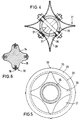
- Fig. 4 shows the section IV-IV in Fig. 3 on a larger scale.
- the core tube 25 is provided over its length with a plurality of intersecting bores through which clamping screws 27 can then be inserted.
- the outer ends of the clamping screws are shown schematically in Fig. 3.
- the blades 21 of the rotor are formed by four shell-shaped, thin plates 28 which lie against one another with their longitudinal edges, the tensioning screws 27 pressing the plates against the core tube 25 in the apex region 29.
- approximately star-shaped plates 30 are provided at both ends, the lower plates of which cover the space between the core tube 25 and the inside of the plate 28.
- the space 31 left free between the edge web 23 serves as a passage channel for the vapors to be drawn off. From supervision according to Fig. 5 can also be seen that the outer edges 32 of the wing 21 projects only slightly beyond the outer edge 33 of the edge webs 23.
- the rotor 19 can also have a solid rotor body 34 made of graphite with an approximately star-shaped cross section, the end edges 35 of which are provided with preferably interchangeable edge elements 36.
- These edge elements which extend over the length of the rotor body 34 and consist of one or more parts placed against one another, are likewise made of a corrosion-resistant material, for example a carbon fiber-reinforced material.
- the edge elements 36 can be rigid or connected to the rotor body 34 as movable wiper blades.
Landscapes
- Engineering & Computer Science (AREA)
- Chemical & Material Sciences (AREA)
- Chemical Kinetics & Catalysis (AREA)
- Physics & Mathematics (AREA)
- Thermal Sciences (AREA)
- Mechanical Engineering (AREA)
- General Engineering & Computer Science (AREA)
- Vaporization, Distillation, Condensation, Sublimation, And Cold Traps (AREA)
- Organic Low-Molecular-Weight Compounds And Preparation Thereof (AREA)
- Body Structure For Vehicles (AREA)
- Inorganic Compounds Of Heavy Metals (AREA)
Description
- Die Erfindung betrifft einen Dünnschichtverdampfer mit einem beheizbaren rohrförmigen Verdampferkörper, in dessen vom Produkt beaufschlagten Innenraum ein mit im wesentlichen radial ausgerichteten Flügeln versehener, von außen antreibbarer Rotor angeordnet ist. Dünnschichtverdampfer der vorbezeichneten Art werden zur Konzentration viskoser, temperaturempfindlicher und/oder belagbildender Stoffe verwendet. Sie beruhen alle auf dem Prinzip, eine dünne Produktschicht im Inneren eines beheizten Zylinders oder Konus mit Hilfe eines umlaufenden Rotors zu erzeugen, so daß die über die Zylinderwandung eingebrachte Wärme zu einer Verdampfung der Flüssigkeit führt, wobei der Dampf nur einen geringen Weg durch das Produkt zurücklegen muß. Damit ist es möglich, feststoffhaltige Flüssigkeiten auf hohe Feststoffkonzentrationen bis zu 80 Gew.-% Trockensubstanz aufzukonzentrieren. Der Rotor besitzt starre Flügel, die einen geringen Spalt von wenigen Millimetern zur beheizten Wand aufweisen oder aber er ist mit beweglichen Wischerblättern ausgestattet, so daß das über die beheizten Wände des Verdampferkörpers laufende Produkt in einem dünnen Produktfilm gehalten werden kann. Bei der Behandlung von korrosiven Medien, beispielsweise bei der Konzentration von mit Feststoffen beladenen Säuren, lassen sich die Koorosionsprobleme mit metallischen Werkstoffen nicht lösen, zumal der Verdampferkörper auch als Druckbehälter ausgelegt sein muß. Versuche mit Emailbeschichtungen vermögen das Korrosionsproblem nur in Sonderfällen zu lösen, zumal es bei größeren Einheiten praktisch nicht möglich ist, die erforderliche mechanische Bearbeitung durchzuführen.
- Der Erfindung liegt die Aufgabe zugrunde, einen Dünnschichtverdampfer der eingangs bezeichneten Art so zu gestalten, daß der Verdampferkörper eine hohe Korrosionsbeständigkeit bei guter Wärmeleitfähigkeit aufweist.
- Diese Aufgabe wird erfindungsgemäß dadurch gelöst, daß der Verdampferkörper durch wenigstens ein dickwandiges Rohr aus Graphit gebildet wird, daß in der Rohrwandung mehrere im wesentlichen axial verlaufende Bohrungen angeordnet sind, und daß jeweils die Mündungen der Bohrungen an den Rohrenden jeweils in einen Ringkanal ausmünden, der mit einem Anschlußstutzen für ein Heizmedium in Verbindung steht. Überraschend hat sich gezeigt, daß ein derartiger Verdampferkörper aus einem dickwandigen Graphitrohr nicht nur hervorragende Wärmeleiteigenschaften hat, sondern auch ein Durchströmen des Heizmediums bei hohen Drücken ermöglicht. Der Innenraum eines derartigen zylindrischen oder konischen Rohres aus Graphit läßt sich einwandfrei und sehr genau bearbeiten, so daß es möglich ist, mit Hilfe des Rotors den für eine hohe Verdampfungsleistung notwendigen gleichmäßig dünnen Produktfilm auf der Innenwandung des Rohres aufzutragen.
- In vorteilhafter Ausgestaltung der Erfindung ist vorgesehen, daß der Ringkanal jeweils in einem gegen das Rohr stirnseitig anlegbaren Spannring als offene Nut ausgebildet ist, daß das Rohr zwischen zwei endseitigen Spannringen über federbelastete Spannanker abgedichtet gehalten ist und daß die Spannringe jeweils mit dem Anschlußstutzen für das Heizmedium versehen sind, der in die zugehörige Nut ausmündet. Die Spannringe sind hierbei aus Metall, vorzugsweise Stahl, hergestellt, wobei die mit dem Produkt in Berührung kommenden Innenflächen mit korrosionsfesten Materialien beschichtet oder ausgekleidet sind. Damit ist auch in diesen Bereichen eine Korrosionsbeständigkeit zu erzielen, wobei ausgenutzt wird, daß im Bereich der Spannringe, die außerhalb des Arbeitsbereiches der Rotorflügel liegen, geringere Anforderungen an die Genauigkeit bestehen. Durch die Verwendung der Spannanker behält der aus Graphit hergestellte Verdampferkörper seine einfache geometrische Form, wobei die Spannanker einschließlich der erforderlichen Spannfedern so ausgelegt sind, daß sie dem durch das Heizmedium aufgebrachten Druck standhalten, d.h. die Spannringe dicht an den Stirnflächen des Graphitrohres in der Anlage halten.
- In weiterer Ausgestaltung der Erfindung ist vorgesehen, daß der obere Spannring als Kopfring einen Einlaßstutzen für das zu behandelnde Produkt und einen Abzugsstutzen für die Brüden aufweist. Damit ist dieser Teil einschließlich der Stutzen als in sich geschlossenes Bauteil herzustellen.
- In weiterer vorteilhafter Ausgestaltung der Erfindung ist vorgesehen, daß der untere Spannring als Auslaßring mit einem nach innen vorspringenden umlaufenden konischen Kragen versehen ist.
- In weiterer bevorzugter Ausgestaltung der Erfindung ist vorgesehen, daß der Rotor mit seinem im Innenraum des Verdampferkörpers liegenden Teil im wesentlichen aus einem Kernrohr aus Graphit besteht, an dem die aus einem Graphit hergestellten Flügel befestigt sind. Damit ist gewährleistet, daß für den vom Rotor mit seinen Flügeln überstrichenen Verdampferbereich einerseits und für den Rotor selbst gleiche Verfahrensbedingungen eingehalten werden können. Hierbei ist es in weiterer Ausgestaltung zweckmäßig, wenn die Flügel durch wenigstens drei schalenförmig gekrümmte dünne Platten gebildet werden, die mit ihren Längsrändern aneinanderliegen und jeweils im Scheitelbereich mittels Spannschrauben am Kernrohr befestigt sind. Hierbei ist es zweckmäßig, wenn das Kernrohr aus Graphit und die Flügel aus einem kohlefaserverstärkten Material, beispielsweise einem kohlefaserverstärkten Kunststoff hergestellt sind, so daß die die Flügel bildenden dünnen gekrümmten Platten unter Spannung mit ihren Rändern gegeneinanderliegen und sich gegenseitig aussteifen.
- In weiterer Ausgestaltung der Erfindung ist vorgesehen, daß das den Verdampferkörper bildende dickwandige Rohr und/oder das Kernrohr des Rotors und/oder die Flügel des Rotors aus einem kohlefaserverstärkten Material bestehen. Hierbei ist es zweckmäßig Kombinationen vorzunehmen, so daß beispielsweise das Rohr des Verdampferkörpers aus Graphit hergestellt ist, während der Rotor aus einem kohlefaserverstärkten Material, beispielsweise einem kohlefaserverstärkten Kunststoff hergestellt ist. Der Vorteil besteht darin, daß gerade der Rotor mit seinen Bauteilen einschließlich des Kernrohres aus dünnwandigen Elementen hergestellt werden kann, die eine hohe Festigkeit aufweisen. Dies ist besonders dann interessant, wenn anstelle starrer Flügel der Rotor mit beweglichen Wischerblättern versehen ist. Der Begriff Graphit im Sinne der vorliegenden Erfindung betrifft feinkörnige, poröse Elektrographitkörper, die durch eine Imprägnierung mit hochmolekularen Kunstharzen korrosions-, temperaturbeständig und druckfest gemacht werden.
- Die Erfindung wird anhand schematischer Zeichnungen näher erläutert. Es zeigen:
- Fig. 1
- einen Dünnschichtverdampfer in einer Seitenansicht,
- Fig. 2
- einen Teillängsschnitt durch den rohrförmigen Verdampferkörper,
- Fig. 3
- einen Rotor mit starren Flügeln,
- Fig. 4
- einen Schnitt durch den Rotor gem. der Linie IV-IV in Fig. 3,
- Fig. 5
- einen Schnitt durch den Rotor gem. der Linie V-V in Fig. 3,
- Fig. 6
- einen Rotor mit massivem Rotorkörper.
- Der in Fig. 1 dargestellte Dünnschichtverdampfer besteht im wesentlichen aus einem Verdampferkörper 1, der ein dickwandiges Rohr aus Graphit aufweist, das in seinem Aufbau anhand von Fig. 2 näher beschrieben werden wird. Das dickwandige Rohr 2 wird stirnseitig durch einen unteren Spannring 4 und einen oberen Spannring 3 mit Hilfe von mehreren gleichmäßig auf den Umfang verteilten Spannankern 5 gegen die Stirnflächen des dickwandigen Rohres 2 gedrückt.
- Der obere Spannring 3 ist hierbei als Kopfring ausgebildet und in seinem unmittelbar am Rohr 2 anliegenden Bereich mit einem Anschlußstutzen 6 für den Einlaß eines Heizmediums versehen. Der Kopfring ist ferner mit einem Einlaßstutzen 7 für das zu behandelnde Produkt und einem Abzugsstutzen 8 zum Abzug der durch den Verdampfungsvorgang entstehenden Brüden versehen. Der Spannring 4 ist seinerseits mit einem Anschlußstutzen 9 versehen, durch den das Heizmedium abgezogen wird. Der Aufbau des Kopfringes 3 und des Auslaßringes 4 wird anhand der Schnittdarstellung in Fig. 2 noch näher erläutert werden.
- An den Kopfring 3 schließt sich oberhalb ein Gehäuse 10 an, in dem die Lagerung und die Dichtung für die Welle des im Dünnschichtverdampfer angeordneten Rotors hindurchgeführt ist. Der Antriebsmotor 11 stützt sich über einen Wellenschutzrohr 12 auf dem Gehäuse 10 ab. Die gesamte Anordnung ist über den Kopfring 3 auf einem Stützflansch 13 abgestützt und mit diesem lösbar verbunden. Das aufkonzentrierte Produkt tritt aus der durch den Auslaßring 4 gebildeten Austrittsöffnung aus.
- Wie aus dem in Fig. 2 wiedergegebenen vertikalen Teillängsschnitt durch den Verdampferkörper 1 ersichtlich, ist das Rohr 2 verhältnismäßig dickwandig ausgebildet und in seiner Wandung mit einer Vielzahl von achsparallelen Bohrungen 14 versehen. Die Bohrungen 14 münden stirnseitig jeweils in eine Nut 15 im Kopfring 3 und eine Nut 16 im Auslaßring 4, die einen Ringkanal bilden und in die die Anschlußstutzen 6 und 9 für das Heizmedium münden. Der Kopfring 3 und der Auslaßring 4 sind über die Zuganker 5 unter Zwischenlage von Dichtungen 17 mit dem Rohr 2 dicht verspannt, wobei die Wärmedehnung des Rohres 2 über ein vorgespanntes Federpaket 18 aufgenommen wird. Kopfring 3 und Auslaßring 4 sind auf ihrer mit dem Produkt in Berührung kommenden Fläche mit einer korrosionsbeständigen Beschichtung 3', 4' versehen.
- Im Innenraum ist der nur in einem Halbschnitt dargestellte Rotor 19 angeordnet, der an seinem oberen Ende mit einer Anschlußwelle 20 mit dem Antriebsmotor 11 in Verbindung steht. Der im wesentlichen rohrförmig ausgebildete Rotor, der in seinem Aufbau noch anhand der Fig. 3, 4 und 5 beschrieben werden wird, ist mit Flügeln 21 versehen. Die Flügel 21 überdecken, wie Fig. 2 zeigt, nur den Bereich des Rohres 2. Im Bereich des Kopfringes 3 ist der Rotor 19 nach oben mit einem Aufgabering 22 abgeschlossen, der durch einen oberen und unteren Randsteg 23 begrenzt wird, so daß sich hier ein Ringraum 24 bildet, in den der Einlaßstutzen 7 für das zu behandelnde Produkt einmündet, so daß dieses in Form einer dünnen Schicht in das Rohr 2 und damit in den Wirkungsbereich der Flügel 21 des Rotors eintreten kann. Die entstehenden Brüden werden durch den Abzugsstutzen 8, der, je nach Verfahren, auch zur Erzeugung eines Vakuums im Innenraum des Dünnschichtverdampfers dient, abgezogen.
- In Fig. 3 ist der Rotor in einer Seitenansicht vollständig dargestellt. Dieser besteht im wesentlichen aus einem Kernrohr 25, auf das die Flügel 21 in der nachstehend noch näher beschriebenen Weise aufgesetzt sind. Der Aufgabering 22 schließt den mit den Flügeln 21 besetzten Bereich nach oben ab. Oberhalb des Aufgaberings 22 ist das Kernrohr 25 an eine mit dem Antriebsmotor 11 verbundene Antriebswelle 26 angeschlossen, die in üblicher Weise aus Stahl hergestellt ist, da dieser Bereich des Rotors bereits oberhalb des die Dichtungen enthaltenen Gehäuses 10 angeordnet ist. Das Kernrohr 25 ist demgegenüber aus Graphit oder einem kohlefaserverstärkten Material hergestellt.
- Der Aufbau ist aus Fig. 4 ersichtlich, die in größerem Maßstab den Schnitt IV-IV in Fig. 3 wiedergibt. Das Kernrohr 25 ist hierbei über sein Länge mit mehreren sich mit Abstand kreuzenden Bohrungen versehen, durch die dann Spannschrauben 27 hindurchgesteckt werden können. Die außenliegenden Enden der Spannschrauben sind in Fig. 3 schematisch dargestellt.
- Die Flügel 21 des Rotors werden bei der dargestellten Ausführungsform durch vier schalenförmig gekrümmte dünne Platten 28 gebildet, die mit ihren Längsrändern aneinanderliegen, wobei die Spannschrauben 27 im Scheitelbereich 29 die Platten an das Kernrohr 25 andrücken. Wie die in Fig. 5 gezeigte Aufsicht auf den Aufgabering 22 erkennen läßt, sind hier an beiden Enden in etwa sternförmige Platten 30 vorgesehen, deren untere Platte den Zwischenraum zwischen Kernrohr 25 und der Innenseite der Platte 28 abdecken. Der zwischen dem Randsteg 23 innen freibleibende Raum 31 dient als Durchtrittskanal für die abzuziehenden Brüden. Aus der Aufsicht gem. Fig. 5 ist ferner zu erkennen, daß die Außenkanten 32 der Flügel 21 nur geringfügig den Außenrand 33 der Randstege 23 überragt.
- Wie die Schnittdarstellung in Fig. 6 zeigt, kann der Rotor 19 auch einen massiven, aus Graphit hergestellten Rotorkörper 34 mit in etwa sternförmigem Querschnitt aufweisen, dessen Endkanten 35 mit vorzugsweise austauschbaren Kantenelementen 36 versehen sind. Diese sich über die Länge des Rotorkörpers 34 erstreckenden, aus einem oder mehreren aneinandergesetzten Teilen bestehenden Kantenelemente sind ebenfalls aus einem korrosionsbeständigem Material, beispielsweise einem kohlefaserverstärkten Material, hergestellt. Die Kantenelemente 36 können hierbei starr oder als bewegliche Wischerblätter mit dem Rotorkörper 34 verbunden sein.
Claims (10)
- Dünnschichtverdampfer mit einem beheizbaren rohrförmigen Verdampferkörper (1), in dessen vom Produkt beaufschlagten Innenraum ein mit im wesentlichen radial ausgerichteten Flügeln (21) versehener, von außen antreibbarer Rotor (19) angeordnet ist, dadurch gekennzeichnet,
daß der Verdampferkörper (1) durch wenigstens ein dickwandiges Rohr (2) aus Graphit gebildet wird, daß in der Rohrwandung mehrere im wesentlichen axial verlaufende Bohrungen (14) angeordnet sind, und daß jeweils die Mündungen der Bohrungen (14) an den Rohrenden jeweils in einen Ringkanal (15, 16) ausmünden, der mit einem Anschlußstutzen (6, 9) für ein Heizmedium in Verbindung steht. - Dünnschichtverdampfer nach Anspruch 1, dadurch gekennzeichnet, daß der Ringkanal (15, 16) in einem gegen das Rohr (2) stirnseitig anlegbaren Spannring (3, 4) als offene Nut ausgebildet ist, daß das Rohr (2) zwischen zwei endseitigen Spannringen (3, 4) über federbelastete Spannanker (5) abgedichtet gehalten ist und daß die Spannringe (3, 4) jeweils mit einem Anschlußstutzen (6, 9) für das Heizmedium versehen sind, der in die zugehörige Nut ausmündet.
- Dünnschichtverdampfer nach Anspruch 1 oder 2, dadurch gekennzeichnet, daß der obere Spannring (3) als Kopfring einen Einlaßstutzen (7) für das zu behandelnde Produkt und einen Abzugsstutzen (8) für die Brüden aufweist.
- Dünnschichtverdampfer nach einem der Ansprüche 1 bis 3, dadurch gekennzeichnet, daß der untere Spannring (4) als Auslaßring mit einem nach innen vorspringenden umlaufenden konischen Kragen versehen ist.
- Dünnschichtverdampfer nach einem der Ansprüche 1 bis 4, dadurch gekennzeichnet, daß der Kopfring (3) und der Auslaßring (4) aus einen Metall, vorzugsweise Stahl bestehen und auf ihren dem Innenraum zugekehrten Fläche mit einer korrosionsbeständigen Beschichtung (3', 4') versehen sind.
- Dünnschichtverdampfer nach einem der Ansprüche 1 bis 5, dadurch gekennzeichnet, daß der Rotor (19) mit seinem im Innenraum des Verdampferkörpers (1) liegenden Teil im wesentlichen aus einem Kernrohr (25) aus Graphit besteht, an dem die aus einem Graphit hergestellten Flügel (21) befestigt sind.
- Dünnschichtverdampfer nach einem der Ansprüche 1 bis 6, dadurch gekennzeichnet, daß die Flügel (21) durch wenigstens drei schalenförmig gekrümmte dünne Platten (28) gebildet werden, die mit ihren Längsrändern aneinanderliegen und jeweils im Scheitelbereich (29) mittels Spannschrauben (27) am Kernrohr (25) befestigt sind.
- Dünnschichtverdampfer nach einem der Ansprüche 1 bis 7, dadurch gekennzeichnet, daß das Rohr (2) und/oder das Kernrohr (25) des Rotors (19) und/oder die Flügel (21) des Rotors (19) aus einem kohlefaserverstärkten Material bestehen.
- Dünnschichtverdampfer nach einem der Ansprüche 1 bis 8, dadurch gekennzeichnet, daß der mit Flügeln (21) versehene Rotor (19) an der Peripherie mit austauschbaren, korrosionsbeständigen Kantenelementen (36) versehen ist, die starr und/oder beweglich mit diesem verbunden sind.
- Dünnschichtverdampfer nach einem der Ansprüche 1 bis 9, dadurch gekennzeichnet, daß der Rotor (19) einen Rotorkörper (34) aufweist, der aus Graphit gearbeitet ist und an der Peripherie mit austauschbaren, korrosiosnbeständigen Kantenelementen (36) versehen ist, die starr und/oder beweglich mit dem Rotorkörper (34) verbunden sind.
Applications Claiming Priority (3)
| Application Number | Priority Date | Filing Date | Title |
|---|---|---|---|
| DE4114334 | 1991-05-02 | ||
| DE4114334A DE4114334A1 (de) | 1991-05-02 | 1991-05-02 | Duennschichtverdampfer aus korrosionsbestaendigem material |
| PCT/EP1992/000856 WO1992019370A1 (de) | 1991-05-02 | 1992-04-16 | Dünnschichtverdampfer aus korrosionsbeständigem material |
Publications (2)
| Publication Number | Publication Date |
|---|---|
| EP0537311A1 EP0537311A1 (de) | 1993-04-21 |
| EP0537311B1 true EP0537311B1 (de) | 1996-01-17 |
Family
ID=6430826
Family Applications (1)
| Application Number | Title | Priority Date | Filing Date |
|---|---|---|---|
| EP92908986A Expired - Lifetime EP0537311B1 (de) | 1991-05-02 | 1992-04-16 | Dünnschichtverdampfer aus korrosionsbeständigem material |
Country Status (9)
| Country | Link |
|---|---|
| US (1) | US5419810A (de) |
| EP (1) | EP0537311B1 (de) |
| JP (1) | JPH05508109A (de) |
| AT (1) | ATE133084T1 (de) |
| DE (2) | DE4114334A1 (de) |
| DK (1) | DK0537311T3 (de) |
| ES (1) | ES2085010T3 (de) |
| GR (1) | GR3019655T3 (de) |
| WO (1) | WO1992019370A1 (de) |
Families Citing this family (16)
| Publication number | Priority date | Publication date | Assignee | Title |
|---|---|---|---|---|
| DE9410152U1 (de) * | 1994-06-23 | 1994-11-03 | Wengert-Brennereien Richard Wengert Kupferschmiede - Anlagenbau, 88287 Grünkraut | Schnellspannsystem an Destillationsapparaten zum Verbinden und Abdichten von Geräteteilen |
| GB9500388D0 (en) * | 1995-01-10 | 1995-03-01 | Courtaulds Fibres Ltd | Forming solutions |
| US5796573A (en) * | 1997-05-29 | 1998-08-18 | International Business Machines Corporation | Overhanging separator for self-defining stacked capacitor |
| US6576700B2 (en) | 2000-04-12 | 2003-06-10 | General Electric Company | High flow polyphenylene ether formulations |
| US6673872B2 (en) * | 2000-05-17 | 2004-01-06 | General Electric Company | High performance thermoplastic compositions with improved melt flow properties |
| US6860966B2 (en) * | 2001-11-12 | 2005-03-01 | General Electric | Method for isolating polyphenylene ether polymer resins from solution |
| US7183350B2 (en) * | 2003-02-28 | 2007-02-27 | General Electric Company | Poly(arylene ether) blends having low melt viscosity in the absence of plasticizer |
| US7849059B2 (en) * | 2005-11-28 | 2010-12-07 | Commvault Systems, Inc. | Data classification systems and methods for organizing a metabase |
| US8080127B2 (en) * | 2007-04-15 | 2011-12-20 | Graftech International Holdings Inc. | Carbon foam evaporator |
| AT505023B1 (de) * | 2007-07-13 | 2008-10-15 | Aulitec Maschinen Und Anlagenb | Vorrichtung und verfahren zur umwandlung einer substanz von gasförmiger oder flüssiger phase in flüssige und/oder feste bzw. gasförmige und/oder feste phase |
| WO2013112818A1 (en) | 2012-01-27 | 2013-08-01 | Carrier Corporation | Evaporator and liquid distributor |
| CN105204425B (zh) * | 2015-09-28 | 2018-07-13 | 马鞍山纽泽科技服务有限公司 | 一种石墨蒸发器的自动控制方法 |
| US10711102B2 (en) | 2015-12-16 | 2020-07-14 | Sabic Giobal Technologies B.V. | Method for isolating a phenylene ether oligomer composition and phenylene ether oligomer composition |
| CN106693422A (zh) * | 2017-02-17 | 2017-05-24 | 无锡力马化工机械有限公司 | 带有重型固定间隙活动式刮板装置的旋转式薄膜蒸发器 |
| CN108671643B (zh) * | 2017-12-11 | 2020-07-28 | 河北水利电力学院 | 一种电气自动化除尘装置 |
| DE102023107156A1 (de) | 2023-03-22 | 2024-09-26 | Röhm Gmbh | Verfahren zur verbesserten Aufarbeitung von Monomer-haltigen Abgasen |
Family Cites Families (11)
| Publication number | Priority date | Publication date | Assignee | Title |
|---|---|---|---|---|
| DE928587C (de) * | 1951-02-17 | 1955-06-06 | Basf Ag | Vorrichtung zum fraktionierten Destillieren von Mehrstoffgemischen |
| US2751339A (en) * | 1951-12-01 | 1956-06-19 | Du Pont | Method for vaporizing hydrogen peroxide solutions |
| US2721730A (en) * | 1952-04-22 | 1955-10-25 | Lorraine Carbone | Heat exchanger |
| GB736305A (en) * | 1952-04-22 | 1955-09-07 | Lorraine Carbone | Improvements in or relating to heat exchanging apparatus |
| US3054729A (en) * | 1958-11-28 | 1962-09-18 | Arthur F Smith | Distillation film wiping apparatus |
| US3054444A (en) * | 1959-03-09 | 1962-09-18 | Frank E Robbins | Wiper blade construction for wiped film liquid processors |
| US2993842A (en) * | 1959-05-07 | 1961-07-25 | Arthur F Smith | Fractionating processes and apparatus for carrying out the same |
| DE2657076A1 (de) * | 1976-12-16 | 1977-12-29 | Pfaudler Werke Ag | Duennschicht-verdampfer |
| AT372618B (de) * | 1977-07-13 | 1983-10-25 | Oesterr Forsch Seibersdorf | Duennschichtbehandlungsapparat |
| DE3116309C2 (de) * | 1981-04-24 | 1985-05-02 | Sigri Elektrographit Gmbh, 8901 Meitingen | Graphitrohr |
| DE3632623A1 (de) * | 1986-09-25 | 1988-03-31 | Bayer Ag | Verfahren zum aufkonzentrieren von schwefelsaeure |
-
1991
- 1991-05-02 DE DE4114334A patent/DE4114334A1/de not_active Withdrawn
-
1992
- 1992-04-16 DK DK92908986.0T patent/DK0537311T3/da active
- 1992-04-16 DE DE59205091T patent/DE59205091D1/de not_active Expired - Fee Related
- 1992-04-16 JP JP92508474A patent/JPH05508109A/ja active Pending
- 1992-04-16 AT AT92908986T patent/ATE133084T1/de not_active IP Right Cessation
- 1992-04-16 WO PCT/EP1992/000856 patent/WO1992019370A1/de not_active Ceased
- 1992-04-16 EP EP92908986A patent/EP0537311B1/de not_active Expired - Lifetime
- 1992-04-16 ES ES92908986T patent/ES2085010T3/es not_active Expired - Lifetime
- 1992-04-16 US US07/961,921 patent/US5419810A/en not_active Expired - Fee Related
-
1996
- 1996-04-16 GR GR960401036T patent/GR3019655T3/el unknown
Also Published As
| Publication number | Publication date |
|---|---|
| DK0537311T3 (da) | 1996-06-03 |
| WO1992019370A1 (de) | 1992-11-12 |
| GR3019655T3 (en) | 1996-07-31 |
| DE4114334A1 (de) | 1992-11-05 |
| US5419810A (en) | 1995-05-30 |
| JPH05508109A (ja) | 1993-11-18 |
| ATE133084T1 (de) | 1996-02-15 |
| ES2085010T3 (es) | 1996-05-16 |
| EP0537311A1 (de) | 1993-04-21 |
| DE59205091D1 (de) | 1996-02-29 |
Similar Documents
| Publication | Publication Date | Title |
|---|---|---|
| DE4114334A1 (de) | Duennschichtverdampfer aus korrosionsbestaendigem material | |
| DE9218957U1 (de) | Filtervorrichtung | |
| DE3539100A1 (de) | Gleitringabdichtung | |
| EP0557245A1 (de) | Zylinder für bahnförmiges Material verarbeitende Maschinen | |
| DE2625593A1 (de) | Druckscheibenfilter, insbesondere zentrifugalreinigungsscheibenfilter mit innenliegender hohlwelle | |
| DE4128210C2 (de) | Filter für Flüssigkeiten | |
| DE2808537A1 (de) | Filter | |
| DE19854704C1 (de) | Halte- und Reinigungsvorrichtung für zylindrische Filter | |
| DE3503896A1 (de) | Auskleidung fuer einen behaelter eines mischers | |
| CH433192A (de) | Einrichtung zur Abscheidung und Fraktionierung von in einer Flüssigkeit gelöstem oder suspendiertem Material | |
| DE202012005724U1 (de) | Dichtung eines Filtratventils für einen Scheibenfilter | |
| DE2807725C2 (de) | Vakuumtrockner, insbesondere zur Vortrocknung von Substanzen mit einem im Vergleich zur Flüssigkeit geringen Feststoffgehalt | |
| DE3909134C2 (de) | ||
| WO1992010267A1 (de) | Zentrifugalreinigungsfilter | |
| EP0085331B1 (de) | Vorrichtung zum Erwärmen oder Kühlen und insbesondere zum Trocknen feinteiliger Feststoffe | |
| DE3143929A1 (de) | "verfahren und vorrichtung zur aufbereitung von fluessigkeiten" | |
| DE2724449A1 (de) | Zentrifuge, insbesondere vollmantel- schneckenzentrifuge, zur trennung der festen phase von der fluessigen phase eines feststoff-fluessigkeitsgemisches | |
| DE1263036B (de) | Als trommelfoermiger Geblaeselaeufer ausgebildeter Waermetauscher | |
| DE19528775C1 (de) | Filtervorrichtung | |
| DE2356677C3 (de) | Vakuumtrommelfilter aus Kunststoff | |
| DE6932819U (de) | Vorrichtung zum kontinuierlichen filtern von fluessigkeiten. | |
| DE2363252C3 (de) | Dampferzeuger für Kernkraftwerke | |
| CH661302A5 (en) | Process for drying paper webs and textile webs, and equipment for carrying out the process | |
| DE1917108C (de) | Turbinenstromungsmesser | |
| DE2016499A1 (de) | Speise- und Ableitvorrichtung, insbesondere für Wärmetauscher kleinen Innendurchmessers |
Legal Events
| Date | Code | Title | Description |
|---|---|---|---|
| PUAI | Public reference made under article 153(3) epc to a published international application that has entered the european phase |
Free format text: ORIGINAL CODE: 0009012 |
|
| AK | Designated contracting states |
Kind code of ref document: A1 Designated state(s): AT BE CH DE DK ES FR GB GR IT LI LU NL SE |
|
| 17P | Request for examination filed |
Effective date: 19921127 |
|
| 17Q | First examination report despatched |
Effective date: 19940620 |
|
| RAP1 | Party data changed (applicant data changed or rights of an application transferred) |
Owner name: SIGRI GREAT LAKES CARBON GMBH |
|
| RAP1 | Party data changed (applicant data changed or rights of an application transferred) |
Owner name: SIGRI GREAT LAKES CARBON GMBH Owner name: BUSS AG |
|
| RAP1 | Party data changed (applicant data changed or rights of an application transferred) |
Owner name: SGL TECHNIK GMBH Owner name: BUSS AG |
|
| RIN1 | Information on inventor provided before grant (corrected) |
Inventor name: KUENZEL, JUERGEN DR.-ING. Inventor name: WEIMANN, LOTHAR Inventor name: VAN DER PIEPEN, ROLF |
|
| GRAA | (expected) grant |
Free format text: ORIGINAL CODE: 0009210 |
|
| AK | Designated contracting states |
Kind code of ref document: B1 Designated state(s): AT BE CH DE DK ES FR GB GR IT LI LU NL SE |
|
| REF | Corresponds to: |
Ref document number: 133084 Country of ref document: AT Date of ref document: 19960215 Kind code of ref document: T |
|
| REF | Corresponds to: |
Ref document number: 59205091 Country of ref document: DE Date of ref document: 19960229 |
|
| ITF | It: translation for a ep patent filed | ||
| PG25 | Lapsed in a contracting state [announced via postgrant information from national office to epo] |
Ref country code: AT Effective date: 19960416 |
|
| PG25 | Lapsed in a contracting state [announced via postgrant information from national office to epo] |
Ref country code: LU Free format text: LAPSE BECAUSE OF NON-PAYMENT OF DUE FEES Effective date: 19960430 |
|
| ET | Fr: translation filed | ||
| REG | Reference to a national code |
Ref country code: ES Ref legal event code: FG2A Ref document number: 2085010 Country of ref document: ES Kind code of ref document: T3 |
|
| GBT | Gb: translation of ep patent filed (gb section 77(6)(a)/1977) |
Effective date: 19960423 |
|
| REG | Reference to a national code |
Ref country code: DK Ref legal event code: T3 |
|
| REG | Reference to a national code |
Ref country code: GR Ref legal event code: FG4A Free format text: 3019655 |
|
| PLBE | No opposition filed within time limit |
Free format text: ORIGINAL CODE: 0009261 |
|
| 26N | No opposition filed | ||
| PGFP | Annual fee paid to national office [announced via postgrant information from national office to epo] |
Ref country code: GB Payment date: 19990412 Year of fee payment: 8 Ref country code: SE Payment date: 19990412 Year of fee payment: 8 |
|
| PGFP | Annual fee paid to national office [announced via postgrant information from national office to epo] |
Ref country code: ES Payment date: 19990419 Year of fee payment: 8 |
|
| PGFP | Annual fee paid to national office [announced via postgrant information from national office to epo] |
Ref country code: CH Payment date: 19990422 Year of fee payment: 8 Ref country code: BE Payment date: 19990422 Year of fee payment: 8 |
|
| PGFP | Annual fee paid to national office [announced via postgrant information from national office to epo] |
Ref country code: DK Payment date: 19990426 Year of fee payment: 8 |
|
| PGFP | Annual fee paid to national office [announced via postgrant information from national office to epo] |
Ref country code: GR Payment date: 19990428 Year of fee payment: 8 |
|
| PGFP | Annual fee paid to national office [announced via postgrant information from national office to epo] |
Ref country code: FR Payment date: 19990429 Year of fee payment: 8 Ref country code: NL Payment date: 19990429 Year of fee payment: 8 |
|
| PG25 | Lapsed in a contracting state [announced via postgrant information from national office to epo] |
Ref country code: GB Free format text: LAPSE BECAUSE OF NON-PAYMENT OF DUE FEES Effective date: 20000416 Ref country code: DK Free format text: LAPSE BECAUSE OF NON-PAYMENT OF DUE FEES Effective date: 20000416 |
|
| PG25 | Lapsed in a contracting state [announced via postgrant information from national office to epo] |
Ref country code: SE Free format text: LAPSE BECAUSE OF NON-PAYMENT OF DUE FEES Effective date: 20000417 Ref country code: ES Free format text: THE PATENT HAS BEEN ANNULLED BY A DECISION OF A NATIONAL AUTHORITY Effective date: 20000417 |
|
| PG25 | Lapsed in a contracting state [announced via postgrant information from national office to epo] |
Ref country code: LI Free format text: LAPSE BECAUSE OF NON-PAYMENT OF DUE FEES Effective date: 20000430 Ref country code: GR Free format text: LAPSE BECAUSE OF NON-PAYMENT OF DUE FEES Effective date: 20000430 Ref country code: CH Free format text: LAPSE BECAUSE OF NON-PAYMENT OF DUE FEES Effective date: 20000430 Ref country code: BE Free format text: LAPSE BECAUSE OF NON-PAYMENT OF DUE FEES Effective date: 20000430 |
|
| BERE | Be: lapsed |
Owner name: SGL TECHNIK G.M.B.H. Effective date: 20000430 Owner name: BUSS A.G. Effective date: 20000430 |
|
| PG25 | Lapsed in a contracting state [announced via postgrant information from national office to epo] |
Ref country code: NL Free format text: LAPSE BECAUSE OF NON-PAYMENT OF DUE FEES Effective date: 20001101 |
|
| GBPC | Gb: european patent ceased through non-payment of renewal fee |
Effective date: 20000416 |
|
| EUG | Se: european patent has lapsed |
Ref document number: 92908986.0 |
|
| PG25 | Lapsed in a contracting state [announced via postgrant information from national office to epo] |
Ref country code: FR Free format text: LAPSE BECAUSE OF NON-PAYMENT OF DUE FEES Effective date: 20001229 |
|
| NLV4 | Nl: lapsed or anulled due to non-payment of the annual fee |
Effective date: 20001101 |
|
| REG | Reference to a national code |
Ref country code: FR Ref legal event code: ST |
|
| REG | Reference to a national code |
Ref country code: ES Ref legal event code: FD2A Effective date: 20020204 |
|
| REG | Reference to a national code |
Ref country code: DK Ref legal event code: EBP |
|
| PGFP | Annual fee paid to national office [announced via postgrant information from national office to epo] |
Ref country code: DE Payment date: 20040406 Year of fee payment: 13 |
|
| PG25 | Lapsed in a contracting state [announced via postgrant information from national office to epo] |
Ref country code: IT Free format text: LAPSE BECAUSE OF NON-PAYMENT OF DUE FEES;WARNING: LAPSES OF ITALIAN PATENTS WITH EFFECTIVE DATE BEFORE 2007 MAY HAVE OCCURRED AT ANY TIME BEFORE 2007. THE CORRECT EFFECTIVE DATE MAY BE DIFFERENT FROM THE ONE RECORDED. Effective date: 20050416 |
|
| PG25 | Lapsed in a contracting state [announced via postgrant information from national office to epo] |
Ref country code: DE Free format text: LAPSE BECAUSE OF NON-PAYMENT OF DUE FEES Effective date: 20051101 |
|
| REG | Reference to a national code |
Ref country code: CH Ref legal event code: PL Ref country code: CH Ref legal event code: EP |