EP0536368B1 - Transportable medizinische einrichtung insbesondere infusionsversorgungseinrichtung - Google Patents
Transportable medizinische einrichtung insbesondere infusionsversorgungseinrichtung Download PDFInfo
- Publication number
- EP0536368B1 EP0536368B1 EP92909105A EP92909105A EP0536368B1 EP 0536368 B1 EP0536368 B1 EP 0536368B1 EP 92909105 A EP92909105 A EP 92909105A EP 92909105 A EP92909105 A EP 92909105A EP 0536368 B1 EP0536368 B1 EP 0536368B1
- Authority
- EP
- European Patent Office
- Prior art keywords
- coupling
- tenons
- medical device
- transportable medical
- support
- Prior art date
- Legal status (The legal status is an assumption and is not a legal conclusion. Google has not performed a legal analysis and makes no representation as to the accuracy of the status listed.)
- Expired - Lifetime
Links
- 230000008878 coupling Effects 0.000 claims abstract description 49
- 238000010168 coupling process Methods 0.000 claims abstract description 49
- 238000005859 coupling reaction Methods 0.000 claims abstract description 49
- 238000001802 infusion Methods 0.000 abstract description 4
- 230000036316 preload Effects 0.000 description 6
- 230000015572 biosynthetic process Effects 0.000 description 1
- 230000006835 compression Effects 0.000 description 1
- 238000007906 compression Methods 0.000 description 1
- 238000010276 construction Methods 0.000 description 1
- 238000011161 development Methods 0.000 description 1
- 230000018109 developmental process Effects 0.000 description 1
- 230000000694 effects Effects 0.000 description 1
- 238000005516 engineering process Methods 0.000 description 1
- 230000005484 gravity Effects 0.000 description 1
Images


Classifications
-
- F—MECHANICAL ENGINEERING; LIGHTING; HEATING; WEAPONS; BLASTING
- F16—ENGINEERING ELEMENTS AND UNITS; GENERAL MEASURES FOR PRODUCING AND MAINTAINING EFFECTIVE FUNCTIONING OF MACHINES OR INSTALLATIONS; THERMAL INSULATION IN GENERAL
- F16M—FRAMES, CASINGS OR BEDS OF ENGINES, MACHINES OR APPARATUS, NOT SPECIFIC TO ENGINES, MACHINES OR APPARATUS PROVIDED FOR ELSEWHERE; STANDS; SUPPORTS
- F16M11/00—Stands or trestles as supports for apparatus or articles placed thereon Stands for scientific apparatus such as gravitational force meters
- F16M11/02—Heads
- F16M11/04—Means for attachment of apparatus; Means allowing adjustment of the apparatus relatively to the stand
- F16M11/041—Allowing quick release of the apparatus
-
- A—HUMAN NECESSITIES
- A61—MEDICAL OR VETERINARY SCIENCE; HYGIENE
- A61G—TRANSPORT, PERSONAL CONVEYANCES, OR ACCOMMODATION SPECIALLY ADAPTED FOR PATIENTS OR DISABLED PERSONS; OPERATING TABLES OR CHAIRS; CHAIRS FOR DENTISTRY; FUNERAL DEVICES
- A61G12/00—Accommodation for nursing, e.g. in hospitals, not covered by groups A61G1/00 - A61G11/00, e.g. trolleys for transport of medicaments or food; Prescription lists
- A61G12/002—Supply appliances, e.g. columns for gas, fluid, electricity supply
- A61G12/004—Supply appliances, e.g. columns for gas, fluid, electricity supply mounted on the ceiling
-
- A—HUMAN NECESSITIES
- A61—MEDICAL OR VETERINARY SCIENCE; HYGIENE
- A61G—TRANSPORT, PERSONAL CONVEYANCES, OR ACCOMMODATION SPECIALLY ADAPTED FOR PATIENTS OR DISABLED PERSONS; OPERATING TABLES OR CHAIRS; CHAIRS FOR DENTISTRY; FUNERAL DEVICES
- A61G12/00—Accommodation for nursing, e.g. in hospitals, not covered by groups A61G1/00 - A61G11/00, e.g. trolleys for transport of medicaments or food; Prescription lists
- A61G12/002—Supply appliances, e.g. columns for gas, fluid, electricity supply
- A61G12/008—Supply appliances, e.g. columns for gas, fluid, electricity supply mounted on a mobile base, e.g. on a trolley
-
- F—MECHANICAL ENGINEERING; LIGHTING; HEATING; WEAPONS; BLASTING
- F16—ENGINEERING ELEMENTS AND UNITS; GENERAL MEASURES FOR PRODUCING AND MAINTAINING EFFECTIVE FUNCTIONING OF MACHINES OR INSTALLATIONS; THERMAL INSULATION IN GENERAL
- F16M—FRAMES, CASINGS OR BEDS OF ENGINES, MACHINES OR APPARATUS, NOT SPECIFIC TO ENGINES, MACHINES OR APPARATUS PROVIDED FOR ELSEWHERE; STANDS; SUPPORTS
- F16M11/00—Stands or trestles as supports for apparatus or articles placed thereon Stands for scientific apparatus such as gravitational force meters
- F16M11/42—Stands or trestles as supports for apparatus or articles placed thereon Stands for scientific apparatus such as gravitational force meters with arrangement for propelling the support stands on wheels
-
- F—MECHANICAL ENGINEERING; LIGHTING; HEATING; WEAPONS; BLASTING
- F16—ENGINEERING ELEMENTS AND UNITS; GENERAL MEASURES FOR PRODUCING AND MAINTAINING EFFECTIVE FUNCTIONING OF MACHINES OR INSTALLATIONS; THERMAL INSULATION IN GENERAL
- F16M—FRAMES, CASINGS OR BEDS OF ENGINES, MACHINES OR APPARATUS, NOT SPECIFIC TO ENGINES, MACHINES OR APPARATUS PROVIDED FOR ELSEWHERE; STANDS; SUPPORTS
- F16M13/00—Other supports for positioning apparatus or articles; Means for steadying hand-held apparatus or articles
- F16M13/02—Other supports for positioning apparatus or articles; Means for steadying hand-held apparatus or articles for supporting on, or attaching to, an object, e.g. tree, gate, window-frame, cycle
- F16M13/027—Ceiling supports
-
- A—HUMAN NECESSITIES
- A61—MEDICAL OR VETERINARY SCIENCE; HYGIENE
- A61G—TRANSPORT, PERSONAL CONVEYANCES, OR ACCOMMODATION SPECIALLY ADAPTED FOR PATIENTS OR DISABLED PERSONS; OPERATING TABLES OR CHAIRS; CHAIRS FOR DENTISTRY; FUNERAL DEVICES
- A61G2203/00—General characteristics of devices
- A61G2203/70—General characteristics of devices with special adaptations, e.g. for safety or comfort
- A61G2203/80—General characteristics of devices with special adaptations, e.g. for safety or comfort for connecting a trolley to a device, e.g. bed or column table
-
- A—HUMAN NECESSITIES
- A61—MEDICAL OR VETERINARY SCIENCE; HYGIENE
- A61G—TRANSPORT, PERSONAL CONVEYANCES, OR ACCOMMODATION SPECIALLY ADAPTED FOR PATIENTS OR DISABLED PERSONS; OPERATING TABLES OR CHAIRS; CHAIRS FOR DENTISTRY; FUNERAL DEVICES
- A61G2210/00—Devices for specific treatment or diagnosis
- A61G2210/30—Devices for specific treatment or diagnosis for intensive care
-
- F—MECHANICAL ENGINEERING; LIGHTING; HEATING; WEAPONS; BLASTING
- F16—ENGINEERING ELEMENTS AND UNITS; GENERAL MEASURES FOR PRODUCING AND MAINTAINING EFFECTIVE FUNCTIONING OF MACHINES OR INSTALLATIONS; THERMAL INSULATION IN GENERAL
- F16M—FRAMES, CASINGS OR BEDS OF ENGINES, MACHINES OR APPARATUS, NOT SPECIFIC TO ENGINES, MACHINES OR APPARATUS PROVIDED FOR ELSEWHERE; STANDS; SUPPORTS
- F16M2200/00—Details of stands or supports
- F16M2200/02—Locking means
- F16M2200/025—Locking means for translational movement
- F16M2200/028—Locking means for translational movement by positive interaction, e.g. male-female connections
Definitions
- the invention relates to a transportable medical device, in particular an infusion supply device, with a carrier and devices for patient care which can be fastened thereon.
- a transportable medical device in particular an infusion supply device with a carrier and attachable devices for patient care is known.
- the carrier has e.g. Coupling elements provided on a patient bed have connectable first coupling elements. Furthermore, the carrier has a second coupling element in a coupling device having a locking device, which is provided, for example, on a ceiling stand.
- a device receiving system of medical technology in which the device is attached to a device frame with guide strips.
- the device frame can be connected to a frame holder during transport with a lifting truck and at the place of use.
- This system is relatively space-consuming and is intended for heavy and voluminous devices.
- a patient support plate which can be converted from a chassis to a table frame and in which couplings with pivotable pawls are provided for connection to the chassis or table frame.
- This lock enables the patient support plate to be swiveled 360 ° around a horizontal axis and ensures that it is reliably held regardless of any operating errors.
- This device is - according to its purpose - large and complex; the latter also applies to the couplings and locks.
- the object of the invention is to design the construction so that the uncoupling and transfer from the stationary device to the patient transport device and vice versa is particularly simple and safe.
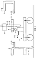
- a pin 1 shows a part of a ceiling mount 1 with a pin 2 fastened to it and extending vertically upwards.
- a pin 4 which serves as a patient transport device, has a pin 4, which also extends vertically upwards, on a frame part.
- a carriage 5 is provided which has a lifting device 6 on a chassis, which has a piston 7 which can be extended or retracted in height and which can be moved via a pneumatic device or via a corresponding drive to be actuated by a crank 8. At its upper free end, the piston 7 has a third pin 9, which also extends upwards in the vertical direction. The alignment of the three pins 2, 4 and 9 is parallel to each other.
- a carrier 11 carrying the medical devices 10 of the infusion supply device has a carrier rod 12 for mounting the devices 10 thereon and a plate-shaped element forming a coupling device 13.
- the coupling device 13 comprises an essentially plate-shaped base body 14.
- a vertical bore 15 extends through the center of the plate for receiving the support rod 12.
- a locking element 16 designed as an asymmetrically mounted pivot pin is provided for locking the coupling device 13 with the support rod 12. By turning this element, the locking between these two parts can be released and the height of the coupling device can be shifted on the support rod 12.
- the coupling device has, symmetrically to the bore 15 receiving the support rod 12, two recesses 17, 18 extending parallel to the axis of the bore. As can best be seen from FIG. 2, the two recesses each have conical walls that taper upwards. As can best be seen from FIGS. 2 to 4, a first slide 19 is provided near the upper edge of the recesses and a second slide 20 is provided near the lower edge of the recesses.
- the two sliders are in one Direction perpendicular to the axis direction of the recesses 17 and 18 and thus to the axis of the support rod 12 is displaceable.
- the first slide 19 has a first recess 24, the dimension of which is selected such that it corresponds to the size of the recess 17 when the first slide is in a corresponding pushed-back position. Furthermore, a second recess 25 is provided which, as can best be seen from FIG. 3, is designed as an elongated hole. The diameter is selected so that the support rod 12 is guided in the slot. Stops 26, 27, which are firmly connected to the base body 14, are arranged in the recesses 22, 23. Between these stops and the stop surfaces 21 of the recesses 22, 23 lying opposite them, compression springs 28, 29 are arranged under prestress. The dimensions of the first slider and the first recess 24 are dimensioned such that the slider in the position shown in FIGS.
- the slide can be moved against the spring force to such an extent that it completely opens the openings 17, 18.
- the first slide 19 is held and covered by a cover screwed to the base body 14.
- the second slide has a design corresponding to the first slide with a corresponding spring preload. It differs only with regard to the dimensions in that its free front edge 32 and its first recess 33 are dimensioned such that they protrude into the recesses 17, 18 in the free position caused by the spring preload in the manner shown in FIG. 2 and release the two recesses in their position pushed back against the spring preload.
- the second slide is also slidably covered by a cover 34 which is firmly screwed to the base body.
- the pin 9 connected to the piston 7 is at a small distance from its upper edge by one Undercut formed annular recess 35.
- the position of the annular recess is selected so that when it is inserted into the recess 18 of the coupling device 13 it lies exactly in the plane of the first slide 19.
- the dimensions of the recess are chosen so that the first slide 19 fits straight into the recess.
- the remaining pins, that is, the pin 2 on the ceiling stand 1 and the pin 4 on the bed 3 are designed so that they have a corresponding annular recess 36 at a small distance from their lower edge. This is chosen with respect to its position in the axial direction so that it lies in one plane with the second slide 20.
- the dimensions with regard to the depth and height of the annular recess are in turn chosen so that the second slide fits straight into the recess 36.
- the cone angle of the pins and the associated recesses is chosen to be approximately 22 °. This ensures that on the one hand pivoting of the coupling device 13 around the respective pin is possible, but that a certain braking effect against unintentional pivoting is nevertheless achieved by the angle of inclination and the force of gravity exerted.
- cylindrical pins with corresponding cylindrical recesses can also be selected.
- the support rod 12 with the coupling device 13 is mounted on the pin 2 of the ceiling mount 1 in the manner shown in FIG. 5.
- the guide takes place via the pin.
- a locking is achieved in that the second slide is due to the spring preload in the position shown in Fig. 2 and thereby engages in the annular recess 36.
- the pin 9 is moved upward in the direction of arrow 37 via the piston-cylinder device so that the pin 9 is inserted into the recess 18.
- the pin 9 pushes with its outer surface the front edge 32 protruding into the recess 18 against the spring force out of the recess. It is thereby achieved that the first recess 33 is also moved so that it is congruent with the recess 17, so that the pin 2 is unlocked at the same time.
- the piston 7 is extended so far up that the coupling device 13 with the support rod 12 and the devices 10 attached to it is lifted off the pin 2.
- this is pushed by the spring preload with its front edge 30 into the annular recess 35 and thus locks the Coupling device 13 with the pin 9.
- the transfer of the coupling device 13 with the support rod 12 to the pin 4 of the bed or the patient transport device takes place in the reverse manner by bringing the pin 4 into alignment, lowering it and finally lowering the pin 9 and finally locking it between Coupling device 13 and pin 4.
- journal of the mount has an annular recess on its upper edge, while the other journals have an annular recess on their lower edge, this arrangement can also be selected in reverse. It is only important that the spigot of the carriage on the one hand and the other spigots on the other hand differ in this regard.
- the device for moving which is designed as a carriage for driving, is replaced by a handle-like device 7 '.
- this is designed as a rod-like handle.
- the upper free end corresponds to the formation of the upper free end of the piston 7 of the mount. All other features are consistent with the embodiment shown in FIG. 1. 8, representations a), b) and c) correspond to the operating states shown in FIGS. 5 to 7.
Description
- Die Erfindung betrifft eine transportable medizinische Einrichtung, insbesondere Infusionsversorgungseinrichtung, mit einem Träger und daran befestigbaren Geräten für die Patientenversorgung.
- Aus der US-A-4,795,122 ist eine transportable medizinische Einrichtung, insbesondere Infusionsversorgungseinrichtung mit einem Träger und daran befestigbaren Geräten für die Patientenversorgung bekannt. Der Träger weist mit z.B. einem Patientenbett vorgesehenen Kupplungselementen verbindbare erste Kupplungselemente auf. Ferner weist der Träger in einer eine Verriegelungseinrichtung aufweisenden Kupplungseinrichtung, die beispielsweise an einem Deckenstativ vorgesehen ist, ein zweites Kupplungselement auf.
- Bekannt ist aus DE-A-31 45 310 ferner ein Geräteaufnahmesystem der Medizintechnik, bei dem das Gerät an einem Geräterahmen mit Führungsleisten befestigt ist. Mittels dieser Führungsleisten und zweier Sperren, die mit einem Riegel zusammenwirken, ist der Geräterahmen beim Transport mit einem Hubwagen und am Einsatzort mit einer Rahmenaufnahme verbindbar.
- Dieses System ist relativ platzaufwendig und für schwere und voluminöse Geräte vorgesehen.
- Aus der DE-B-28 12 074 ist weiter eine Patientenlagerungsplatte bekannt, die von einem Fahrgestell auf ein Tischgestell umsetzbar ist und bei der zur Verbindung mit dem Fahr- beziehungsweise Tischgestell Kupplungen mit schwenkbaren Klinken vorgesehen sind. Diese Verriegelung ermöglicht eine Schwenkung der Patientenlagerungsplatte um 360° um eine horizontale Achse und sichert deren zuverlässige Halterung unabhängig von etwaigen Bedienungsfehlern.
- Diese Vorrichtung ist - ihrem Einsatzzweck entsprechend - groß und aufwendig; letzteres gilt auch für die Kupplungen und Verriegelungen.
- Aufgabe der Erfindung ist es, die Konstruktion so auszubilden, daß die Abkupplung und Übergabe von der stationären Einrichtung zu der Patiententransporteinrichtung und umgekehrt auf besonders einfache und sichere Weise verläuft.
- Diese Aufgabe wird durch die im Patentanspruch 1 gekennzeichnete transportable medizinische Einrichtung gelöst.
- Weiterbildungen der Erfindung sind in den Unteransprüchen gekennzeichnet.
- Es folgt die Beschreibung von Ausführungsbeispielen anhand der Figuren. Von den Figuren zeigen:
- Fig. 1
- eine schematische Darstellung einer transportablen medizinischen Einrichtung mit Stativ und Patiententransporteinrichtung;
- Fig. 2
- einen Schnitt durch die mit den Kopplungselementen zusammenwirkende Kopplungseinrichtung in entkoppeltem Zustand;
- Fig. 3
- eine Ansicht der in Fig. 2 gezeigten Vorrichtung von oben mit abgenommener Abdeckung;
- Fig. 4
- eine Draufsicht auf die in Fig. 2 gezeigte Vorrichtung von unten mit abgenommener Abdeckung;
- Fig. 5
- die in Fig. 2 gezeigte Vorrichtung mit verriegeltem Zapfen einer Patiententransporteinrichtung oder der stationären Einrichtung;
- Fig. 6
- die in Fig. 5 gezeigte Darstellung mit beiden in die Kopplungseinrichtung eingeführten Zapfen;
- Fig. 7
- die in Fig. 5 dargestellte Vorrichtung, bei der nur der Zapfen der Lafette eingesetzt und verriegelt ist; und
- Fig. 8
- eine der in Fig. 1 entsprechende Darstellung einer abgewandelten Ausführungsform.
- Fig. 1 zeigt einen Teil eines Deckenstativs 1 mit einem sich an diesem befestigten und in vertikaler Richtung nach oben erstreckenden Zapfen 2. An einem Bett 3, welches als Patiententransporteinrichtung dient, ist an einem Rahmenteil ein sich ebenfalls vertikal nach oben erstreckender Zapfen 4 vorgesehen. Es ist eine Lafette 5 vorgesehen, die auf einem Fahrgestell eine Hubeinrichtung 6 aufweist, die einen in der Höhe ausfahrbaren bzw. einfahrbaren Kolben 7 aufweist, der über eine Pneumatikeinrichtung oder über einen entsprechenden mit einer Kurbel 8 zu betätigenden Antrieb bewegbar ist. An seinem oberen freien Ende weist der Kolben 7 einen dritten Zapfen 9 auf, der sich ebenfalls in vertikaler Richtung nach oben erstreckt. Die Ausrichtung der drei Zapfen 2, 4 und 9 ist parallel zueinander.
- Ein die medizinischen Geräte 10 der Infusionsversorgungseinrichtung tragender Träger 11 weist eine Trägerstange 12 zum Montieren der Geräte 10 an derselben und ein eine Kupplungseinrichtung 13 bildendes plattenförmiges Element auf. Die Kupplungseinrichtung 13 umfaßt einen im wesentlichen plattenförmigen Grundkörper 14. Durch den Mittelpunkt der Platte erstreckt sich eine vertikale Bohrung 15 zur Aufnahme der Trägerstange 12. Zum Verriegeln der Kupplungseinrichtung 13 mit der Trägerstange 12 ist ein als asymmetrisch gelagerter Drehbolzen ausgebildetes Verriegelungselement 16 vorgesehen. Durch Verdrehen dieses Elementes kann die Verriegelung zwischen diesen beiden Teilen gelöst und die Kupplungseinrichtung höhenmäßig auf der Trägerstange 12 verschoben werden.
- Die Kupplungseinrichtung weist symmetrisch zu der die Trägerstange 12 aufnehmenden Bohrung 15 zwei sich parallel zur Achse der Bohrung erstreckende Ausnehmungen 17, 18 auf. Die beiden Ausnehmungen haben, wie am besten aus Fig. 2 ersichtlich ist, jeweils sich nach oben verjüngende konische Wandungen. Wie am besten aus den Fig. 2 bis 4 ersichtlich ist, ist nahe des oberen Randes der Ausnehmungen ein erster Schieber 19 und nahe des unteren Randes der Ausnehmungen ein zweiter Schieber 20 vorgesehen. Die beiden Schieber sind in einer Richtung senkrecht zur Achsenrichtung der Ausnehmungen 17 und 18 und damit zur Achse der Trägerstange 12 verschiebbar. Der erste Schieber 19 weist eine erste Ausnehmung 24 auf, deren Abmessung so gewählt ist, daß sie der Größe der Ausnehmung 17 entspricht, wenn sich der erste Schieber in einer entsprechenden zurückgeschobenen Stellung befindet. Ferner ist eine zweite Ausnehmung 25 vorgesehen, die, wie am besten aus Fig. 3 ersichtlich ist, als Langloch ausgebildet ist. Der Durchmesser ist so gewählt, daß in dem Langloch die Trägerstange 12 geführt wird. In den Ausnehmungen 22, 23 sind mit dem Grundkörper 14 fest verbundene Anschläge 26, 27 angeordnet. Zwischen diesen Anschlägen und den diesen gegenüberliegenden Anschlagsflächen 21 der Ausnehmungen 22, 23 sind Druckfedern 28, 29 unter Vorspannung angeordnet. Die Abmessung des ersten Schiebers und der ersten Ausnehmung 24 sind so bemessen, daß der Schieber in der in den Fig. 2 und 3 gezeigten, durch die Federvorspannung bedingten Stellung mit seinem freien vorderen Rand 30 bzw. einem Rand 31 der Ausnehmung 24 jeweils in die Ausnehmungen 17, 18 hineinreicht. Andererseits kann der Schieber entgegen der Federkraft soweit verschoben werden, daß er die Öffnungen 17, 18 völlig freigibt. Der erste Schieber 19 ist durch einen mit dem Grundkörper 14 verschraubten Deckel gehalten und abgedeckt.
- Der zweite Schieber weist eine dem ersten Schieber entsprechende Ausbildung mit einer entsprechenden Federvorspannung auf. Er unterscheidet sich lediglich bezüglich der Abmessungen insoweit, als sein freier vorderer Rand 32 und seine erste Ausnehmung 33 so bemessen sind, daß sie in der durch die Federvorspannung bedingten freien Stellung in der in Fig. 2 gezeigten Weise in die Ausnehmungen 17, 18 hineinragen und in ihrer gegen die Federvorspannung zurückgeschobenen Stellung die beiden Ausnehmungen freigeben. Auch der zweite Schieber ist durch einen mit dem Grundkörper fest verschraubten Deckel 34 verschiebbar abgedeckt.
- Der mit dem Kolben 7 verbundene Zapfen 9 weist in einem kleinen Abstand von seinem oberen Rand eine durch eine Hinterschneidung gebildete ringförmige Ausnehmung 35 auf. Die Lage der ringförmigen Ausnehmung ist so gewählt, daß sie bei Einführung in die Ausnehmung 18 der Kopplungseinrichtung 13 genau in der Ebene des ersten Schiebers 19 liegt. Die Abmessungen der Ausnehmung sind so gewählt, daß der erste Schieber 19 gerade in die Ausnehmung hineinpaßt. Die übrigen Zapfen, also der Zapfen 2 am Deckenstativ 1 und der Zapfen 4 am Bett 3 sind so ausgebildet, daß sie in einem kleinen Abstand von ihrem unteren Rand eine entsprechende ringförmige Ausnehmung 36 aufweisen. Diese ist bezüglich ihrer Lage in axialer Richtung so gewählt, daß sie in einer Ebene mit dem zweiten Schieber 20 liegt. Die Abmessungen bezüglich Tiefe und Höhe der ringförmigen Ausnehmung sind wiederum so gewählt, daß der zweite Schieber gerade in die Ausnehmung 36 hineinpaßt.
- In dem gezeigten Ausführungsbeispiel ist der Kegelwinkel der Zapfen und der zugehörigen Ausnehmungen mit etwa 22° gewählt. Dadurch wird erreicht, daß einerseits ein Verschwenken der Kupplungseinrichtung 13 um den jeweiligen Zapfen möglich ist, daß aber durch den Neigungswinkel und die ausgeübte Schwerkraft doch eine gewisse Bremswirkung gegen unbeabsichtigtes Verschwenken erreicht wird. Anstelle der kegelförmigen Zapfen können auch zylindrische Zapfen mit entsprechend zylindrischen Ausnehmungen gewählt werden.
- Im weiteren wird die Funktionsweise der beschriebenen Vorrichtung am Beispiel des Abnehmens der die Trägerstange 12 tragenden Kupplungseinrichtung 13 von dem Zapfen 2 auf den Zapfen 9 der Lafette erläutert.
- Zunächst ist die Trägerstange 12 mit der Kupplungseinrichtung 13 in der in Fig. 5 gezeigten Weise auf dem Zapfen 2 des Deckenstativs 1 gelagert. Die Führung erfolgt über den Zapfen. Eine Verriegelung ist dadurch erreicht, daß der zweite Schieber bedingt durch die Federvorspannung sich in der in Fig. 2 gezeigten Stellung befindet und dadurch in die ringförmige Ausnehmung 36 eingreift.
- Zum Übernehmen der Trägerstange mit der zugehörigen Kupplungseinrichtung wird der Zapfen 9 über die Kolbenzylindereinrichtung so nach oben in Richtung des Pfeiles 37 gefahren, daß der Zapfen 9 in die Ausnehmung 18 eingeführt wird. Beim Einführen schiebt der Zapfen 9 mit seiner Mantelfläche den in die Ausnehmung 18 hineinragenden vorderen Rand 32 entgegen der Federkraft aus der Ausnehmung heraus. Dadurch wird erreicht, daß auch die erste Ausnehmung 33 so verschoben wird, daß sie mit der Ausnehmung 17 kongruent ist, so daß gleichzeitig der Zapfen 2 entriegelt wird.
- Im nächsten Schritt wird der Kolben 7 weiter so weit nach oben ausgefahren, daß die Kupplungseinrichtung 13 mit der Trägerstange 12 und den daran befestigten Geräten 10 von dem Zapfen 2 abgehoben wird. Sobald der Zapfen 2 aus der Ausnehmung 17 soweit zurückgezogen wird, daß der Mantel des Zapfens 2 nicht mehr gegen den Rand des federvorgespannten ersten Schiebers 19 drückt, wird dieser durch die Federvorspannung mit seinem vorderen Rand 30 in die ringförmige Ausnehmung 35 hineingeschoben und verriegelt damit die Kupplungseinrichtung 13 mit dem Zapfen 9. Das Übergeben der Kupplungseinrichtung 13 mit der Trägerstange 12 an den Zapfen 4 des Bettes bzw. der Patiententransporteinrichtung erfolgt in umgekehrter Weise durch Indeckungbringen mit dem Zapfen 4, Absenken auf diesen und abschließendes Absenken des Zapfens 9 und abschließende Verriegelung zwischen Kupplungseinrichtung 13 und Zapfen 4.
- Bei der oben beschriebenen Ausführungsform weist der Zapfen der Lafette an seinem oberen Rand eine ringförmige Ausnehmung auf, während die übrigen Zapfen an ihrem unteren Rand eine ringförmige Ausnehmung aufweisen, diese Anordnung kann auch umgekehrt gewählt werden. Entscheidend ist nur, daß der Zapfen der Lafette einerseits und die übrigen Zapfen andererseits sich diesbezüglich unterscheiden.
- Bei der in Fig. 8 gezeigten Ausführungsform ist die als Lafette zum Fahren ausgebildete Einrichtung zum Umsetzen ersetzt durch eine griffartige Einrichtung 7'. Diese ist in ihrem unteren Teil als stangenartiger Griff ausgebildet. Das obere freie Ende stimmt mit der Ausbildung des oberen freien Endes des Kolbens 7 der Lafette überein. Alle übrigen Merkmale sind mit der in Fig. 1 gezeigten Ausführungsform übereinstimmend.
In der Fig. 8 entsprechen die Darstellungen a), b) und c) den in den Fig. 5 bis 7 gezeigten Betriebszuständen.
Claims (9)
- Transportable medizinische Einrichtung, insbesondere Infusionsversorgungseinrichtung, mit einem Träger (12) und daran befestigbaren Geräten (10) für die Patientenversorgung, wobei der Träger (12) eine Kupplungseinrichtung (13) und die Kupplungseinrichtung (13) eine Verriegelungseinrichtung (19, 20) aufweist,
einer Einrichtung (5) zum Umsetzen des Trägers mit einem mit der Kupplungseinrichtung (13) zusammenwirkenden ersten Kupplungselement (9),
einem an einer stationären Einrichtung, insbesondere einem stationären Stativ (1), befestigbaren zweiten, mit der Kupplungseinrichtung (13) zusammenwirkenden Kupplungselement (2) und
einem an einer Patiententransporteinrichtung (3) befestigbaren dritten, mit der Kupplungseinrichtung (13) zusammenwirkenden Kupplungselement (4),
wobei die Kupplungseinrichtung (13) so ausgebildet ist, daß eines oder zwei der Kupplungselemente (2, 4, 9) mit ihr im Eingriff stehen können, und die Verriegelungseinrichtung so ausgebildet ist, daß bei Ineinandergreifen von einem Kupplungselement und der Kupplungseinrichtung diese mit dem Kupplungselement verriegelt ist und daß bei Ineinandergreifen von zwei Kupplungselementen mit der Kupplungseinrichtung zum Lösen der jeweiligen lösbaren Verbindung die Kupplungseinrichtung von den Kupplungselementen entriegelt ist. - Transportable medizinische Einrichtung nach Anspruch 1, dadurch gekennzeichnet, daß die Kupplungselemente als hervorstehende Zapfen (2, 4, 9) ausgebildet sind und die Kupplungseinrichtung (13) der Form der Zapfen angepaßte Ausnehmungen aufweist.
- Transportable medizinische Einrichtung nach Anspruch 2, dadurch gekennzeichnet, daß die Zapfen (2, 4, 9) und die Ausnehmungen (17, 18) jeweils vertikal ausgerichtet sind.
- Transportable medizinische Einrichtung nach Anspruch 3, dadurch gekennzeichnet, daß die Zapfen (2, 4, 9) nach oben hervorstehen.
- Transportable medizinische Einrichtung nach Anspruch 4, dadurch gekennzeichnet, daß die Zapfen (2, 4, 9) einen konisch verlaufenden Mantelabschnitt aufweisen.
- Transportable medizinische Einrichtung nach einem der Ansprüche 2 bis 5,
dadurch gekennzeichnet, daß die mit der stationären Einrichtung (1) und der Patiententransporteinrichtung (3) verbundenen Zapfen (2, 4) an einer ersten Stelle und der Zapfen (9) der Kupplungseinrichtung (13) an einer zweiten Stelle jeweils eine Ausnehmung (35, 36) zum Eingreifen der Verriegelungseinrichtung (19, 20) aufweisen. - Transportable medizinische Einrichtung nach Anspruch 6,
dadurch gekennzeichnet, daß die Verriegelungseinrichtung einen ersten Schieber (19) und einen zweiten Schieber (20) aufweist, die jeweils so federvorgespannt sind, daß die Schieber (19, 20) an dem der ersten beziehungsweise zweiten Stelle der Zapfen (2, 4) beziehungsweise des Zapfens (9) entsprechenden Ort in deren Ausnehmung (35, 36) hervorstehen und gegen die Federvorspannung aus der Ausnehmung herausschiebbar sind. - Transportable medizinische Einrichtung nach Anspruch 6 oder 7,
dadurch gekennzeichnet, daß die Ausnehmungen als Hinterschneidungen (35, 36) ausgebildet sind und die erste und die zweite Stelle in axialer Richtung der Zapfen gesehen einen Abstand voneinander aufweisen. - Transportable medizinische Einrichtung nach einem der Ansprüche 1 bis 8,
dadurch gekennzeichnet, daß die Einrichtung zum Umsetzen des Trägers als Lafette (5) zum Fahren des Trägers ausgebildet ist.
Applications Claiming Priority (3)
| Application Number | Priority Date | Filing Date | Title |
|---|---|---|---|
| DE4113228 | 1991-04-23 | ||
| DE4113228 | 1991-04-23 | ||
| PCT/EP1992/000889 WO1992018085A1 (de) | 1991-04-23 | 1992-04-22 | Transportable medizinische einrichtung insbesondere infusionsversorgungseinrichtung |
Publications (2)
| Publication Number | Publication Date |
|---|---|
| EP0536368A1 EP0536368A1 (de) | 1993-04-14 |
| EP0536368B1 true EP0536368B1 (de) | 1995-09-27 |
Family
ID=6430178
Family Applications (1)
| Application Number | Title | Priority Date | Filing Date |
|---|---|---|---|
| EP92909105A Expired - Lifetime EP0536368B1 (de) | 1991-04-23 | 1992-04-22 | Transportable medizinische einrichtung insbesondere infusionsversorgungseinrichtung |
Country Status (10)
| Country | Link |
|---|---|
| US (1) | US5306109A (de) |
| EP (1) | EP0536368B1 (de) |
| JP (1) | JPH05507873A (de) |
| AT (1) | ATE128347T1 (de) |
| CA (1) | CA2085011A1 (de) |
| DE (1) | DE59203824D1 (de) |
| FI (1) | FI925721A0 (de) |
| NO (1) | NO924973L (de) |
| WO (1) | WO1992018085A1 (de) |
| ZA (1) | ZA922901B (de) |
Cited By (1)
| Publication number | Priority date | Publication date | Assignee | Title |
|---|---|---|---|---|
| DE102013006700A1 (de) * | 2013-04-18 | 2014-10-23 | Dräger Medical GmbH | Medizinisches Gerätesystem, medizinisches Gerät und bodengebundenes Gestell für ein medizinisches Gerät |
Families Citing this family (52)
| Publication number | Priority date | Publication date | Assignee | Title |
|---|---|---|---|---|
| JP2001508237A (ja) * | 1997-01-13 | 2001-06-19 | シーメンス アクチエンゲゼルシヤフト | 電気部品を自動取付装置に供給するための装置 |
| US6725483B2 (en) * | 1997-01-31 | 2004-04-27 | Hill-Rom Services, Inc. | Apparatus and method for upgrading a hospital room |
| US6095468A (en) * | 1998-03-27 | 2000-08-01 | Hill-Rom, Inc. | Support arm for a service column |
| USD418603S (en) * | 1998-06-26 | 2000-01-04 | Hill-Rom, Inc. | Power column |
| WO2000009061A1 (en) * | 1998-08-14 | 2000-02-24 | The General Hospital Corporation Doing Business As Massachussets General Hospital | Transfer system for portable patient care apparatus |
| DE19928835C1 (de) | 1999-06-24 | 2001-01-11 | Draeger Medizintech Gmbh | Bewegliche medizinische Versorgungsvorrichtung |
| AUPQ958200A0 (en) * | 2000-08-22 | 2000-09-14 | Eggleston, Gray John | Coupling assembly |
| AU2002309987A1 (en) * | 2001-05-25 | 2002-12-09 | Hill-Rom Services, Inc. | Modular patient room |
| US7083150B2 (en) * | 2003-03-18 | 2006-08-01 | Hill-Rom Services, Inc. | Patient line management system |
| US7065811B2 (en) * | 2003-03-18 | 2006-06-27 | Hill-Rom Services, Inc. | Radial arm system for patient care equipment |
| US7065812B2 (en) * | 2003-03-18 | 2006-06-27 | Hill-Rom Services, Inc. | Patient care equipment management system |
| WO2005037164A2 (en) * | 2003-10-13 | 2005-04-28 | Hill-Rom Services, Inc. | Patient care equipment support system |
| US7849978B2 (en) | 2003-10-13 | 2010-12-14 | Hill-Rom Services, Inc. | Brake system for patient care equipment support arm |
| US7849537B2 (en) * | 2003-10-13 | 2010-12-14 | Hill-Rom Services, Inc. | Equipment support having rotatable bumpers and hooks |
| WO2005037163A2 (en) * | 2003-10-13 | 2005-04-28 | Hill-Rom Services, Inc. | Transferable patient care equipment support |
| US7418749B2 (en) * | 2003-10-13 | 2008-09-02 | Hill-Rom Services, Inc. | Patient care equipment support lock |
| US8100371B2 (en) * | 2003-12-15 | 2012-01-24 | Ergotech Health Systems Pty Ltd. | I.V. support stand and clamp apparatus |
| US7624463B2 (en) * | 2004-08-03 | 2009-12-01 | Hill-Rom Services, Inc. | Equipment support rail for hospital bed |
| US8051610B2 (en) * | 2004-09-22 | 2011-11-08 | Hill-Rom Services, Inc. | Patient flatwall system |
| US8191909B2 (en) * | 2005-01-10 | 2012-06-05 | Livengood Engineering, Inc. | Modular patient support system |
| WO2006074473A2 (en) * | 2005-01-10 | 2006-07-13 | Livengood Engineering, Inc. | Modular patient support system |
| US7884735B2 (en) * | 2005-02-11 | 2011-02-08 | Hill-Rom Services, Inc. | Transferable patient care equipment support |
| US7770247B2 (en) * | 2005-05-02 | 2010-08-10 | Hill-Rom Services, Inc. | Brake system for wall arm |
| TW200701968A (en) * | 2005-05-06 | 2007-01-16 | Steris Inc | Transfer system and transfer device |
| WO2008042346A2 (en) * | 2006-09-28 | 2008-04-10 | Stryker Corporation | Medical equipment transfer arrangement |
| US7845601B1 (en) | 2006-11-09 | 2010-12-07 | Modular Services Company | Medical equipment transport system |
| MX2009006686A (es) * | 2006-12-21 | 2009-10-07 | Ind Steeltek Internat Inc | Sistema de soporte medico. |
| US7661641B2 (en) * | 2006-12-22 | 2010-02-16 | Linvatec Corporation | Medical equipment transfer system |
| US8104729B2 (en) * | 2007-03-09 | 2012-01-31 | Hill-Rom Services, Inc. | Transferable patient care equipment support |
| NL2000571C2 (nl) * | 2007-04-03 | 2008-10-06 | Ihb B V | Tussen houders verplaatsbare draaginrichting voor benodigdheden voor het verzorgen van een patient, en werkwijze voor het verplaatsen van een dergelijke inrichting. |
| US7865983B2 (en) * | 2007-04-26 | 2011-01-11 | Hill-Rom Services, Inc. | Patient care equipment support transfer system |
| US7798456B2 (en) * | 2007-08-21 | 2010-09-21 | Hill-Rom Services, Inc. | Transferable patient care equipment support |
| US7748672B2 (en) | 2007-09-07 | 2010-07-06 | Hill-Rom Services, Inc. | Transferable patient care equipment support |
| US20110064548A1 (en) * | 2009-09-17 | 2011-03-17 | Acist Medical Systems, Inc. | Apparatus and methods for medical device transfer |
| US8579244B2 (en) | 2010-05-10 | 2013-11-12 | Lifespan Healthcare, Llc | Secure equipment transfer system |
| US9404616B2 (en) | 2010-05-10 | 2016-08-02 | Nexxspan Healthcare, Llc | Secure equipment transfer system |
| US9528536B2 (en) | 2010-05-10 | 2016-12-27 | Nexxspan Healthcare, Llc | Secure equipment transfer system |
| CN102992012B (zh) * | 2011-09-15 | 2015-07-15 | 鸿富锦精密工业(深圳)有限公司 | 定位机构 |
| EP2800545B1 (de) * | 2012-01-04 | 2016-07-27 | Fresenius Vial SAS | Haltegestell für medizinische vorrichtungen |
| AU2013404103B2 (en) * | 2013-10-28 | 2017-10-19 | Nexxspan Healthcare, Llc | Secure equipment transfer system |
| USD783389S1 (en) | 2015-03-12 | 2017-04-11 | Lgms, Llc | Mounting plate for a patient support cart |
| USD787073S1 (en) | 2015-03-12 | 2017-05-16 | Lgms, Llc | Patient support cart with mounting plate |
| CA2982549C (en) * | 2015-04-14 | 2023-03-14 | Nexxspan Healthcare, Llc | Secure equipment transfer system |
| US9585806B2 (en) | 2015-06-11 | 2017-03-07 | Acist Medical Systems, Inc. | Variable rate bedrail clamp |
| US10258424B2 (en) | 2016-02-22 | 2019-04-16 | Nexxspan Healthcare, Llc | Sacrificial mechanical link |
| US10258524B2 (en) | 2016-02-22 | 2019-04-16 | Nexxspan Healthcare, Llc | Transfer system with sacrificial mechanical link |
| US9889787B2 (en) * | 2016-04-19 | 2018-02-13 | Marc S. Thomas | Mobile auxiliary transfer lift caddy |
| JP7135411B2 (ja) * | 2018-05-02 | 2022-09-13 | 村田機械株式会社 | 搬送システム |
| US10589770B1 (en) * | 2018-09-06 | 2020-03-17 | Christie Lites Enterprises Canada Inc. | Fixture securing system and method of use |
| WO2021071944A1 (en) | 2019-10-08 | 2021-04-15 | Nexxspan Healthcare, Llc | Transfer device docking indicator |
| CN110841124A (zh) * | 2019-12-02 | 2020-02-28 | 刘昆 | 一种血液透析监测护理装置 |
| US20230181395A1 (en) * | 2021-12-09 | 2023-06-15 | DePuy Synthes Products, Inc. | Mechanism for the transfer of medical device to bed rail |
Family Cites Families (18)
| Publication number | Priority date | Publication date | Assignee | Title |
|---|---|---|---|---|
| US3183777A (en) * | 1962-10-26 | 1965-05-18 | Carl A Damm | Connector aligning device |
| DE1196815B (de) * | 1964-03-21 | 1965-07-15 | Stierlen Werke Ag | Operationstisch mit ortsfestem Unterteil und transportabler Liegeflaeche |
| US3512387A (en) * | 1967-06-21 | 1970-05-19 | Tridan Tool & Machine | Ring lock for tube expander |
| SE329467B (de) * | 1969-03-13 | 1970-10-12 | Hydraul Verken Ab | |
| CA992522A (en) * | 1972-08-29 | 1976-07-06 | Ake Jacobsson | Bed-plant for hospitals |
| DE2812074C2 (de) * | 1978-03-20 | 1980-01-10 | Siemens Ag, 1000 Berlin Und 8000 Muenchen | Untersuchungseinrichtung |
| JPS57194861A (en) * | 1981-05-25 | 1982-11-30 | Murata Mach Ltd | Automatic transfer system of workpiece in machine shop |
| DE3145310C2 (de) * | 1981-11-14 | 1984-11-08 | Drägerwerk AG, 2400 Lübeck | Befestigungssystem für medizintechnische Geräte |
| US4724844A (en) * | 1985-06-26 | 1988-02-16 | Stephen Rafelson | Vital sign modular unit |
| US4795122A (en) * | 1986-07-15 | 1989-01-03 | Cleveland Clinic Foundation | Patient equipment transport and support system |
| GB8812634D0 (en) * | 1988-05-27 | 1988-06-29 | Caterpillar Ind Inc | Load positioning assembly & method |
| US4945592A (en) * | 1988-09-30 | 1990-08-07 | The General Hospital Corporation | Transport system for portable patient care apparatus |
| DE3902027C1 (de) * | 1989-01-25 | 1990-03-29 | Hans 7052 Schwaikheim De Jung | |
| DE3917892C1 (de) * | 1989-06-01 | 1990-12-06 | F.M.K. Kreuzer Gmbh & Co Kg, 8039 Puchheim, De | |
| DE3924390C1 (de) * | 1989-07-24 | 1990-08-23 | Stierlen-Maquet Ag, 7550 Rastatt, De | |
| US5117521A (en) * | 1990-05-16 | 1992-06-02 | Hill-Rom Company, Inc. | Care cart and transport system |
| US5135191A (en) * | 1991-05-09 | 1992-08-04 | Jagco Corporation | Medical support system |
| US5149036A (en) * | 1991-08-29 | 1992-09-22 | Sheehan Gerald F | Device for attaching an IV pole to a hospital bed or the like |
-
1992
- 1992-04-22 CA CA002085011A patent/CA2085011A1/en not_active Abandoned
- 1992-04-22 JP JP92508490A patent/JPH05507873A/ja active Pending
- 1992-04-22 US US07/938,158 patent/US5306109A/en not_active Expired - Fee Related
- 1992-04-22 EP EP92909105A patent/EP0536368B1/de not_active Expired - Lifetime
- 1992-04-22 AT AT92909105T patent/ATE128347T1/de not_active IP Right Cessation
- 1992-04-22 ZA ZA922901A patent/ZA922901B/xx unknown
- 1992-04-22 DE DE59203824T patent/DE59203824D1/de not_active Expired - Fee Related
- 1992-04-22 WO PCT/EP1992/000889 patent/WO1992018085A1/de active IP Right Grant
- 1992-12-16 FI FI925721A patent/FI925721A0/fi not_active Application Discontinuation
- 1992-12-22 NO NO92924973A patent/NO924973L/no unknown
Cited By (2)
| Publication number | Priority date | Publication date | Assignee | Title |
|---|---|---|---|---|
| DE102013006700A1 (de) * | 2013-04-18 | 2014-10-23 | Dräger Medical GmbH | Medizinisches Gerätesystem, medizinisches Gerät und bodengebundenes Gestell für ein medizinisches Gerät |
| DE102013006700B4 (de) * | 2013-04-18 | 2017-02-09 | Drägerwerk AG & Co. KGaA | Medizinisches Gerätesystem, medizinisches Gerät, bodengebundenes Gestell für ein medizinisches Gerät und Verfahren für die Umwandlung eines deckengebundenen medizinischen Geräts in ein medizinisches Gerätesystem |
Also Published As
| Publication number | Publication date |
|---|---|
| FI925721A (fi) | 1992-12-16 |
| JPH05507873A (ja) | 1993-11-11 |
| CA2085011A1 (en) | 1992-10-24 |
| WO1992018085A1 (de) | 1992-10-29 |
| US5306109A (en) | 1994-04-26 |
| NO924973D0 (no) | 1992-12-22 |
| NO924973L (no) | 1992-12-22 |
| EP0536368A1 (de) | 1993-04-14 |
| ATE128347T1 (de) | 1995-10-15 |
| DE59203824D1 (de) | 1995-11-02 |
| FI925721A0 (fi) | 1992-12-16 |
| ZA922901B (en) | 1992-12-30 |
Similar Documents
| Publication | Publication Date | Title |
|---|---|---|
| EP0536368B1 (de) | Transportable medizinische einrichtung insbesondere infusionsversorgungseinrichtung | |
| WO1994004113A1 (de) | Transportable medizinische einrichtung, insbesondere infusionsversorgungseinrichtung | |
| EP1607364B1 (de) | Kranballastierungssystem | |
| EP0457246A1 (de) | Mobiles Patientenlagersystem | |
| DE3604397A1 (de) | Laengeneinstellbare tragsaeule | |
| DE60221952T2 (de) | Tischstuhl mit einfacher und sicherer Positionierung | |
| DE102011001924B4 (de) | Transfereinrichtung für eine Presse oder Pressenstraße mit Achsantrieb und auswechselbarem Grundträger | |
| DE3804199A1 (de) | Kamerahalter | |
| DE202018101158U1 (de) | Verstellvorrichtung für eine Kopfstütze | |
| DE3239948C1 (de) | Vorrichtung zum Betaetigen eines Schieberverschlusses | |
| EP0071728B1 (de) | Ballastgewichtanordnung an landwirtschaftlichen Zugmaschinen | |
| EP0913139A1 (de) | Modulares OP-Tischsystem | |
| EP3083097B1 (de) | Kupplungssystem | |
| DE102018122634A1 (de) | Ladungs-Sicherungs-System sowie Fahrzeug umfassend ein solches System und ein Verfahren zur Ladungs-Sicherung | |
| DE3743832C2 (de) | ||
| EP0578072B1 (de) | Vorrichtung zum Halten einer Anhänge-Kupplungs-Tragplatte | |
| DE3311609C2 (de) | Schnellverschluß für die lösbare Verbindung zweier Bauteile | |
| EP0081740A2 (de) | Gerät zur Viehgeburtshilfe | |
| EP1528164A1 (de) | Vorrichtung zur lösbaren Kupplung eines Arbeitsgerätes, insbesondere einer Ladeschwinge, mit einem Tragfahrzeug | |
| EP0019243A1 (de) | Stativ für Projektionsleinwände | |
| DE766129C (de) | Kupplungseinrichtung, insbesondere zum Anhaengen von landwirtschaftlichen Maschinen an eine Zugmaschine | |
| DE1940452C3 (de) | Vorrichtung zum Kuppeln von Containern | |
| EP0401404A1 (de) | Höhenverstellbare Anhängerkupplung | |
| DE975231C (de) | Gelenkige Kappenverbindung | |
| EP1471183A1 (de) | Vorrichtung zur Befestigung einer Bake an einer Fussplatte |
Legal Events
| Date | Code | Title | Description |
|---|---|---|---|
| PUAI | Public reference made under article 153(3) epc to a published international application that has entered the european phase |
Free format text: ORIGINAL CODE: 0009012 |
|
| 17P | Request for examination filed |
Effective date: 19921109 |
|
| AK | Designated contracting states |
Kind code of ref document: A1 Designated state(s): AT BE CH DE DK ES FR GB IT LI NL SE |
|
| 17Q | First examination report despatched |
Effective date: 19940804 |
|
| GRAA | (expected) grant |
Free format text: ORIGINAL CODE: 0009210 |
|
| AK | Designated contracting states |
Kind code of ref document: B1 Designated state(s): AT BE CH DE DK ES FR GB IT LI NL SE |
|
| PG25 | Lapsed in a contracting state [announced via postgrant information from national office to epo] |
Ref country code: NL Free format text: LAPSE BECAUSE OF FAILURE TO SUBMIT A TRANSLATION OF THE DESCRIPTION OR TO PAY THE FEE WITHIN THE PRESCRIBED TIME-LIMIT Effective date: 19950927 Ref country code: IT Free format text: LAPSE BECAUSE OF FAILURE TO SUBMIT A TRANSLATION OF THE DESCRIPTION OR TO PAY THE FEE WITHIN THE PRESCRIBED TIME-LIMIT;WARNING: LAPSES OF ITALIAN PATENTS WITH EFFECTIVE DATE BEFORE 2007 MAY HAVE OCCURRED AT ANY TIME BEFORE 2007. THE CORRECT EFFECTIVE DATE MAY BE DIFFERENT FROM THE ONE RECORDED. Effective date: 19950927 Ref country code: ES Free format text: THE PATENT HAS BEEN ANNULLED BY A DECISION OF A NATIONAL AUTHORITY Effective date: 19950927 Ref country code: DK Effective date: 19950927 |
|
| REF | Corresponds to: |
Ref document number: 128347 Country of ref document: AT Date of ref document: 19951015 Kind code of ref document: T |
|
| ET | Fr: translation filed | ||
| REF | Corresponds to: |
Ref document number: 59203824 Country of ref document: DE Date of ref document: 19951102 |
|
| GBT | Gb: translation of ep patent filed (gb section 77(6)(a)/1977) |
Effective date: 19951110 |
|
| PG25 | Lapsed in a contracting state [announced via postgrant information from national office to epo] |
Ref country code: SE Effective date: 19951227 |
|
| NLV1 | Nl: lapsed or annulled due to failure to fulfill the requirements of art. 29p and 29m of the patents act | ||
| PLBE | No opposition filed within time limit |
Free format text: ORIGINAL CODE: 0009261 |
|
| STAA | Information on the status of an ep patent application or granted ep patent |
Free format text: STATUS: NO OPPOSITION FILED WITHIN TIME LIMIT |
|
| 26N | No opposition filed | ||
| PGFP | Annual fee paid to national office [announced via postgrant information from national office to epo] |
Ref country code: GB Payment date: 19990324 Year of fee payment: 8 |
|
| PGFP | Annual fee paid to national office [announced via postgrant information from national office to epo] |
Ref country code: FR Payment date: 19990420 Year of fee payment: 8 |
|
| PGFP | Annual fee paid to national office [announced via postgrant information from national office to epo] |
Ref country code: CH Payment date: 19990422 Year of fee payment: 8 Ref country code: BE Payment date: 19990422 Year of fee payment: 8 Ref country code: AT Payment date: 19990422 Year of fee payment: 8 |
|
| PG25 | Lapsed in a contracting state [announced via postgrant information from national office to epo] |
Ref country code: GB Free format text: LAPSE BECAUSE OF NON-PAYMENT OF DUE FEES Effective date: 20000422 Ref country code: AT Free format text: LAPSE BECAUSE OF NON-PAYMENT OF DUE FEES Effective date: 20000422 |
|
| PG25 | Lapsed in a contracting state [announced via postgrant information from national office to epo] |
Ref country code: LI Free format text: LAPSE BECAUSE OF NON-PAYMENT OF DUE FEES Effective date: 20000430 Ref country code: CH Free format text: LAPSE BECAUSE OF NON-PAYMENT OF DUE FEES Effective date: 20000430 Ref country code: BE Free format text: LAPSE BECAUSE OF NON-PAYMENT OF DUE FEES Effective date: 20000430 |
|
| BERE | Be: lapsed |
Owner name: KREUZER G.M.B.H. + CO. OHG Effective date: 20000430 |
|
| GBPC | Gb: european patent ceased through non-payment of renewal fee |
Effective date: 20000422 |
|
| REG | Reference to a national code |
Ref country code: CH Ref legal event code: PL |
|
| PG25 | Lapsed in a contracting state [announced via postgrant information from national office to epo] |
Ref country code: FR Free format text: LAPSE BECAUSE OF NON-PAYMENT OF DUE FEES Effective date: 20001229 |
|
| REG | Reference to a national code |
Ref country code: FR Ref legal event code: ST |
|
| PGFP | Annual fee paid to national office [announced via postgrant information from national office to epo] |
Ref country code: DE Payment date: 20080415 Year of fee payment: 17 |
|
| PG25 | Lapsed in a contracting state [announced via postgrant information from national office to epo] |
Ref country code: DE Free format text: LAPSE BECAUSE OF NON-PAYMENT OF DUE FEES Effective date: 20091103 |