EP0534190B1 - Schleifmaschine für die Enden keramischer Henkel - Google Patents
Schleifmaschine für die Enden keramischer Henkel Download PDFInfo
- Publication number
- EP0534190B1 EP0534190B1 EP92115080A EP92115080A EP0534190B1 EP 0534190 B1 EP0534190 B1 EP 0534190B1 EP 92115080 A EP92115080 A EP 92115080A EP 92115080 A EP92115080 A EP 92115080A EP 0534190 B1 EP0534190 B1 EP 0534190B1
- Authority
- EP
- European Patent Office
- Prior art keywords
- grinding
- handle
- grinding machine
- machine according
- clamping means
- Prior art date
- Legal status (The legal status is an assumption and is not a legal conclusion. Google has not performed a legal analysis and makes no representation as to the accuracy of the status listed.)
- Expired - Lifetime
Links
Images

Classifications
-
- B—PERFORMING OPERATIONS; TRANSPORTING
- B28—WORKING CEMENT, CLAY, OR STONE
- B28B—SHAPING CLAY OR OTHER CERAMIC COMPOSITIONS; SHAPING SLAG; SHAPING MIXTURES CONTAINING CEMENTITIOUS MATERIAL, e.g. PLASTER
- B28B11/00—Apparatus or processes for treating or working the shaped or preshaped articles
- B28B11/18—Apparatus or processes for treating or working the shaped or preshaped articles for removing burr
-
- B—PERFORMING OPERATIONS; TRANSPORTING
- B24—GRINDING; POLISHING
- B24B—MACHINES, DEVICES, OR PROCESSES FOR GRINDING OR POLISHING; DRESSING OR CONDITIONING OF ABRADING SURFACES; FEEDING OF GRINDING, POLISHING, OR LAPPING AGENTS
- B24B19/00—Single-purpose machines or devices for particular grinding operations not covered by any other main group
- B24B19/008—Single-purpose machines or devices for particular grinding operations not covered by any other main group for grinding ceramics, pottery, table ware
Definitions
- the invention relates to a grinding machine for preparing the ends of a ceramic handle for garnishing to a vessel body, with a clamping device for the handle.
- handles are poured in pairs, then dried in white and deburred.
- the pairs of handles are then annealed and cut in the annealed state in a cutting device consisting of four adjustable cutting wheels.
- attachment surfaces at the ends of the handles are adapted to the outer profile of cups to which the handles are to be attached by a rotating grinding body. It is necessary that the grinding body has a profile complementary to the outer profile of the cups. Such a grinding wheel is expensive to manufacture and must often be dressed in order to maintain the specified profile. If the shape of the cups to which the handles are to be hinged changes, a correspondingly modified grinding wheel must be inserted into the known grinding machine.
- the invention has for its object to develop a grinding machine of the type mentioned in such a way that it can be converted with less effort for processing handles adapted to different profiles of vessel bodies.
- the grinding machine has two separate, against the clamping device adjustable grinding units with which the two ends of the handle can be ground at the same time, and that the grinding units are supported by pedestals, each with its own to the handle ends normal center plane of the handle are at least approximately normal pivot axis adjustable.
- the grinding bodies of the machine can either act directly on the ends of the handles or can be wrapped around by a grinding belt of known type.
- the grinding wheels have the shape of spherical rollers.
- bearing blocks of both grinding units are fastened to a common slide which can be advanced in the direction of the clamping device.
- the grinding machine according to the invention can also be further developed in that a supporting body which can be pivoted about the axis of the associated grinding body is fastened to each bearing block, and the grinding bodies are each driven by a separate motor via a belt drive, which is attached to the associated supporting body via a tensioning device is supported.
- This ensures that the motors can be arranged in an area in which they do not interfere, and the support body can be adjusted so that they do not collide with each other even when the grinding body must be brought into a position with respect to each other Grinding of handles for vessel bodies with a concave outer contour enables.
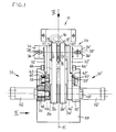
- the grinding machine shown has a clamping device 10 with two clamping jaws 12 and 14 arranged one above the other, between which a handle 16 can be clamped, the handle ends 18 and 18 'of which are to be ground.
- the handle 16 is symmetrical with respect to a central plane A, which corresponds to the mold division plane of a casting mold, in which the handle 16, possibly with other identical handles, has been cast.
- the central plane A is horizontal.
- the clamping device 10 can be arranged together with several identical clamping devices on a conveyor, for example on a turntable.
- the grinding machine also has a stationary housing 20 in the example shown, from which two horizontal piston rods 22 protrude in the direction of the clamping device 10.
- the piston rods 22 each belong to a pneumatic piston-cylinder unit of the usual type arranged within the housing 20 and together carry a slide 24 which can be moved back and forth in the direction of the double arrow B shown in FIGS. 1, 2 and 4.
- the carriage 24 carries two grinding units 30 and 30 'of the same type, which are arranged mirror-symmetrically to one another and, apart from the fact that they jointly participate in all the movements of the carriage 24, are independent of one another.
- Each of the grinding units 30 and 30 ' has a bearing block 32 or 32' with a foot 34 or 34 ', which has a transverse slot 36 or 36'.
- a longitudinal slot is formed in the slide 24 under the transverse slots 36 and 36 '.
- a clamping screw 38 or 38 ' extends through each of the transverse slots 36 and 36' and the associated longitudinal slot. It is thus possible to clamp the bearing blocks 32 and 32 'on the slide 24 at different distances from one another and in different ways, each pivoted about a vertical pivot axis C or C'.
- a grinding body 40 or 40' is mounted on an axle bolt 42 or 42 ', which defines an axis of rotation D or D' lying in the central plane A.
- the grinding wheels 40 and 40 ' are smooth, slightly spherical rollers made of steel, which are each mounted on a roller bearing 44.
- On each of the axle bolts 42 and 42 ' there is also a support body 46 or 46 'pivotally mounted about the associated axis of rotation D or D'.
- Each of the support bodies 46 and 46 ' has the shape of a vertical plate with a further bearing bolt 48 or 48' arranged parallel to the associated axle bolt 42 or 42 ', on which a rocker 50 or 50' is pivotably mounted in a vertical plane is.
- Each of the rockers 50 and 50 ' carries a motor 52 or 52', for example a rotary vane motor which can be operated with pressure oil, with a drive roller 54 or 54 'which is carried out by a commercially available grinding belt 56 or 56' with the associated grinding body 40 or 40 'is connected and drives it.
- a bolt 58 or 58 'parallel to the associated bearing bolt 48 or 48' is fastened, on which a tension spring 60 or 60 'from the Form of a clothespin spring is stored.
- the tension springs 60 and 60 ' are supported with one leg each on a pin 62 or 62', which is fastened to the associated support body 46 or 46 ', and press with a second leg against the associated rocker 50 or 50'.
- the bearing blocks 32 and 32 'each have an arcuate slot 64 or 64', the center of which lies on the associated axis of rotation D or D ', and through which a clamping screw 66 or 66 screwed into the associated support body 46 or 46' 'extends.
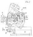
- the grinding machine is set up for grinding the handle ends 18 and 18 'of a handle 16 which is to be attached to a cylindrical vessel body.
- the two grinding units 30 are accordingly and 30 'arranged symmetrically with respect to a vertical plane of symmetry E of the grinding machine, in such a way that the axes of rotation D and D' of the grinding bodies 40 and 40 'lying in the central plane A are aligned with one another.
- the two support bodies 46 and 46 ' are arranged identically, for example - as shown in Fig. 2 with full lines - such that the axes of rotation of the drive rollers 54 and 54' in the Center plane A and thus the grinding belts 56 and 56 'extend horizontally.
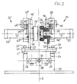
- both grinding belts 56 and 56 ' can be maintained if the grinding machine, as shown in FIG. 4, is adjusted to grind the handle ends of a handle which is to be attached to a vessel body 68 with a convex outer profile.
- the bearing blocks 32 and 32 ' are pivoted about their pivot axis C or C' in comparison with the arrangement according to FIGS. 1 to 3 such that the supporting bodies 46 diverge.
Landscapes
- Engineering & Computer Science (AREA)
- Ceramic Engineering (AREA)
- Mechanical Engineering (AREA)
- Structural Engineering (AREA)
- Chemical & Material Sciences (AREA)
- Finish Polishing, Edge Sharpening, And Grinding By Specific Grinding Devices (AREA)
Applications Claiming Priority (2)
| Application Number | Priority Date | Filing Date | Title |
|---|---|---|---|
| DE4130773 | 1991-09-16 | ||
| DE4130773A DE4130773C1 (enExample) | 1991-09-16 | 1991-09-16 |
Publications (2)
| Publication Number | Publication Date |
|---|---|
| EP0534190A1 EP0534190A1 (de) | 1993-03-31 |
| EP0534190B1 true EP0534190B1 (de) | 1995-04-26 |
Family
ID=6440725
Family Applications (1)
| Application Number | Title | Priority Date | Filing Date |
|---|---|---|---|
| EP92115080A Expired - Lifetime EP0534190B1 (de) | 1991-09-16 | 1992-09-03 | Schleifmaschine für die Enden keramischer Henkel |
Country Status (2)
| Country | Link |
|---|---|
| EP (1) | EP0534190B1 (enExample) |
| DE (2) | DE4130773C1 (enExample) |
Families Citing this family (1)
| Publication number | Priority date | Publication date | Assignee | Title |
|---|---|---|---|---|
| CN112571603B (zh) * | 2020-12-04 | 2021-12-28 | 淄博昊祥模具科技有限公司 | 陶瓷手模后处理装置 |
Citations (1)
| Publication number | Priority date | Publication date | Assignee | Title |
|---|---|---|---|---|
| DD99325A1 (enExample) * | 1972-03-17 | 1973-08-13 | Heidelberg Portland Zement |
Family Cites Families (5)
| Publication number | Priority date | Publication date | Assignee | Title |
|---|---|---|---|---|
| US2309726A (en) * | 1939-03-28 | 1943-02-02 | Onondaga Pottery Company | Trimming mechanism |
| GB565296A (en) * | 1943-09-23 | 1944-11-03 | Worcester Royal Porcelain Comp | Improvements relating to pottery manufacture |
| US2413540A (en) * | 1943-12-01 | 1946-12-31 | Swinnertons Ltd | Apparatus for trimming handles and the like for pottery goods |
| US3039163A (en) * | 1957-06-05 | 1962-06-19 | Taylor Smith & Taylor Company | Handle cutting machine |
| FR2629747B1 (fr) * | 1988-04-06 | 1991-07-26 | Bula Fils Sa | Machine de finissage de pieces moulees ou usinees |
-
1991
- 1991-09-16 DE DE4130773A patent/DE4130773C1/de not_active Expired - Fee Related
-
1992
- 1992-09-03 DE DE59202023T patent/DE59202023D1/de not_active Expired - Fee Related
- 1992-09-03 EP EP92115080A patent/EP0534190B1/de not_active Expired - Lifetime
Patent Citations (1)
| Publication number | Priority date | Publication date | Assignee | Title |
|---|---|---|---|---|
| DD99325A1 (enExample) * | 1972-03-17 | 1973-08-13 | Heidelberg Portland Zement |
Also Published As
| Publication number | Publication date |
|---|---|
| DE4130773C1 (enExample) | 1992-06-17 |
| DE59202023D1 (de) | 1995-06-01 |
| EP0534190A1 (de) | 1993-03-31 |
Similar Documents
| Publication | Publication Date | Title |
|---|---|---|
| WO2004031717A1 (de) | Rad - ausgleichsstation mit kippbarer spannvorrichtung | |
| EP0556631A1 (de) | Universal-Walzgerüst | |
| DE3225977A1 (de) | Verfahren und vorrichtung zur feinstbearbeitung konvexer oder konkaver mantelflaechen rotationssymmetrischer werkstuecke, insbesondere von waelzlagerrollen | |
| DE4023071C2 (enExample) | ||
| DE69111453T2 (de) | Vorrichtung zum schleifen, polieren usw. von werkstücken. | |
| DE1658304C3 (de) | Maschine zum Abschleifen des Schweißgrates von stumpfgeschweißten, nichtverlegten Schienen | |
| EP0534190B1 (de) | Schleifmaschine für die Enden keramischer Henkel | |
| DE2209743C3 (de) | Vorrichtung zum Abtragen von Straßenoberflächen | |
| EP0100944B1 (de) | Fördereinrichtung einer Schleuderstrahlmaschine | |
| DE2809512A1 (de) | Drehbank | |
| EP1004392B1 (de) | Schwenktisch einer Werkzeugmaschine | |
| EP0151444A2 (de) | Schleifmaschine zum Schleifen von Werkstücken, insbesondere Dekorschleifmaschine zum Schleifen von Hohlgläsern | |
| EP0484783B1 (de) | Vorrichtung zum Verspannen und Ausbalancieren von Presswerkzeugträger und Kurbelgehäuse einer Stauchpresse | |
| DE2613448A1 (de) | Vorrichtung und verfahren zum formen der kante eines schaufelelementes | |
| DE2850397A1 (de) | Profilstahl-richtmaschine | |
| AT405034B (de) | Verfahren zum automatischen polieren von flachkanten an platten aus marmor, naturstein, granit od.dgl. und automatische poliermaschine zur durchführung dieses verfahrens | |
| DE10255171A1 (de) | Maschine zum Schleifen der Kanten von hochkant stehendem Flachglas | |
| DE2350539A1 (de) | Vorrichtung zum fein- oder feinstschleifen der ballig geformten rollkoerper von waelzlagern | |
| DE503554C (de) | Vorrichtung zum Schleifen und Polieren von Fassetten an Glasplatten | |
| WO1988004972A1 (fr) | Dispositif permettant le deplacement rectiligne de pieces ou d'objets | |
| DE3401641A1 (de) | Raupenverstelleinrichtung fuer raupenabzugsmaschinen zum abziehen von extrudierten kunststoffrohren | |
| DE20020237U1 (de) | Einrichtung zur Bearbeitung der Fahrprofile der Räder eines Radsatzes | |
| AT15543B (de) | Maschine zum Spalten von Häuten, Fellen u. dgl. | |
| CH452554A (de) | Druckplatten-Spannvorrichtung für Rotationsdruckmaschinen | |
| DE3226694A1 (de) | Walzenwechselvorrichtung fuer durch verspannen auf einem umlaufenden wellenteil in fliegender anordnung als horizontalwalzen aufsitzende walzscheiben oder walzringe |
Legal Events
| Date | Code | Title | Description |
|---|---|---|---|
| PUAI | Public reference made under article 153(3) epc to a published international application that has entered the european phase |
Free format text: ORIGINAL CODE: 0009012 |
|
| 17P | Request for examination filed |
Effective date: 19921230 |
|
| AK | Designated contracting states |
Kind code of ref document: A1 Designated state(s): DE FR GB IT |
|
| 17Q | First examination report despatched |
Effective date: 19940718 |
|
| GRAA | (expected) grant |
Free format text: ORIGINAL CODE: 0009210 |
|
| ITF | It: translation for a ep patent filed | ||
| AK | Designated contracting states |
Kind code of ref document: B1 Designated state(s): DE FR GB IT |
|
| REF | Corresponds to: |
Ref document number: 59202023 Country of ref document: DE Date of ref document: 19950601 |
|
| GBT | Gb: translation of ep patent filed (gb section 77(6)(a)/1977) |
Effective date: 19950517 |
|
| ET | Fr: translation filed | ||
| PGFP | Annual fee paid to national office [announced via postgrant information from national office to epo] |
Ref country code: FR Payment date: 19950913 Year of fee payment: 4 |
|
| PGFP | Annual fee paid to national office [announced via postgrant information from national office to epo] |
Ref country code: DE Payment date: 19950926 Year of fee payment: 4 |
|
| PLBE | No opposition filed within time limit |
Free format text: ORIGINAL CODE: 0009261 |
|
| 26N | No opposition filed | ||
| PGFP | Annual fee paid to national office [announced via postgrant information from national office to epo] |
Ref country code: GB Payment date: 19960819 Year of fee payment: 5 |
|
| PG25 | Lapsed in a contracting state [announced via postgrant information from national office to epo] |
Ref country code: FR Effective date: 19960930 |
|
| PG25 | Lapsed in a contracting state [announced via postgrant information from national office to epo] |
Ref country code: DE Effective date: 19970603 |
|
| REG | Reference to a national code |
Ref country code: FR Ref legal event code: ST |
|
| REG | Reference to a national code |
Ref country code: FR Ref legal event code: ST |
|
| PG25 | Lapsed in a contracting state [announced via postgrant information from national office to epo] |
Ref country code: GB Free format text: LAPSE BECAUSE OF NON-PAYMENT OF DUE FEES Effective date: 19970903 |
|
| GBPC | Gb: european patent ceased through non-payment of renewal fee |
Effective date: 19970903 |
|
| PG25 | Lapsed in a contracting state [announced via postgrant information from national office to epo] |
Ref country code: IT Free format text: LAPSE BECAUSE OF NON-PAYMENT OF DUE FEES;WARNING: LAPSES OF ITALIAN PATENTS WITH EFFECTIVE DATE BEFORE 2007 MAY HAVE OCCURRED AT ANY TIME BEFORE 2007. THE CORRECT EFFECTIVE DATE MAY BE DIFFERENT FROM THE ONE RECORDED. Effective date: 20050903 |