EP0533495A2 - Système de commande de rapport air-carburant pour moteurs à combustion interne - Google Patents
Système de commande de rapport air-carburant pour moteurs à combustion interne Download PDFInfo
- Publication number
- EP0533495A2 EP0533495A2 EP92308543A EP92308543A EP0533495A2 EP 0533495 A2 EP0533495 A2 EP 0533495A2 EP 92308543 A EP92308543 A EP 92308543A EP 92308543 A EP92308543 A EP 92308543A EP 0533495 A2 EP0533495 A2 EP 0533495A2
- Authority
- EP
- European Patent Office
- Prior art keywords
- fuel ratio
- air
- engine
- value
- desired air
- Prior art date
- Legal status (The legal status is an assumption and is not a legal conclusion. Google has not performed a legal analysis and makes no representation as to the accuracy of the status listed.)
- Granted
Links
Images


Classifications
-
- F—MECHANICAL ENGINEERING; LIGHTING; HEATING; WEAPONS; BLASTING
- F02—COMBUSTION ENGINES; HOT-GAS OR COMBUSTION-PRODUCT ENGINE PLANTS
- F02D—CONTROLLING COMBUSTION ENGINES
- F02D41/00—Electrical control of supply of combustible mixture or its constituents
- F02D41/02—Circuit arrangements for generating control signals
- F02D41/14—Introducing closed-loop corrections
- F02D41/1438—Introducing closed-loop corrections using means for determining characteristics of the combustion gases; Sensors therefor
- F02D41/1473—Introducing closed-loop corrections using means for determining characteristics of the combustion gases; Sensors therefor characterised by the regulation method
- F02D41/1475—Regulating the air fuel ratio at a value other than stoichiometry
-
- F—MECHANICAL ENGINEERING; LIGHTING; HEATING; WEAPONS; BLASTING
- F02—COMBUSTION ENGINES; HOT-GAS OR COMBUSTION-PRODUCT ENGINE PLANTS
- F02D—CONTROLLING COMBUSTION ENGINES
- F02D41/00—Electrical control of supply of combustible mixture or its constituents
- F02D41/02—Circuit arrangements for generating control signals
- F02D41/14—Introducing closed-loop corrections
- F02D41/1438—Introducing closed-loop corrections using means for determining characteristics of the combustion gases; Sensors therefor
- F02D41/1486—Introducing closed-loop corrections using means for determining characteristics of the combustion gases; Sensors therefor with correction for particular operating conditions
-
- F—MECHANICAL ENGINEERING; LIGHTING; HEATING; WEAPONS; BLASTING
- F02—COMBUSTION ENGINES; HOT-GAS OR COMBUSTION-PRODUCT ENGINE PLANTS
- F02B—INTERNAL-COMBUSTION PISTON ENGINES; COMBUSTION ENGINES IN GENERAL
- F02B2275/00—Other engines, components or details, not provided for in other groups of this subclass
- F02B2275/18—DOHC [Double overhead camshaft]
-
- F—MECHANICAL ENGINEERING; LIGHTING; HEATING; WEAPONS; BLASTING
- F02—COMBUSTION ENGINES; HOT-GAS OR COMBUSTION-PRODUCT ENGINE PLANTS
- F02D—CONTROLLING COMBUSTION ENGINES
- F02D41/00—Electrical control of supply of combustible mixture or its constituents
- F02D41/02—Circuit arrangements for generating control signals
- F02D41/14—Introducing closed-loop corrections
- F02D41/1438—Introducing closed-loop corrections using means for determining characteristics of the combustion gases; Sensors therefor
- F02D41/1444—Introducing closed-loop corrections using means for determining characteristics of the combustion gases; Sensors therefor characterised by the characteristics of the combustion gases
- F02D41/1454—Introducing closed-loop corrections using means for determining characteristics of the combustion gases; Sensors therefor characterised by the characteristics of the combustion gases the characteristics being an oxygen content or concentration or the air-fuel ratio
- F02D41/1456—Introducing closed-loop corrections using means for determining characteristics of the combustion gases; Sensors therefor characterised by the characteristics of the combustion gases the characteristics being an oxygen content or concentration or the air-fuel ratio with sensor output signal being linear or quasi-linear with the concentration of oxygen
Definitions
- This invention relates to an air-fuel ratio control system for internal combustion engines.
- an air-fuel ratio control system for an internal combustion engine which is adapted to control the air-fuel ratio of an air-fuel mixture supplied to the engine in response to an output from an exhaust gas ingredient concentration sensor arranged in the exhaust system, the sensor having an output characteristic which is approximately proportional to the concentration of an ingredient (O2) in exhaust gases, to a desired air-fuel ratio set in response to operating conditions of the engine.
- the fuel injection period TOUT′ (and hence the fuel injection amount) is controlled by correcting a basic value thereof by various correction coefficients such that the air-fuel ratio detected by the sensor (hereinafter referred to as "the supply air-fuel ratio”) becomes equal to the desired air-fuel ratio.
- the desired air-fuel ratio depends on varying operating conditions of the engine, so that correction coefficients are calculated based on engine coolant temperature TW, intake air temperature TA, and other engine operating parameters, respectively, and a basic fuel injection period TiM (read from a predetermined map) are multiplied by these correction coefficients by the use of the following equation (1′) to calculate the fuel injection period TOUT′: where KTW represents an engine coolant temperature-dependent correction coefficient, KTA an intake air temperature-dependent correction coefficient, KWOT a high load correction coefficient, and KLAF an air-fuel ratio correction coefficient. Further, KCMDM represents a modified desired air-fuel ratio coefficient, which is generally obtained by multiplying a desired air-fuel ratio set according to the engine rotational speed NE and the intake pipe absolute pressure PBA by an air density-dependent correction coefficient KETC.
- the fuel injection period TOUT′ is calculated by multiplying the basic value TIM by numerous correction coefficients including those mentioned above, so that the fuel injection period TOUT′ may unpreferably deviate from the optimum value.
- the air-fuel ratio should desirably be accurately controlled in order to enhance the driveability, protect the engine, and reduce the fuel consumption.
- accurate air-fuel ratio control is usually accompanied by complication of maps for obtaining suitable values of correction coefficients.
- the desired air-fuel ratio is generally required to be modified in the enriching direction to secure required driveability of the engine.
- the present invention provides an air-fuel ratio control system for an internal combustion engine installed on an automotive vehicle, the engine having an exhaust passage, the system including an exhaust gas ingredient concentration sensor arranged across the exhaust passage for detecting the air-fuel ratio of an air-fuel mixture supplied to the engine, the system controlling the air-fuel ratio of the mixture to a desired air-fuel ratio set according to operating conditions of the engine, in response to an output from the exhaust gas ingredient concentration sensor.
- the air-fuel ratio control system is characterized by comprising: rotational speed-detecting means for detecting the rotational speed of the engine; load-detecting means for detecting load on the engine; first air-fuel ratio-calculating means for calculating a first value of the desired air-fuel ratio based on the engine rotational speed detected by the rotational speed-detecting means and the load on the engine detected by the load-detecting means; start-determining means for determining whether or not the vehicle has just started from a standing position thereof; second air-fuel ratio-calculating means for calculating a second value of the desired air-fuel ratio based on results of determination by the start-determining means; low temperature-determining means for determining whether or not a temperature of the engine is lower than a predetermined value; third air-fuel ratio-calculating means for calculating a third value of the desired air-fuel ratio based on results of determination by the low temperature-determining means; and setting means for setting the largest value of at least the first to third values of the desired air-fuel ratio calculated by the first to third air-fuel ratio-calculating means
- the air-fuel ratio control system further includes high-load condition determining means for determining whether or not the engine is in a predetermined high-load condition, and fourth air-fuel ratio-calculating means for calculating a fourth value of the desired air-fuel ratio, and the setting means Sets the largest value of at least the first to fourth values of the desired air-fuel ratio calculated by the first to fourth desired air-fuel ratio-calculating means to the final value of the desired air-fuel ratio.
- the air-fuel ratio control system further includes high temperature-determining means for determining whether or not the temperature of the engine is higher than a predetermined value, and fifth air-fuel ratio-calculating means for calculating a fifth value of the desired air-fuel ratio based on results of determination by the high temperature-determining means, and the setting means sets the largest value of at least the first to fifth values of the desired air-fuel ratio calculated by the first to fifth desired air-fuel ratio-calculating means to the final value of the desired air-fuel ratio.
- the temperature of the engine is the temperature of coolant of the engine.
- the air-fuel ratio control includes fuel cut-determining means for determining whether or not the supply of fuel to the engine is being cut off, measuring means for measuring a time period elapsed after resumption of fuel supply to the engine when the fuel cut determining means has determined that the supply of fuel to the engine is not being cut off, and enabling means for permitting calculation of the desired air-fuel ratio when a predetermined time period has been measured by the measuring means.
- the air-fuel ratio control system includes gear shift-determining means for determining whether or not the transmission is being gear shifted, and inhibiting means for inhibiting the first air-fuel ratio-calculating means from calculating the first value of the desired air-fuel ratio when the gear shift-determining means has determined that the transmission is being gear shifted.
- the gear shift-determining means includes load change-determining means for determining a change in load on the engine, the gear shift-determining means determining that the transmission is being shifted when the engine rotational speed detected by the rotational speed-detecting means exceeds a predetermined value, and the change in load on the engine exceeds a predetermined value.
- the gear shift-determining means includes vehicle speed-detecting means for detecting the travelling speed of the vehicle, the gear shift-determining means determining whether the transmission is being gear shifted when the travelling speed of the vehicle detected by vehicle speed-detecting means exceeds a predetermined value.
- the air-fuel ratio control system includes second measuring means for measuring a time period elapsed after termination of gear shifting of the transmission, and the inhibiting means inhibits the first air-fuel ratio-calculating means from calculating the first value of the desired air-fuel ratio before the time period measured by the second measuring means reaches a predetermined value.
- the start-determining means includes idling-determining means for determining whether or not the engine is idling.
- FIG. 1 there is shown the whole arrangement of an air-fuel ratio control system for an internal combustion engine, according to an embodiment of the invention.
- reference numeral 1 designates a DOHC straight type four cylinder engine, each cylinder being provided with a pair of intake valves and a pair of exhaust valves, not shown.
- This engine 1 is arranged such that the valve timing of the intake valves and exhaust valves can be selected between a high speed valve timing (high-speed V/T) adapted to a high engine speed region and a low speed valve timing (low-speed V/T) adapted to a low engine speed region.
- a throttle body 3 accommodating a throttle valve 3′ therein.
- a throttle valve opening ( ⁇ TH) sensor 4 is connected to the throttle valve 3′ for generating an electric signal indicative of the sensed throttle valve opening and supplying same to an electronic control unit (hereinafter referred to as "the ECU") 5.
- Fuel injection valves 6 are each provided for each cylinder and arranged in the intake pipe 2 between the engine 1 and the throttle valve 3, and at a location slightly upstream of an intake valve, not shown.
- the fuel injection valves 6 are connected to a fuel pump, not shown, and electrically connected to the ECU 5 to have their valve opening periods controlled by signals therefrom.
- an intake pipe absolute pressure (PBA) sensor 8 is mounted at an end of a branch conduit 7 branching off from the intake pipe 2 at a location immediately downstream of the throttle valve 3′, for sensing absolute pressure (PBA) within the intake pipe 2, and is electrically connected to the ECU 5 for converting the sensed absolute pressure PBA into an electric signal indicative thereof and supplying same to the ECU 5.
- PBA intake pipe absolute pressure
- An intake air temperature (TA) sensor 9 is inserted into the intake pipe 2 at a location downstream of the intake pipe absolute pressure sensor 8 for supplying an electric signal indicative of the sensed intake air temperature TA to the ECU 5.
- An engine coolant temperature (TW) sensor 10 which may be formed of a thermistor or the like, is mounted in the coolant-filled cylinder block of the engine 1 for supplying an electric signal indicative of the sensed engine coolant temperature TW to the ECU 5.
- An engine rotational speed (NE) sensor 11 and a cylinder-discriminating (CYL) sensor 12 are arranged in facing relation to a camshaft or a crankshaft of the engine 31, neither of which is shown.
- the NE sensor 11 generates a pulse as a TDC signal pulse at each of predetermined crank angles whenever the crankshaft rotates through 180 degrees, while the CYL sensor 12 generates a pulse at a predetermined crank angle of a particular cylinder of the engine, both of the pulses being supplied to the ECU 5.
- a spark plug 13 for each cylinder of the engine 1 is electrically connected to the ECU 5 to have ignition timing thereof controlled by a signal supplied therefrom.
- a transmission 14 is interposed between the engine 1 and driving wheels, not shown, to allow the driving wheels to be driven by the engine 1.
- a vehicle speed sensor (VSP) sensor 15 is provided at trailing wheels, not shown, for detecting the travelling speed VSP of the vehicle to supply an electric signal indicative of the sensed vehicle speed to the ECU 5.
- VSP vehicle speed sensor
- a linear air-fuel ratio sensor (hereinafter referred to as "the LAF sensor") 17 is arranged across an exhaust pipe 16 of the engine 1 for detecting the concentration of oxygen present in exhaust gases emitted from the engine to supply an electric signal indicative of the sensed oxygen concentration to the ECU 5.
- the output from the LAF sensor 17 is approximately proportional to the oxygen concentration.
- an electromagnetic valve 18 Connected to the output of the ECU 5 is an electromagnetic valve 18 which has the opening and closing operation thereof controlled by a signal from the ECU 5 for controlling changeover of the aforementioned valve timing of the intake and exhaust valves.
- the electromagnetic valve 18 effects changeover of hydraulic pressure prevailing within a valve timing changeover mechanism, not shown, between high and low levels, the valve timing changeover mechanism being actuated by selected level of hydraulic pressure to effect changeover of the valve timing between the high-speed V/T and the low-speed V/T.
- the hydraulic pressure within the changeover mechanism is detected by an oil pressure (POIL) sensor 19, from which an electric signal indicative of the sensed hydraulic pressure POIL is supplied to the ECU 5.
- POIL oil pressure
- the ECU 5 comprises an input circuit 5a having the functions of shaping the waveforms of input signals from various sensors as mentioned above, shifting the voltage levels of sensor output signals to a predetermined level, converting analog signals from analog-output sensors to digital signals, and so forth, a central processing unit (hereinafter referred to as "the CPU") 5b, memory means 5c formed of a ROM storing various operational programs which are executed by the CPU 5b, and various maps, referred to hereinafter, and a RAM for storing results of calculations therefrom, etc., an output circuit 5d which outputs driving signals to the fuel injection valves 6, the spark plugs 13 and the electromagnetic valve 18, respectively.
- the CPU central processing unit
- memory means 5c formed of a ROM storing various operational programs which are executed by the CPU 5b, and various maps, referred to hereinafter, and a RAM for storing results of calculations therefrom, etc.
- an output circuit 5d which outputs driving signals to the fuel injection valves 6, the spark plugs 13 and the electromagnetic valve 18, respectively.
- TiM maps used in determining the value of TiM there are stored in the memory means 5c (ROM) a TiML map suitable for the low-speed V/T and a TiMH map suitable for the high-speed V/T.
- KCMDM is a modified desired air-fuel ratio coefficient which is set by means of a program shown in Fig. 2, described hereinafter, according to engine operating conditions, and calculated by multiplying a desired air-fuel ratio coefficient KCMD representing an equivalent ratio of a desired air-fuel ratio by an air density-dependent correction coefficient KETC.
- KBS represents a basic value of the desired air-fuel ratio coefficient, which is normally read from a KBS map in which basic map values KBSM thereof are provided in a matrix associated with values of the engine rotational speed NE and those of the intake pipe absolute pressure PBA, a basic map value KBSM read from the KBS map being corrected, at standing start of the vehicle, at a low engine coolant temperature condition, or at a predetermined high-load condition, to make the basic value KBS suitable for these conditions.
- the KBS map comprises a high-speed V/T (KBSH) map for use when the high-speed V/T is selected and a low-speed V/T (KBSL) map for use when the low-speed V/T is selected, both stored in the memory means 5c (ROM).
- KBSH high-speed V/T
- KBSL low-speed V/T
- KSP is a vehicle speed-dependent correction coefficient which is set depending on the vehicle speed VSP to such a predetermined value as to prevent occurrence of surging, etc. More specifically, when the engine is under a predetermined high-load condition, it is set to a value of "1.0", and otherwise to a predetermined value through retrieval of a KSP map, described hereinafter.
- KLS represents a leaning correction coefficient which is set to predetermined values depending on operating regions of the engine.
- KDEC represents a decelerating correction coefficient which is set to a predetermined value depending on a decelerating condition of the engine. More specifically, it is set to a value smaller than "1.0" when the vehicle is decelerating, and otherwise to a value of "1.0".
- the correction coefficient KETC is intended to apply a prior correction to the fuel injection amount so as to compensate for variation of the supply air-fuel ratio due to the cooling effect produced when fuel is actually injected, and its value is set according to the value of the desired air-fuel ratio coefficient KCMD. Further, as is apparent from the aforementioned equation (1), the fuel injection period TOUT increases as the modified desired air-fuel ratio coefficient KCMDM increases, so that the modified value KCMDM of the equivalent ratio of the desired air-fuel ratio will assume a value which is in direct proportion to the reciprocal of the desired air-fuel ratio A/F.
- KLAF represents an air-fuel ratio correction coefficient, which is set, during feedback control, such that the equivalent ratio of the supply air-fuel ratio detected based on the output voltage from the LAF sensor 17 (hereinafter referred to as "the detected air-fuel ratio coefficient") KACT becomes equal to the desired air-fuel ratio coefficient KCMD, whereas during open loop control it is set to predetermined values suitable for predetermined operating conditions of the engine.
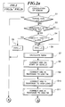
- Fig. 2 shows a main routine for calculating the modified desired air-fuel ratio coefficient KCMDM, which is executed whenever a TDC signal pulse is generated.
- step S1 it is determined whether or not the engine 1 is under fuel cut. This determination is carried out based on the engine rotational speed NE and the throttle valve opening ⁇ TH, specifically by execution of a fuel-cut condition determining routine, not shown.
- the desired air-fuel ratio coefficient KCMD is set to a predetermined value KCMDFC (e.g. 1.0) at a step S2, followed by the program proceeding to a step S13.
- a predetermined value KCMDFC e.g. 1.0
- step S3 If the answer to the question of the step S1 is negative (NO), it is determined at a step S3 whether or not the present loop is immediately after fuel cut. This determination is carried out by starting a timer upon termination of fuel cut and determining whether or not the timer has counted up its set count value corresponding to a predetermined time period, e.g. 500 millisec. If the answer to this question is affirmative (YES), i.e.
- step S4 it is determined whether or not the absolute value of the difference between the immediately preceding value KCMD (n-1) of the desired air-fuel ratio coefficient KCMD and the immediately preceding value KACT (n-1) of the detected air-fuel ratio coefficient KACT is larger than a predetermined value ⁇ KPFC (e.g. 0.14).
- the detected air-fuel ratio coefficient KACT assumes a value corrected based on the intake pipe absolute pressure PBA, the engine rotational speed NE, and the atmospheric pressure PA, in view of the fact that the pressure of exhaust gases varies with variations in these engine operating parameters.
- step S4 If the answer to the question of the step S4 is affirmative (YES), i.e. if the aforementioned difference is larger than the predetermined value ⁇ KPFC, a flag FPFC for indicating whether or not the present loop is immediately after fuel cut is set to "1" at a step S5, followed by the program proceeding to the step S2.
- the flag FPFC is set to "0"
- the desired air-fuel ratio coefficient KCMD is calculated through execution of subroutines corresponding to steps S7 to S11 depending on various operating conditions of the engine, described hereinafter.
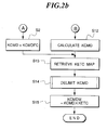
- the basic map value KBSM is calculated by retrieving the KBS map according to the engine rotational speed NE and the intake pipe absolute pressure PBA.
- step S701 it is determined at a step S701 whether or not the vehicle speed VSP detected by the VSP sensor 15 is higher than a predetermined value VX (e.g. 10 km/h). If the answer to this question is affirmative (YES), it is determined at a step S702 whether or not the engine rotational speed NE detected by the NE sensor 11 is higher than a predetermined value NEX (e.g. 900 rpm).
- VX vehicle speed
- NEX e.g. 10 km/h
- step S703 it is determined at a step S703 whether or not the difference ⁇ PBA between the immediately preceding value PBA (n-1) and the present value PBA (n) of the intake pipe absolute pressure PBA obtained by subtracting the latter from the former is larger than a predetermined value ⁇ PBX (e.g. 20 mmHg), i.e. whether or not the load on the engine has drastically shifted to a lower side.
- ⁇ PBX e.g. 20 mmHg
- a first delay timer tmDLYBS is set to a predetermined value corresponding to a predetermiried time period T1 (e.g. 300 millisec.) at a step S704, and the basic value KBS of the desired air-fuel ratio coefficient KBSM is held at the value obtained in the immediately preceding loop at a step S705.
- a flag FCH is set to "1" at a step S706 to indicate that the transmission is being gear shifted, followed by returning to the main routine of Fig. 2.
- step S707 it is determined whether or not the count value of the first delay timer tmDLYBS indicates that the predetermined time period T1 has elapsed. If the answer to this question is negative (NO), the program proceeds to the aforementioned step S705, whereas if the answer is affirmative (YES), the program proceeds to a step S708, where the flag FCH is set to "0" to indicate completion of the gear shifting of the transmission 14. Then, it is determined at a step S709 whether or not a flag FHIC has been set to "1" to indicate that the high-speed V/T has been selected.
- step S710 the KBSH map is retrieved to read a KBSM value therefrom, and then the KBSM value thus obtained is stored into the memory means 5c (RAM) at a step S711, followed by returning to the main routine of Fig. 2.
- step S709 the answer to the question of the step S709 is negative (NO), i.e.
- the program proceeds to a step S712, where the KBSL map is retrieved to read a KBSM value therefrom, and then the KBSM value read from the KBSL map is stored into the memory means 5c (RAM) at a step S713, followed by returning to the main routine of Fig. 2.
- step S8 of Fig. 2 it is determined whether or not the vehicle has just started from its standing position. If it is judged that the vehicle has just started from its standing position, the basic value KBS of the desired air-fuel ratio coefficient is corrected to a value suitable for the standing start condition of the vehicle.
- step S801 it is determined at a step S801 whether or not the flag FCH has been set to "1". If the answer to this question is affirmative (YES), i.e. if the transmission is being gear shifted, the program returns to the main routine of Fig. 2 without correcting the basic value KBS of the desired air-fuel ratio to a value suitable for the standing start condition of the vehicle.
- step S802 it is determined whether or not the engine is idling. It is determined that the engine is idling, when the engine rotational speed NE is low (e.g. lower than 900 rpm) and at the same time the throttle valve opening ⁇ TH (detected by the ⁇ TH sensor 4) assumes a value to be assumed when the engine is idling, which value is equal to or smaller than a predetermined value ⁇ idl, or when the engine rotational speed NE is low as mentioned above, and at the same time the intake pipe absolute pressure PBA (detected by the PBA sensor 8) is lower than a predetermined value, i.e. on a lower load side than the predetermined value.
- the engine rotational speed NE is low (e.g. lower than 900 rpm) and at the same time the throttle valve opening ⁇ TH (detected by the ⁇ TH sensor 4) assumes a value to be assumed when the engine is idling, which value is equal to or smaller than a predetermined
- step S802 If the answer to the question of the step S802 is affirmative (YES), the program proceeds to a step S805, whereas if it is negative (NO), the program proceeds to a step S803, where it is determined whether or not a wheel speed WP indicative of a minute value of the vehicle speed VSP is higher than a predetermined value WPX to thereby determine whether or not the vehicle can be regarded as standing.
- a second delay timer tmDLYWLF is set to a predetermine count value corresponding to a predetermined time period T2 (e.g. 100 millisec.) and started, at a step S804, followed by returning to the step S805.
- step S805 it is determined whether or not the basic value KBS, which has been set to a value read from the KBSM map at the step S711 or S713 in the subroutine of Fig. 3, or has been held to the immediately preceding value KBS (n-1) obtained in the immediately preceding loop at the step S705 in Fig. 3, is smaller than a predetermined value KBSWLF (e.g. 1.1). If the answer to this question is negative (NO), the program returns to the main routine of Fig. 2 without correcting the basic value KBS to a value suitable for the standing start condition of the vehicle, whereas if it is affirmative (YES), the KBS value is set to the predetermined value KBSWLF, followed by returning to the main routine of Fig. 2.
- a predetermined value KBSWLF e.g. 1.1
- step S803 If the answer to the question of the step S803 is affirmative (YES), i.e. if it is judged that the vehicle is not standing, the program proceeds to a step S807, where it is determined whether or not the count value of the second delay timer tmDLYWLF is equal to "0", indicating that the predetermined time period T2 has elapsed. If the answer to this question is negative (NO), it is judged that the vehicle has just started from its standing position, so that the program proceeds to the step S805, followed by returning via the step S806 to the main routine of Fig. 2.
- the program returns to the main routine of Fig. 2 without correcting the basic value KBS to the value suitable for the standing start condition of the vehicle, i.e. the predetermined value KBSWLF.
- the basic value KBS of the desired air-fuel ratio coefficient KCMD is set to a value equal to or larger (i.e. richer) than the predetermined value KBSWLF at the standing start of the vehicle.
- the basic value KBS is corrected depending on the engine coolant temperature TW in order to prevent the supply air-fuel ratio from becoming leaner when the temperature TW is low.
- a step S901 it is determined whether or not the engine coolant temperature TW is lower than a predetermined value TWL.
- the predetermined value TWL is set to a value, e.g. 70 °C, at which the supply air-fuel ratio will start to become leaner due to the low engine coolant temperature, i.e. the low temperature of the engine. If the answer to this question is affirmative (YES), i.e.
- a KTWLAF map is retrieved according to the engine coolant temperature TW and the intake pipe absolute pressure PBA to read a predetermined value KTWLAF of the basic value KBS suitable for the low engine coolant temperature condition at a step S902.
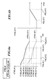
- the KTWLAF map comprises a characteristic curve KTWLAF1 (indicated by the broken line in (a) of Fig. 6) to be applied when the intake pipe absolute pressure PBA is below a predetermined value PBLAF1, and a characteristic curve KTWLAF2 (indicated by the solid line in (a) of same) to be applied when the intake pipe absolute pressure PBA is above a predetermined value PBLAF2.
- predetermined values KTWLAF11 to KTWLAF14 and KTWLAF21 to KTWLAF24 are set corresponding respectively to predetermined values TWLAF1 to TWLAF4 of the engine coolant temperature TW.
- a condition on the characteristic curve KTWLAF2 or KTWLAF1 is read from the KTWLAF map at (a) of the figure according to the engine coolant temperature (KTWLAF values corresponding to values other than the predetermined set values TWLAF1 to TWLAF4 are obtained by interpolation according to the engine coolant temperature TW), whereas if a condition of PBLAF1 ⁇ PBA ⁇ PBLAF2 is satisfied, values on the characteristic curves KTWLAF2 and KTLAF1 are read in a similar manner from (a) of the figure and the read values are subjected to interpolation according to the intake pipe absolute pressure PBA to calculate a value of KTWLAF.
- the values of KTWLAF set in the KTWLAF map are richer than a value corresponding to a stoichiometric air-fuel ratio, and by thus setting the basic value KBSM of the desired air-fuel ratio to a value of KTWLAF richer than the stoichiometric ratio, the amount of fuel supplied to the engine is increased when the engine coolant temperature is low.
- a step S903 it is determined whether or not the KBS value is smaller than the KTWLAF value obtained at the step S902. If the answer to this question is negative (NO), the program returns to the main routine of Fig. 2 without correcting the basic value KBS of the desired air-fuel ratio coefficient KCMD, whereas if the answer is affirmative (YES), the program proceeds to a step S904, where the basic value KBS is set to the KTWLAF value obtained at the step S902, followed by returning to the main routine of Fig. 2. Thus, the basic value KBS is set to a value equal to or larger than the KTWLAF value.
- the program immediately returns to the main routine without correcting the KBS value to a value suitable for the low engine coolant temperature condition, since the engine coolant temperature TW is not low.
- the basic value KBS has been set to the largest one of the immediately preceding value thereof, the KBSM value, the predetermined value KBSWLF, and the KTWLAF value.
- step S10 in Fig. 2 it is determined whether or not the engine is in a predetermined high load condition, and if the engine is in the predetermined high load condition, the basic value KBS is corrected to a value suitable for this condition of the engine.
- a step S1001 it is determined whether or not the flag FWOT has been set to "1" to thereby determine whether or not the engine is in a predetermined high load condition (e.g. the throttle valve 3′ is substantially fully opened). If the answer to this question is affirmative (YES), it is judged that the engine is in the predetermined high load condition, the program proceeds to a step S1002, where a KWOT map is retrieved to read a high-load condition map value KWOT therefrom.
- a predetermined high load condition e.g. the throttle valve 3′ is substantially fully opened
- the KWOT map has predetermined values KWOT corresponding respectively to predetermined values of the engine rotational speed NE and those of the intake pipe absolute pressure PBA, and a KWOT value is read by retrieving the KWOT map or by interpolation, if rquired.
- a high-speed V/T (KWOTH) map to be used when the high-speed V/T is in use
- a low-speed V/T (KWOTL) map to be used when the low-speed V/T is in use, both stored in the memory means 5c (ROM).
- a step S1003 it is determined whether or not the high-load condition map value KWOT thus obtained is larger than the basic value KBS. If the answer to this question is negative (NO), i.e. if KWOT ⁇ KBS, the basic value KBS is not changed but the vehicle speed-dependent correction coefficient KSP is set to "1.0" at a step S1005, followed by returning to the main routine of Fig. 2. If the answer to this question is affirmative (YES), i.e. if KWOT > KBS, the basic value KBS is set to the KWOT value at a step S1005, and then the vehicle speed-dependent correction coefficient KSP is set to "1.0" at a step S1006, followed by returning to the main routine of Fig.
- the basic value KBS is set to a value equal to or larger than the KWOT value when the engine is in the predetermined high load condition.
- the basic value KBS is set to the largest one (i.e. the richest one) of the immediately preceding value thereof, the basic map value KBSM, the predetermined value KBSWLF, the KTWLAF value, and the KWOT value.
- a KSP map is retrieved to read a vehicle speed-dependent correction coefficient KSP therefrom at a step S1007, followed by returning to the main routine of Fig. 2.
- the KSP map is set, for example, as shown in Fig. 8, which has predetermined KSP values corresponding respectively to predetermined values VSP0 to VSP3 of the vehicle speed VSP.
- a KSP value is obtained by retrieval of the KSP map or by interpolation, if required.
- the vehicle speed-dependent correction coefficient KSP is set to a larger value as the vehicle speed VSP is lower.
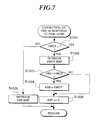
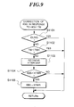
- step S11 in Fig. 2 it is determined whether or not the engine coolant temperature is high, and if it is high, the basic value KBS is corrected to a value suitable for the high engine coolant temperature condition of the engine.
- a step S1101 it is determined whether or not the engine is idling, in the same manner as described hereinbefore with reference to the step S802 in Fig. 4. If the answer to this question is affirmative (YES), the program returns to the main routine of Fig. 2, whereas if it is negative (NO), the program proceeds to a step S1102, where it is determined whether or not the engine coolant temperature TW is lower than a predetermined value TWH.
- the predetermined value TWH is set to a value, e.g. 107 °C, at which the supply air-fuel ratio will start to become enriched.
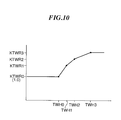
- a KTWR map is retrieved to read a predetermined value KTWR of the basic value YBS of the desired air-fuel ratio coefficient KCMD suitable for the high engine coolant temperature condition of the engine.
- the KTWR is set, for example, as shown in Fig. 10, which has predetermined KTWR values KTWR0 to KTWR3, the value of KTWR0 being set to "1.0", corresponding respectively to predetermined values TWH0 to TWH3 of the engine coolant temperature.
- a KTWR value is obtained by retrieval of the KTWR map, and by interpolation, if required. In this connection, as is apparent from Fig. 10, the value KTWR is set to a larger value as the engine coolant temperature is higher.
- a step S1104 it is determined whether or not the KBS value obtained by execution of the steps S7 to S10, described hereinbefore, is smaller than the KTWR value. If the answer to this question is negative (NO), i.e. if KBS ⁇ KTWR, the program returns to the main routine without correcting the basic value KBS, since the KBS value set heretofore is richer than the KTWR. On the other hand, if the answer to the question of the step S1104 is affirmative (YES), the basic value KBS is set to the KTWR value to obtain a corrected value suitable for the high engine temperature condition, followed by returning to the main routine of Fig. 2.
- the KBS value and the KSP value thus obtained are multiplied by the leaning correction coefficient KLS and the decelerating correction coefficient KDEC to calculate the desired air-fuel ratio coefficient KCMD (see the equation (2)).
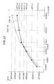
- a KETC map is retrieved to read a value of the air density-dependent correction coefficient KETC therefrom.
- the KETC map is set, for example, as shown in Fig. 11, which has predetermined KETCH values KETCH0 to KETCH6 to be selected when the engine rotational speed NE is higher than a predetermined high value (e.g. 3000 rpm), and predetermined KETCL values KETCL0 to KETCL6 to be selected when the engine rotational speed NE is lower than a predetermined low value (e.g.
- the solid line indicates a curve for the low engine rotational speed region, while the broken line a curve for the high engine rotational speed region, and the co-ordinates of the intersection (KCMD3, KETC3) assume a value of 14.7 of KCMD and a value of 1.0 of KETC.
- the KETC map is formed of different maps selected depending on the engine rotational speed, it may be formed of different maps which can be selected depending on the load on the engine.
- a limit check of the KCMD value is carried out so as to avoid too drastic a change in the coefficient KCMD by preventing the difference between the present value and the immediately preceding value of the coefficient KCMD from exceeding an upper limit value set according to operating conditions of the engine.
- the coefficient KCMD is multiplied by the KETC value to calculate the modified desired air-fuel ratio coefficient KCMDM, followed by terminating the present routine. Then, the fuel injection period TOUT is calculated by the use of the equation (1).
- the desired air-fuel ratio coefficient KCMD (and hence the modified desired air-fuel ratio KCMDM) which has been corrected in response to the standing start condition of vehicle, the low engine coolant temperature, and the high load on the engine, can be obtained by execution of a single loop of the main routine, which simplifies the process of calculation of the fuel injection time period TOUT.
- the desired air-fuel ratio coefficient KCMD can be calculated without multiplying the basic fuel injection period TiM by numerous correction coefficients as described earlier in this specification (see the equation (1′)), which enables to obtain an optimal value of the fuel injection period TOUT in a quick manner.
Applications Claiming Priority (2)
| Application Number | Priority Date | Filing Date | Title |
|---|---|---|---|
| JP3267181A JP2678985B2 (ja) | 1991-09-18 | 1991-09-18 | 内燃エンジンの空燃比制御装置 |
| JP267181/91 | 1991-09-18 |
Publications (3)
| Publication Number | Publication Date |
|---|---|
| EP0533495A2 true EP0533495A2 (fr) | 1993-03-24 |
| EP0533495A3 EP0533495A3 (en) | 1993-07-28 |
| EP0533495B1 EP0533495B1 (fr) | 1995-08-16 |
Family
ID=17441237
Family Applications (1)
| Application Number | Title | Priority Date | Filing Date |
|---|---|---|---|
| EP92308543A Expired - Lifetime EP0533495B1 (fr) | 1991-09-18 | 1992-09-18 | Système de commande de rapport air-carburant pour moteurs à combustion interne |
Country Status (5)
| Country | Link |
|---|---|
| US (1) | US5253630A (fr) |
| EP (1) | EP0533495B1 (fr) |
| JP (1) | JP2678985B2 (fr) |
| CA (1) | CA2078492C (fr) |
| DE (1) | DE69204134T2 (fr) |
Cited By (2)
| Publication number | Priority date | Publication date | Assignee | Title |
|---|---|---|---|---|
| EP0816656A2 (fr) * | 1996-06-25 | 1998-01-07 | NGK Spark Plug Co. Ltd. | Dispositif pour détecter le rapport air/carburant et pour commander le rapport air/carburant |
| GB2332069A (en) * | 1997-12-06 | 1999-06-09 | Bosch Gmbh Robert | Fuel metering based on lambda values in an internal combustion engine |
Families Citing this family (40)
| Publication number | Priority date | Publication date | Assignee | Title |
|---|---|---|---|---|
| US5445136A (en) * | 1993-06-25 | 1995-08-29 | Nippondenso Co., Ltd. | Air-fuel ratio control apparatus for internal combustion engines |
| EP0643213B1 (fr) * | 1993-09-13 | 1998-03-04 | Honda Giken Kogyo Kabushiki Kaisha | Système pour détecter le rapport air-carburant pour un moteur à combustion interne |
| JP2887056B2 (ja) * | 1993-11-12 | 1999-04-26 | 三菱電機株式会社 | 内燃機関の燃料性状判定装置 |
| DE4436085A1 (de) * | 1994-10-10 | 1996-04-11 | Daimler Benz Ag | Regelungsverfahren zur Optimierung der Schadstoffemission einer Verbrennungsanlage |
| JPH08165939A (ja) * | 1994-10-13 | 1996-06-25 | Toyota Motor Corp | 航空機用エンジンの制御装置 |
| US5566663A (en) * | 1994-10-17 | 1996-10-22 | Ford Motor Company | Air/fuel control system with improved transient response |
| US5619976A (en) * | 1995-02-24 | 1997-04-15 | Honda Giken Kogyo Kabushiki Kaisha | Control system employing controller of recurrence formula type for internal combustion engines |
| US5715796A (en) * | 1995-02-24 | 1998-02-10 | Honda Giken Kogyo Kabushiki Kaisha | Air-fuel ratio control system having function of after-start lean-burn control for internal combustion engines |
| JPH08246929A (ja) * | 1995-03-07 | 1996-09-24 | Sanshin Ind Co Ltd | エンジンの燃料噴射制御装置 |
| JP3577770B2 (ja) * | 1995-03-15 | 2004-10-13 | 日産自動車株式会社 | エンジンの空燃比制御装置 |
| DE19537786A1 (de) * | 1995-10-11 | 1997-04-17 | Bosch Gmbh Robert | Verfahren und Vorrichtung zur Steuerung einer Brennkraftmaschine |
| JP3373724B2 (ja) * | 1996-04-05 | 2003-02-04 | 本田技研工業株式会社 | 内燃機関の空燃比制御装置 |
| JP3261038B2 (ja) * | 1996-04-05 | 2002-02-25 | 本田技研工業株式会社 | 内燃機関の空燃比制御装置 |
| JP3300598B2 (ja) * | 1996-04-05 | 2002-07-08 | 本田技研工業株式会社 | 内燃機関の空燃比制御装置 |
| JP3299109B2 (ja) * | 1996-04-05 | 2002-07-08 | 本田技研工業株式会社 | スライディングモード制御方法 |
| US5852930A (en) * | 1996-04-05 | 1998-12-29 | Honda Giken Kogyo Kabushiki Kaisha | Air-fuel ratio control system for internal combustion engines |
| JP3518164B2 (ja) * | 1996-05-10 | 2004-04-12 | トヨタ自動車株式会社 | 内燃機関の空燃比制御装置 |
| JP3331161B2 (ja) * | 1996-11-19 | 2002-10-07 | 本田技研工業株式会社 | 排気ガス浄化用触媒装置の劣化判別方法 |
| JP3592519B2 (ja) * | 1997-09-16 | 2004-11-24 | 本田技研工業株式会社 | 内燃機関の排気系の空燃比制御装置及びプラントの制御装置 |
| JP3331159B2 (ja) * | 1997-09-16 | 2002-10-07 | 本田技研工業株式会社 | プラントの制御装置 |
| JP3354088B2 (ja) * | 1997-09-16 | 2002-12-09 | 本田技研工業株式会社 | 内燃機関の排気系の空燃比制御装置 |
| JP3484074B2 (ja) | 1998-05-13 | 2004-01-06 | 本田技研工業株式会社 | プラントの制御装置 |
| DE69917195T2 (de) | 1998-12-17 | 2004-09-23 | Honda Giken Kogyo K.K. | Steuersystem für das Luft/Kraftstoffverhältnis einer Brennkraftmaschine |
| JP3484088B2 (ja) | 1998-12-17 | 2004-01-06 | 本田技研工業株式会社 | プラントの制御装置 |
| JP3621839B2 (ja) | 1998-12-17 | 2005-02-16 | 本田技研工業株式会社 | プラントの制御装置 |
| JP3773684B2 (ja) | 1999-02-09 | 2006-05-10 | 本田技研工業株式会社 | 内燃機関の空燃比制御装置 |
| JP4265704B2 (ja) | 1999-04-14 | 2009-05-20 | 本田技研工業株式会社 | 内燃機関の空燃比制御装置及びプラントの制御装置 |
| JP2000310135A (ja) * | 1999-04-28 | 2000-11-07 | Honda Motor Co Ltd | 内燃機関の空燃比制御装置 |
| JP3655145B2 (ja) | 1999-10-08 | 2005-06-02 | 本田技研工業株式会社 | 多気筒内燃機関の空燃比制御装置 |
| JP3655146B2 (ja) | 1999-10-08 | 2005-06-02 | 本田技研工業株式会社 | 多気筒内燃機関の空燃比制御装置 |
| JP3688533B2 (ja) | 1999-11-12 | 2005-08-31 | 本田技研工業株式会社 | 排ガス浄化用触媒装置の劣化状態評価方法 |
| JP3782269B2 (ja) | 1999-11-12 | 2006-06-07 | 本田技研工業株式会社 | 内燃機関の空燃比制御装置 |
| JP4354068B2 (ja) | 2000-02-02 | 2009-10-28 | 本田技研工業株式会社 | 内燃機関の排ガスの空燃比制御装置 |
| MY138476A (en) | 2001-02-01 | 2009-06-30 | Honda Motor Co Ltd | Apparatus for and method of controlling plant |
| JP4437626B2 (ja) | 2001-05-14 | 2010-03-24 | 本田技研工業株式会社 | 内燃機関の空燃比制御装置 |
| JP3904923B2 (ja) | 2001-12-28 | 2007-04-11 | 本田技研工業株式会社 | 制御装置 |
| US7036982B2 (en) * | 2002-10-31 | 2006-05-02 | Delphi Technologies, Inc. | Method and apparatus to control an exhaust gas sensor to a predetermined termperature |
| US8205331B2 (en) * | 2008-01-24 | 2012-06-26 | Braly George W | Full time lean running aircraft piston engine |
| US7658184B2 (en) * | 2008-05-15 | 2010-02-09 | Lycoming Engines, a division of Avco Corportion | Method and apparatus for providing fuel to an aircraft engine |
| CN110566358B (zh) * | 2019-09-30 | 2022-03-01 | 潍柴动力股份有限公司 | 发动机起动控制方法、装置、设备及存储介质 |
Citations (6)
| Publication number | Priority date | Publication date | Assignee | Title |
|---|---|---|---|---|
| EP0136519A2 (fr) * | 1983-08-24 | 1985-04-10 | Hitachi, Ltd. | Appareil de commande du rapport air/carburant pour moteurs à combustion interne |
| JPS6267251A (ja) * | 1985-09-19 | 1987-03-26 | Honda Motor Co Ltd | 内燃エンジンの空燃比フイ−ドバツク制御方法 |
| GB2185592A (en) * | 1985-12-26 | 1987-07-22 | Honda Motor Co Ltd | Controlling air/fuel ratio of an internal combustion engine |
| JPS6321342A (ja) * | 1986-07-15 | 1988-01-28 | Toyota Motor Corp | 内燃機関の空燃比制御装置 |
| JPS63113171A (ja) * | 1986-10-30 | 1988-05-18 | Honda Motor Co Ltd | 車載内燃エンジンの空燃比制御方法 |
| DE3826573A1 (de) * | 1987-08-08 | 1989-02-16 | Mitsubishi Electric Corp | Vorrichtung zum ueberwachen des luft-/brennstoff-verhaeltnisses einer brennkraftmaschine mit innerer verbrennung |
Family Cites Families (9)
| Publication number | Priority date | Publication date | Assignee | Title |
|---|---|---|---|---|
| US4169440A (en) * | 1977-12-01 | 1979-10-02 | The Bendix Corporation | Cruise economy system |
| US4156413A (en) * | 1977-12-01 | 1979-05-29 | The Bendix Corporation | Cruise economy system |
| JPS58217749A (ja) * | 1982-06-11 | 1983-12-17 | Honda Motor Co Ltd | 内燃エンジンの特定運転状態時の燃料供給制御方法 |
| US4452207A (en) * | 1982-07-19 | 1984-06-05 | The Bendix Corporation | Fuel/air ratio control apparatus for a reciprocating aircraft engine |
| JPS6095168A (ja) * | 1983-10-31 | 1985-05-28 | Nissan Motor Co Ltd | 空燃比制御装置 |
| JPS60230532A (ja) * | 1984-04-28 | 1985-11-16 | Toyota Motor Corp | 内燃機関の空燃比制御装置 |
| JPS60233332A (ja) * | 1984-05-07 | 1985-11-20 | Toyota Motor Corp | 内燃機関の空燃比制御装置 |
| DE3808696A1 (de) * | 1988-03-16 | 1989-10-05 | Bosch Gmbh Robert | Verfahren und system zum einstellen des lambda-wertes |
| JPH0331545A (ja) * | 1989-06-27 | 1991-02-12 | Mitsubishi Automob Eng Co Ltd | 内燃機関の空燃比制御装置 |
-
1991
- 1991-09-18 JP JP3267181A patent/JP2678985B2/ja not_active Expired - Lifetime
-
1992
- 1992-09-16 US US07/945,519 patent/US5253630A/en not_active Expired - Lifetime
- 1992-09-17 CA CA002078492A patent/CA2078492C/fr not_active Expired - Fee Related
- 1992-09-18 EP EP92308543A patent/EP0533495B1/fr not_active Expired - Lifetime
- 1992-09-18 DE DE69204134T patent/DE69204134T2/de not_active Expired - Fee Related
Patent Citations (6)
| Publication number | Priority date | Publication date | Assignee | Title |
|---|---|---|---|---|
| EP0136519A2 (fr) * | 1983-08-24 | 1985-04-10 | Hitachi, Ltd. | Appareil de commande du rapport air/carburant pour moteurs à combustion interne |
| JPS6267251A (ja) * | 1985-09-19 | 1987-03-26 | Honda Motor Co Ltd | 内燃エンジンの空燃比フイ−ドバツク制御方法 |
| GB2185592A (en) * | 1985-12-26 | 1987-07-22 | Honda Motor Co Ltd | Controlling air/fuel ratio of an internal combustion engine |
| JPS6321342A (ja) * | 1986-07-15 | 1988-01-28 | Toyota Motor Corp | 内燃機関の空燃比制御装置 |
| JPS63113171A (ja) * | 1986-10-30 | 1988-05-18 | Honda Motor Co Ltd | 車載内燃エンジンの空燃比制御方法 |
| DE3826573A1 (de) * | 1987-08-08 | 1989-02-16 | Mitsubishi Electric Corp | Vorrichtung zum ueberwachen des luft-/brennstoff-verhaeltnisses einer brennkraftmaschine mit innerer verbrennung |
Non-Patent Citations (3)
| Title |
|---|
| PATENT ABSTRACTS OF JAPAN vol. 11, no. 263 (M-619)26 August 1987 & JP-A-62 067 251 ( HONDA MOTOR CO. LTD. ) 26 March 1987 * |
| PATENT ABSTRACTS OF JAPAN vol. 12, no. 227 (M-713)28 June 1988 & JP-A-63 021 342 ( TOYOTA MOTOR CORP. ) 28 January 1988 * |
| PATENT ABSTRACTS OF JAPAN vol. 12, no. 356 (M-745)26 September 1988 & JP-A-63 113 171 ( HONDA MOTOR CO. LTD. ) 18 May 1988 * |
Cited By (6)
| Publication number | Priority date | Publication date | Assignee | Title |
|---|---|---|---|---|
| EP0816656A2 (fr) * | 1996-06-25 | 1998-01-07 | NGK Spark Plug Co. Ltd. | Dispositif pour détecter le rapport air/carburant et pour commander le rapport air/carburant |
| EP0816656A3 (fr) * | 1996-06-25 | 1999-11-10 | NGK Spark Plug Co. Ltd. | Dispositif pour détecter le rapport air/carburant et pour commander le rapport air/carburant |
| US6055844A (en) * | 1996-06-25 | 2000-05-02 | Ngk Spark Plug Co., Ltd. | Air/fuel ratio detection device and an air/fuel ratio control device |
| GB2332069A (en) * | 1997-12-06 | 1999-06-09 | Bosch Gmbh Robert | Fuel metering based on lambda values in an internal combustion engine |
| GB2332069B (en) * | 1997-12-06 | 1999-11-17 | Bosch Gmbh Robert | Fuel metering signsl formation for an internal combustion engine` |
| US6029642A (en) * | 1997-12-06 | 2000-02-29 | Robert Bosch Gmbh | Method for forming a fuel-metering signal for an internal combustion engine |
Also Published As
| Publication number | Publication date |
|---|---|
| EP0533495A3 (en) | 1993-07-28 |
| JP2678985B2 (ja) | 1997-11-19 |
| CA2078492C (fr) | 1997-12-30 |
| JPH0579374A (ja) | 1993-03-30 |
| US5253630A (en) | 1993-10-19 |
| DE69204134D1 (de) | 1995-09-21 |
| CA2078492A1 (fr) | 1993-03-19 |
| DE69204134T2 (de) | 1996-05-02 |
| EP0533495B1 (fr) | 1995-08-16 |
Similar Documents
| Publication | Publication Date | Title |
|---|---|---|
| EP0533495B1 (fr) | Système de commande de rapport air-carburant pour moteurs à combustion interne | |
| US4987890A (en) | Fuel injection control system for internal combustion engine | |
| EP0691463A2 (fr) | Système de commande d'injection de carburant pour moteurs à combustion interne | |
| EP0676539B1 (fr) | Système de commande de injection de carburant pour moteur a combustion interne | |
| US5224452A (en) | Air-fuel ratio control system of internal combustion engine | |
| US5199403A (en) | Air fuel ratio control system for variable valve timing type internal combustion engines | |
| US4471742A (en) | Fuel supply control method for an internal combustion engine equipped with a supercharger | |
| US5884477A (en) | Fuel supply control system for internal combustion engines | |
| US4582036A (en) | Fuel supply control method for internal combustion engines immediately after cranking | |
| EP0163134B1 (fr) | Méthode et appareil de commande du rapport air-carburant dans un moteur à combustion interne | |
| US5661972A (en) | Air-fuel ratio control system for internal combustion engines | |
| US4597370A (en) | Method for controlling fuel supply to an internal combustion engine after termination of fuel cut | |
| EP0551207B1 (fr) | Système de commande de moteurs à combustion interne | |
| US5701871A (en) | Fuel supply control system for internal combustion engines | |
| US4589390A (en) | Air-fuel ratio feedback control method for internal combustion engines | |
| US5239963A (en) | Ignition timing control system for internal combustion engines | |
| US5690074A (en) | Fuel injection control system for internal combustion engines | |
| US4527521A (en) | Method for controlling fuel supply to an internal combustion engine after termination of fuel cut | |
| US5209213A (en) | Air-fuel ratio control method for internal combustion engines | |
| US4699111A (en) | Air-fuel ratio control method for internal combustion engines | |
| US4744345A (en) | Air-fuel ratio feedback control method for internal combustion engines | |
| US5186155A (en) | Air-fuel ratio control method for internal combustion engines | |
| EP0646709A2 (fr) | Système de commande de rapport air-carburant pour moteurs à combustion interne | |
| US5295416A (en) | Air-fuel ratio control method for internal combustion engines | |
| US5158060A (en) | Engine load parameter-calculating system and engine control system using the calculating system |
Legal Events
| Date | Code | Title | Description |
|---|---|---|---|
| PUAI | Public reference made under article 153(3) epc to a published international application that has entered the european phase |
Free format text: ORIGINAL CODE: 0009012 |
|
| AK | Designated contracting states |
Kind code of ref document: A2 Designated state(s): DE FR GB |
|
| PUAL | Search report despatched |
Free format text: ORIGINAL CODE: 0009013 |
|
| AK | Designated contracting states |
Kind code of ref document: A3 Designated state(s): DE FR GB |
|
| 17P | Request for examination filed |
Effective date: 19931204 |
|
| 17Q | First examination report despatched |
Effective date: 19941214 |
|
| GRAA | (expected) grant |
Free format text: ORIGINAL CODE: 0009210 |
|
| AK | Designated contracting states |
Kind code of ref document: B1 Designated state(s): DE FR GB |
|
| REF | Corresponds to: |
Ref document number: 69204134 Country of ref document: DE Date of ref document: 19950921 |
|
| ET | Fr: translation filed | ||
| PLBE | No opposition filed within time limit |
Free format text: ORIGINAL CODE: 0009261 |
|
| STAA | Information on the status of an ep patent application or granted ep patent |
Free format text: STATUS: NO OPPOSITION FILED WITHIN TIME LIMIT |
|
| 26N | No opposition filed | ||
| REG | Reference to a national code |
Ref country code: GB Ref legal event code: IF02 |
|
| PGFP | Annual fee paid to national office [announced via postgrant information from national office to epo] |
Ref country code: FR Payment date: 20020910 Year of fee payment: 11 |
|
| PG25 | Lapsed in a contracting state [announced via postgrant information from national office to epo] |
Ref country code: FR Free format text: LAPSE BECAUSE OF NON-PAYMENT OF DUE FEES Effective date: 20040528 |
|
| REG | Reference to a national code |
Ref country code: FR Ref legal event code: ST |
|
| PGFP | Annual fee paid to national office [announced via postgrant information from national office to epo] |
Ref country code: GB Payment date: 20060913 Year of fee payment: 15 |
|
| PGFP | Annual fee paid to national office [announced via postgrant information from national office to epo] |
Ref country code: DE Payment date: 20060914 Year of fee payment: 15 |
|
| GBPC | Gb: european patent ceased through non-payment of renewal fee |
Effective date: 20070918 |
|
| PG25 | Lapsed in a contracting state [announced via postgrant information from national office to epo] |
Ref country code: DE Free format text: LAPSE BECAUSE OF NON-PAYMENT OF DUE FEES Effective date: 20080401 |
|
| PG25 | Lapsed in a contracting state [announced via postgrant information from national office to epo] |
Ref country code: GB Free format text: LAPSE BECAUSE OF NON-PAYMENT OF DUE FEES Effective date: 20070918 |