EP0521530B1 - Toner residual amount detecting mechanism - Google Patents
Toner residual amount detecting mechanism Download PDFInfo
- Publication number
- EP0521530B1 EP0521530B1 EP92111437A EP92111437A EP0521530B1 EP 0521530 B1 EP0521530 B1 EP 0521530B1 EP 92111437 A EP92111437 A EP 92111437A EP 92111437 A EP92111437 A EP 92111437A EP 0521530 B1 EP0521530 B1 EP 0521530B1
- Authority
- EP
- European Patent Office
- Prior art keywords
- rotor
- toner
- sensor
- stirring shaft
- sensor lever
- Prior art date
- Legal status (The legal status is an assumption and is not a legal conclusion. Google has not performed a legal analysis and makes no representation as to the accuracy of the status listed.)
- Expired - Lifetime
Links
Images


Classifications
-
- G—PHYSICS
- G03—PHOTOGRAPHY; CINEMATOGRAPHY; ANALOGOUS TECHNIQUES USING WAVES OTHER THAN OPTICAL WAVES; ELECTROGRAPHY; HOLOGRAPHY
- G03G—ELECTROGRAPHY; ELECTROPHOTOGRAPHY; MAGNETOGRAPHY
- G03G15/00—Apparatus for electrographic processes using a charge pattern
- G03G15/06—Apparatus for electrographic processes using a charge pattern for developing
- G03G15/08—Apparatus for electrographic processes using a charge pattern for developing using a solid developer, e.g. powder developer
- G03G15/0822—Arrangements for preparing, mixing, supplying or dispensing developer
- G03G15/0848—Arrangements for testing or measuring developer properties or quality, e.g. charge, size, flowability
- G03G15/0856—Detection or control means for the developer level
- G03G15/0862—Detection or control means for the developer level the level being measured by optical means
-
- G—PHYSICS
- G03—PHOTOGRAPHY; CINEMATOGRAPHY; ANALOGOUS TECHNIQUES USING WAVES OTHER THAN OPTICAL WAVES; ELECTROGRAPHY; HOLOGRAPHY
- G03G—ELECTROGRAPHY; ELECTROPHOTOGRAPHY; MAGNETOGRAPHY
- G03G15/00—Apparatus for electrographic processes using a charge pattern
- G03G15/06—Apparatus for electrographic processes using a charge pattern for developing
- G03G15/08—Apparatus for electrographic processes using a charge pattern for developing using a solid developer, e.g. powder developer
- G03G15/0822—Arrangements for preparing, mixing, supplying or dispensing developer
- G03G15/0887—Arrangements for conveying and conditioning developer in the developing unit, e.g. agitating, removing impurities or humidity
- G03G15/0889—Arrangements for conveying and conditioning developer in the developing unit, e.g. agitating, removing impurities or humidity for agitation or stirring
-
- Y—GENERAL TAGGING OF NEW TECHNOLOGICAL DEVELOPMENTS; GENERAL TAGGING OF CROSS-SECTIONAL TECHNOLOGIES SPANNING OVER SEVERAL SECTIONS OF THE IPC; TECHNICAL SUBJECTS COVERED BY FORMER USPC CROSS-REFERENCE ART COLLECTIONS [XRACs] AND DIGESTS
- Y10—TECHNICAL SUBJECTS COVERED BY FORMER USPC
- Y10S—TECHNICAL SUBJECTS COVERED BY FORMER USPC CROSS-REFERENCE ART COLLECTIONS [XRACs] AND DIGESTS
- Y10S222/00—Dispensing
- Y10S222/01—Xerography
Definitions
- the present invention relates to a developing device used in a electrophotographic recording apparatus, particularly to a toner residual amount detecting mechanism of the same.
- EP 0 401 020 A2 discloses a developing device having a toner residual amount detecting mechanism wherein a sensor is adapted for detecting the rotation of a rotor rotating together with a stirring shaft in a hopper to indicate a toner supply time, said mechanism comprising a pin which is mounted in the stirring shaft, the rotor having a first end retained rotably by the stirring shaft, a second end extending adjacent to the wall of the hopper, the first end having a protrusion which is contacted with the side surface of the pin, and a sensor lever rotatably disposed outside the hopper.
- the rotor is mechanically connected with a tongue element disposed outside the hopper and the sensor lever is fixed to the stirring shaft.
- a toner residual detecting mechanism which rotates a supported stirring shaft extending in the longitudinal direction of a hopper which stores therein toner supplied thereto, transmits the resistance of the residual toner to the rotor provided on the stirring shaft, and detects the operation of the rotor by a photosensor.
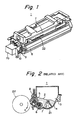
- a typical developing device is disclosed in a maintenance manual entitled "Laser LineTM 6 elite” pp 3-21 to 22, published by Oki Electric Industry Co., Ltd. in January 1988. This developing device will be described hereinafter with reference to drawings.
- Fig. 2 is a cross-sectional view of toner residual amount detecting mechanism of the developing device.
- the developing device 1 comprises a hopper portion 3 for storing toner 2 supplied thereto, a developing roller 5, a supply roller 6, and a stirring shaft 7 which extend in the longitudinal direction of the portion 3 and rotatably supported by both side portions of a frame 4, and a blade portion 8 which extends along the surface of the developing roller 5 in the axial direction thereof.
- the developing roller 5, the supply roller 6 and the stirring shaft 7 each have one end extending out of one side portion of the frame 4 and being connected to a gear.
- Each of the gears meshes an intermittent gear, not shown, to thereby form a chain of gears.
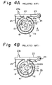
- the gear 11 coupled to the stirring shaft 7 has a stepped portion 11a and contacts a rotor 12 which rotates together with the gear 11.
- the stepped portion 11a and the rotor 12 have substantially the same radius.
- the stirring shaft 7 is fixed to the rotor 12 at one end thereof and the gear 11 is rotatable relative to the stirring shaft 7.
- the gear 11 and the rotor 12 can be rotatable relative to each other by engaging a stopper 15 provided on the gear 11 into a long slit 14 provided in the rotor 12 and engaging a protrusion 16 provided on the rotor 12 into a long slit 13 provided in the gear 11 wherein the long slits 13 and 14 are arc-shaped relative to the centers of the gear 11 and the rotor 12.
- An extension spring 18 stretches across a protrusion 17 provided on the gear 11 and the protrusion 16 provided on the rotor 12 so that the stopper 15 of the gear 11 is brought into contact with one end of the long slit 14.
- the concave portion 19 provided on the gear 11 is positioned to overlap the concave portion 20 provided on the rotor 12.
- the developing roller 5 contacts a photoconductor drum 22 as illustrated in a two dot chain line in Fig. 2.
- the stirring shaft 7 has a stirring device 21 before the toner 2 in the hopper portion 3 for preventing the toner 2 lumps in the hopper portion 3.
- Figs. 3A and 4A show the state where the toner 2 is stored in the hopper portion 3 while Figs. 3B and 4B show the state where the toner 2 is not stored in the hopper portion 3.
- a sensor lever 23 has a fulcrum 24 at one end thereof, an extension spring 25 provided at the other end thereof and a convex portion 23a provided at the substantially central portion thereof.
- the convex portion 23 of the sensor lever 23 contacts the stepped portion 11a and the outer periphery of the rotor 12 by resiliency of the extension spring 25.
- a protrusion 23b of the sensor lever 23 is retained by a microswitch 26 provided in the developing device.
- the developing roller 5 Since the gear of the developing roller 5 meshes a gear, not shown, for driving the photoconductor drum 22, the developing roller 5, the supply roller 6 and the stirring shaft 7 are rotated in the directions of the arrows B, B and D when the photoconductor drum 22 rotates in the direction of the arrow C.
- the toner 2 charged with electricity on the surface of the developing roller 5 is uniformly layered and attached thereon by the blade 8.
- the toner 2 adheres to an electrostatic latent image formed on the photoconductor drum 22 which rotates at the constant speed in the direction of the arrow C and visualizes the electrostatic latent image.
- the stirring device 21 rotates together with the stirring shaft 7 in the direction of the arrow D so that the toner 2 is conveyed to the supply roller 6 and it stirs the toner 2 for preventing the toner 2 from lumping therein.
- the resistance of the toner 2 applied to the stirring device 21 is high so that the extension spring 18 stretches as illustrated in Fig. 4A in which the rotary force of the gear 11 is transmitted to the rotor 12 to thereby rotate the stirring shaft 7 in the direction of the arrow D while the other end of the long slit 14 of the rotor 12 is in contact with the stopper 15 of the gear 11.
- the sensor lever 23 since the concave portion 20 of the gear 11 does not overlap the concave portion 19 of the rotor 12, the sensor lever 23 does not turn so that the microswitch 26 attached to the developing device does not operate.
- the resistance of the toner 2 acting on the stirring device 21 becomes weak.
- the extension spring 18 contracts and transmits the rotary force of the gear 11 to the rotor 12 while one end of the long slit 14 of the rotor 12 is in contact with the stopper 15 of the gear 11 as illustrated in Fig. 4B.
- the stirring shaft 7 is rotated in the direction of the arrow D.
- the concave portion 20 of the gear 11 overlaps the concave portion 19 of the rotor 12 so that the sensor lever 23 turns when the convex portion 23a of the same enters the concave portions 19 and 20 whereby the protrusion 23b of the sensor lever 23 operates the microswitch 26.
- the residual amount of the toner 2 in the hopper portion 3 is detected.
- the toner residual amount detecting mechanism includes a hopper, a stirring shaft, a rotor disposed respectively in the hopper, a photosensor, a pin planted on the stirring shaft and a stopper respectively disposed outside the hopper wherein the photosensor detects the rotation of the rotor together with the stirring shaft in the hopper so as to attract a sensor lever.
- the rotor formed of a magnetic body has a first end retained by the stirring shaft, a second end provided adjacent to the wall of the hopper and retained by the stirring shaft. The second end has a protrusion which contacts with the side surface of the pin.
- the sensor lever is disposed outside the hopper and has one end on which a permanent magnet is provided and is capable of turning near to the locus of the magnetic body.
- the sensor lever also turns on or off the photosensor at a bottom dead point being as a first position.
- the stopper contacts with and stops the sensor lever which turns together with the rotor to a second position wherein it turns on or off the photosensor.
- the rotor When the stirring shaft in the toner residual amount detecting mechanism is rotated, the rotor can rotate together with the stirring shaft since the one end of the pin is brought into contact with the protrusion of the rotor. When the rotor reaches the top dead point, it falls down faster than the stirring shaft by its gravity. At the time, the other end of the magnet rotor receives the resistance from the toner, depending on the presence of the toner in the hopper portion so that the stop position of the rotor is varied. As a result, the time during which the sensor lever turns the photosensor ON or OFF, is varied. It is posible to detect the accurate toner supply time by comparing this ON or OFF time with another or reference ON or OFF time. According to the invention, it is possible to detect the presence of the toner without using the spring and to provide the toner residual amount detecting mechanism capable of performing a stable operation.
- FIG. 1 is a perspective view showing the structure of a developing device provided with a toner residual amount detecting mechanism according to the present invention.
- a developing device 1 comprises a developing roller 5, gears 9 and 10, a stirring device 30 for stirring toner 2 stored in the hopper portion to prevent the toner 2 from lumping and a photo sensing mechanism 70 (not shown precisely in shape).
- the toner residual amount detecting mechanism is attached to one end of the developing apparatus 1.
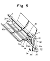
- Fig. 5 is a perspective view showing the schematic arrangement of a main portion of the toner residual amount detecting mechanism according to the first embodiment of the present invention.
- both ends of a stirring shaft 7 are rotatably supported by side portions, not shown, of a frame 4.
- One end of the stirring shaft 7 extends the outside of one side portion of the frame 4 and the other end thereof is fixed to the gear.
- a pin 31 is planted on the other end of the stirring shaft 7.
- the stirring device 30 serving as a rotor is formed of, e.g., a round iron rod and has a U-shaped configuration comprising a body 30a, arms 30b and 30c. Both ends of the arms 30b and 30c are rounded so as to be rotatable round the stirring shaft 7.
- a protrusion 30d is provided at the end of the arm 30c.
- a sensor lever 32 formed of synthetic resin etc. is light in weight and has a substantially L-shaped configuration comprising a body 32a and an arm 32b.
- the sensor lever 32 is provided outside the frame 4.
- a rotary fulcrum 33 which is provided at one end of the body 32a of the sensor lever 32 which is in parallel with the stirring shaft 7 and is turnable relative to the developing device.
- a shading portion 32c is provided at the other end of the body 32a to turn on or off a photosensor 35 fixed to the developing device.
- a stopper 36 fixed to the developing device restricts the turning range of the sensor lever 32.
- a permanent magnet 34 is embedded in the tip end of the arm 32b, and is positioned outside the frame 4.
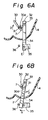
- Figs. 6A and 6B are respectively side views showing the relationship between the stirring device and the sensor lever.
- Fig. 6A shows the state where the pin 31 on the stirring shaft 7 rotates the stirring device 30 in the direction of the arrow D from the bottom dead point while the pin 31 is in contact with the protrusion 30d.
- the sensor lever 32 intercepts the light between the light emitting element and light receiving element of the photosensor 35 at the bottom dead point E, serving as the first position, to turn off the photosensor 35.
- Fig. 6B shows the state where the body 30a of the stirring device 30, which rotates in the direction of the arrow D, reaches the position closest to a permanent magnet 34 of the sensor lever 32 as illustrated in Fig.
- the sensor level 32 is turned in the direction of the arrow G and is brought into contact with the stopper 36 of the developing device since the permanent magnet 34 is attracted by the stirring device 30.
- the light receiving element receives the light emitted from the light emitting element so that the photosensor 35 turns on.
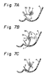
- Figs. 7A to 7C are views showing the operation of the stirring device when the toner hopper portion is empty of the toner.
- the stirring device 30 rises from the bottom dead point thereof by the rotation of the stirring shaft 7 in the direction of the arrow D while it is in contact with the pin 31.
- the stirring device 30 reaches a top dead point H and thereafter reaches the bottom dead point F by its gravity faster than the stirring shaft 7 since the amount of the toner 2 is small.
- the pin 31 of the stirring shaft 7 is brought into contact again with the stirring device 30 which has been stopped at the bottom dead point F.
- Figs. 8A and 8B are views showing the operation of the stirring device when the toner remains in the toner hopper portion.
- the stirring device 30 reaches the top dead point H and thereafter falls by its gravity to the surface of the toner 2 which remains half in a hopper portion 5.
- the stirring device 30 stirs the toner 2 by the rotation of the stirring shaft 7 in the direction of the arrow D from the state illustrated in Fig. 8A.
- Fig. 9 is a block diagram showing a structure of the control portion of the toner residual amount detecting mechanism according to the embodiment.
- a central processing unit 38 (hereinafter referred to as a CPU 38) is coupled to a memory 37 and an input/output port 39 by way of bus-lines 41 and 42.
- the photosensor 35 and an alarm lamp 40 are respectively coupled to the input/output port 39 by way of lines 43 and 44.
- the CPU 38 houses a timer 38a therein. The CPU 38 actuates the timer 38a upon reception of an OFF signal issued by the photosensor 35 so that the timer 38a counts the time until the photosensor 35 issues an ON signal.
- the CPU 38 compares a timer count value Tc counted by the timer 38a with a data Ts corresponding to the timer count value stored in the memory 37 at the time of supply of the toner and develops an alarm signal to the alarm lamp 40 when the expression of Tc ⁇ Ts is established.
- Figs. 10A and 10B are timing charts of the mechanism according to the embodiment.
- Fig. 10A shows the timing chart at the state where the toner remains in the toner hopper portion and
- Fig. 10B shows the timing chart at the time immediately before the supply of the toner.
- the time ranging from the time t 1 to t 3 shows a cycle T which represents one revolution of the stirring shaft 7 and a timer operation time T 1 ranging from the time t 1 to t 2 represents the interval during which the stirring device 30 turns the sensor lever 32 thereby turning ON the photosensor 35.
- the CPU 38 stops to actuate the timer 38a. Successively, the CPU 38 reads the timer count value Tc of the timer 38a and compares the timer count value Tc with the timer count value Ts stored in the memory at the time of supply of the toner. When the expression of Tc ⁇ Ts is established, the CPU 38 develops the alarm signal to the alarm lamp 40 to thereby light the alarm lamp 40. Supposing that the toner hopper portion is full of the toner 2 as illustrated in Figs.
- the stirring device 30 rises together with the stirring shaft 7 to the top dead point H and then rotates faster than the stirring shaft 7 by its gravity and thereafter stops at the surface of the toner 2. Successively, the stirring device 30 starts to rotate together with the stirring shaft 7 as illustrated in Fig. 8B.
- the operation at this stage is illustrated in the timing chart of Fig. 10A.
- the toner residual amount detecting mechanism completes one cycle, as illustrated in Fig. 10A, which starts at the time when the stirring device 30 rotates by its gravity from the top dead point H and ends at the time when the stirring device 30 gets over the bottom dead point E of the sensor lever 32.
- the stirring device 30 rotates by its gravity from the top dead point H as illustrated in Fig.
- the timer operation time T 1 is shortened as illustrated in Fig. 10B.
- the CPU 38 lights the alarm lamp 40 to thereby inform an operator of the need of toner.
- the rotor comprises the stirring device 30 in U-shape formed with both arms 30b and 30c as a whole, an arm 30c alone may be formed as a rotor.
- the rotor may be also provided independently of the stirring device.
- a Hall element can be used as a sensor instead of the photosensor.
- the permanent magnet should be fixed to the sensor lever.
Landscapes
- Physics & Mathematics (AREA)
- General Physics & Mathematics (AREA)
- Dry Development In Electrophotography (AREA)
Priority Applications (1)
| Application Number | Priority Date | Filing Date | Title |
|---|---|---|---|
| EP95116281A EP0704772B1 (en) | 1991-07-04 | 1992-07-06 | Toner residual amount detecting mechanism |
Applications Claiming Priority (2)
| Application Number | Priority Date | Filing Date | Title |
|---|---|---|---|
| JP164558/91 | 1991-07-04 | ||
| JP3164558A JP2837973B2 (ja) | 1991-07-04 | 1991-07-04 | トナー残量検知機構 |
Related Child Applications (1)
| Application Number | Title | Priority Date | Filing Date |
|---|---|---|---|
| EP95116281.7 Division-Into | 1992-07-06 |
Publications (3)
| Publication Number | Publication Date |
|---|---|
| EP0521530A2 EP0521530A2 (en) | 1993-01-07 |
| EP0521530A3 EP0521530A3 (ja) | 1994-04-06 |
| EP0521530B1 true EP0521530B1 (en) | 1996-10-23 |
Family
ID=15795450
Family Applications (2)
| Application Number | Title | Priority Date | Filing Date |
|---|---|---|---|
| EP92111437A Expired - Lifetime EP0521530B1 (en) | 1991-07-04 | 1992-07-06 | Toner residual amount detecting mechanism |
| EP95116281A Expired - Lifetime EP0704772B1 (en) | 1991-07-04 | 1992-07-06 | Toner residual amount detecting mechanism |
Family Applications After (1)
| Application Number | Title | Priority Date | Filing Date |
|---|---|---|---|
| EP95116281A Expired - Lifetime EP0704772B1 (en) | 1991-07-04 | 1992-07-06 | Toner residual amount detecting mechanism |
Country Status (4)
| Country | Link |
|---|---|
| US (1) | US5216462A (ja) |
| EP (2) | EP0521530B1 (ja) |
| JP (1) | JP2837973B2 (ja) |
| DE (2) | DE69222661T2 (ja) |
Families Citing this family (43)
| Publication number | Priority date | Publication date | Assignee | Title |
|---|---|---|---|---|
| US5428427A (en) * | 1992-12-14 | 1995-06-27 | Samsung Electronics Co., Ltd. | Device for detecting toner used in an electrophotography machine |
| JPH07199636A (ja) * | 1993-12-28 | 1995-08-04 | Fujitsu Ltd | トナーの残量検出装置 |
| EP0665475A3 (en) * | 1994-01-28 | 1997-01-29 | Canon Kk | Development device, process cartridge, imaging device and assembly process of the process cartridge. |
| KR0132011B1 (ko) * | 1994-02-28 | 1998-10-01 | 김광호 | 현상제 보유 레벨 검출 장치 |
| JP3263533B2 (ja) * | 1994-05-17 | 2002-03-04 | ブラザー工業株式会社 | トナー残量検出装置及びそのトナー収納装置 |
| US5630198A (en) * | 1995-12-28 | 1997-05-13 | Brother Kogyo Kabushiki Kaisha | Toner fillable cartridge having protrusions engageable with a development case shutter |
| US5995772A (en) * | 1996-02-16 | 1999-11-30 | Lexmark International Inc. | Imaging apparatus cartridge including an encoded device |
| BR9700989C1 (pt) | 1996-02-16 | 2000-04-25 | Lexmark Int Inc | Cartucho para uma máquinas eletrofotográfica |
| US5634169A (en) * | 1996-02-16 | 1997-05-27 | Lexmark International, Inc. | Multiple function encoder wheel for cartridges utilized in an electrophotographic output device |
| US5755358A (en) * | 1996-07-01 | 1998-05-26 | Xerox Corporation | Toner level detection system |
| US6130180A (en) * | 1997-12-23 | 2000-10-10 | Montell North America Inc. | Catalyst for the polymerization of alpha-olefins containing substituted amino silane compounds |
| US6100601A (en) * | 1999-08-11 | 2000-08-08 | Lexmark International, Inc. | Measurement of toner level employing sensor on paddle |
| JP3685694B2 (ja) * | 2000-08-28 | 2005-08-24 | 株式会社沖データ | トナーカートリッジと画像形成装置 |
| JP3825268B2 (ja) * | 2001-03-09 | 2006-09-27 | 株式会社沖データ | トナーカートリッジ及びトナー残量検出機構 |
| US6539182B2 (en) * | 2001-03-28 | 2003-03-25 | Heidelberger Druckmaschinen Ag | Image-forming machine having a control device for detecting toner clogging in a replenisher station |
| US6510291B2 (en) | 2001-04-19 | 2003-01-21 | Lexmark International, Inc | Toner supply with level sensor and meter and method of using the same |
| JP2006072145A (ja) * | 2004-09-03 | 2006-03-16 | Oki Data Corp | 画像形成装置 |
| US7509081B2 (en) * | 2006-12-18 | 2009-03-24 | Clarity Imaging Technologies, Inc. | High-capacity toner cartridge and toner agitator |
| US7773891B2 (en) * | 2007-10-08 | 2010-08-10 | Dell Products L.P. | System and method for determining volume of an imaging medium in a cartridge |
| JP4642086B2 (ja) * | 2008-01-23 | 2011-03-02 | 株式会社沖データ | 現像剤収容器、現像装置、及び画像形成装置 |
| JP5347332B2 (ja) * | 2008-04-15 | 2013-11-20 | 株式会社リコー | 画像形成装置 |
| JP5155280B2 (ja) * | 2009-10-30 | 2013-03-06 | 株式会社沖データ | 現像剤収容装置、トナーカートリッジ、現像装置及び画像形成装置 |
| EP2599414B1 (de) * | 2011-12-01 | 2014-05-28 | Miele & Cie. KG | Getränkebereiter |
| US9069286B2 (en) | 2012-12-18 | 2015-06-30 | Lexmark International, Inc. | Rotational sensing for a replaceable unit of an image forming device |
| US8989611B2 (en) | 2012-12-18 | 2015-03-24 | Lexmark International, Inc. | Replaceable unit for an image forming device having a falling paddle for toner level sensing |
| US9128443B2 (en) | 2012-12-18 | 2015-09-08 | Lexmark International, Inc. | Toner level sensing for replaceable unit of an image forming device |
| US9104134B2 (en) | 2012-12-18 | 2015-08-11 | Lexmark International, Inc. | Toner level sensing for replaceable unit of an image forming device |
| US9031424B2 (en) * | 2012-12-18 | 2015-05-12 | Lexmark International, Inc. | Systems and methods for measuring a particulate material |
| US9152080B2 (en) | 2012-12-18 | 2015-10-06 | Lexmark International, Inc. | Replaceable unit for an image forming device having a toner agitator that includes a magnet for rotational sensing |
| US9128444B1 (en) | 2014-04-16 | 2015-09-08 | Lexmark International, Inc. | Toner level sensing for a replaceable unit of an image forming device using pulse width patterns from a magnetic sensor |
| US9519243B2 (en) | 2014-06-02 | 2016-12-13 | Lexmark International, Inc. | Replaceable unit for an image forming device having magnets of varying angular offset for toner level sensing |
| US9335656B2 (en) | 2014-06-02 | 2016-05-10 | Lexmark International, Inc. | Toner level sensing using rotatable magnets having varying angular offset |
| US9389582B2 (en) | 2014-06-02 | 2016-07-12 | Lexmark International, Inc. | Replaceable unit for an image forming device having magnets of varying angular offset for toner level sensing |
| US9291989B1 (en) | 2015-02-25 | 2016-03-22 | Lexmark International, Inc. | Replaceable unit for an electrophotographic image forming device having an engagement member for positioning a magnetic sensor |
| US9280084B1 (en) | 2015-02-25 | 2016-03-08 | Lexmark International, Inc. | Magnetic sensor positioning by a replaceable unit of an electrophotographic image forming device |
| JP2019179072A (ja) * | 2018-03-30 | 2019-10-17 | キヤノン株式会社 | 現像剤容器、現像装置及びプロセスカートリッジ |
| JP2019179070A (ja) | 2018-03-30 | 2019-10-17 | キヤノン株式会社 | 現像剤収容容器、現像装置およびプロセスカートリッジ |
| US10429765B1 (en) | 2018-07-05 | 2019-10-01 | Lexmark International, Inc. | Toner container for an image forming device having magnets of varying angular offset for toner level sensing |
| US10474060B1 (en) | 2018-07-05 | 2019-11-12 | Lexmark International, Inc. | Toner level sensing using rotatable magnets having varying angular offset |
| US10451997B1 (en) | 2018-07-20 | 2019-10-22 | Lexmark International, Inc. | Toner level detection measuring an orientation of a rotatable magnet having a varying orientation relative to a pivot axis |
| US10345736B1 (en) | 2018-07-20 | 2019-07-09 | Lexmark International, Inc. | Toner level detection measuring a radius of a rotatable magnet |
| US10451998B1 (en) | 2018-07-20 | 2019-10-22 | Lexmark International, Inc. | Toner level detection measuring an orientation of a rotatable magnet having a varying radius |
| EP4333605A1 (en) * | 2021-05-04 | 2024-03-13 | Unverferth Manufacturing Company, Inc. | Dry product spreader |
Family Cites Families (11)
| Publication number | Priority date | Publication date | Assignee | Title |
|---|---|---|---|---|
| JPS5824786B2 (ja) * | 1974-08-13 | 1983-05-23 | 株式会社リコー | トナ−レベルケンシユツソウチ |
| JPS589170A (ja) * | 1981-07-10 | 1983-01-19 | Ricoh Co Ltd | トナ−補給装置 |
| JPS6086569A (ja) * | 1983-10-18 | 1985-05-16 | Olympus Optical Co Ltd | トナ−残量検出装置 |
| JPS60107664A (ja) * | 1983-11-16 | 1985-06-13 | Olympus Optical Co Ltd | 現像剤残量検知装置 |
| JPH0623892B2 (ja) * | 1984-04-28 | 1994-03-30 | ミノルタカメラ株式会社 | 現像剤量検出装置 |
| JPS6113267A (ja) * | 1984-06-29 | 1986-01-21 | Ricoh Co Ltd | 現像剤残量検出装置 |
| JPS6286382A (ja) * | 1985-10-11 | 1987-04-20 | Fuji Xerox Co Ltd | 複写機の現像装置 |
| JPS6319863U (ja) * | 1986-07-15 | 1988-02-09 | ||
| JP2670050B2 (ja) * | 1987-07-21 | 1997-10-29 | 株式会社リコー | 複写機の制御方法 |
| US5068691B1 (en) * | 1989-06-01 | 1995-01-24 | Fujitsu Ltd | Developing device with a controllable pressure release for the developing roller |
| US4989754A (en) * | 1989-11-30 | 1991-02-05 | Xerox Corporation | Toner level detection system |
-
1991
- 1991-07-04 JP JP3164558A patent/JP2837973B2/ja not_active Expired - Lifetime
-
1992
- 1992-07-02 US US07/907,646 patent/US5216462A/en not_active Expired - Lifetime
- 1992-07-06 DE DE69222661T patent/DE69222661T2/de not_active Expired - Lifetime
- 1992-07-06 DE DE69214731T patent/DE69214731T2/de not_active Expired - Lifetime
- 1992-07-06 EP EP92111437A patent/EP0521530B1/en not_active Expired - Lifetime
- 1992-07-06 EP EP95116281A patent/EP0704772B1/en not_active Expired - Lifetime
Also Published As
| Publication number | Publication date |
|---|---|
| DE69222661T2 (de) | 1998-04-02 |
| DE69214731D1 (de) | 1996-11-28 |
| EP0704772A1 (en) | 1996-04-03 |
| EP0521530A2 (en) | 1993-01-07 |
| US5216462A (en) | 1993-06-01 |
| JP2837973B2 (ja) | 1998-12-16 |
| JPH0511610A (ja) | 1993-01-22 |
| EP0521530A3 (ja) | 1994-04-06 |
| DE69222661D1 (de) | 1997-11-13 |
| DE69214731T2 (de) | 1997-05-28 |
| EP0704772B1 (en) | 1997-10-08 |
Similar Documents
| Publication | Publication Date | Title |
|---|---|---|
| EP0521530B1 (en) | Toner residual amount detecting mechanism | |
| EP0613066B1 (en) | Developing devices for use in electrophotographic apparatus | |
| KR100298971B1 (ko) | 전자사진출력장치에사용되는카트리지용다기능엔코더-휠 | |
| US5436704A (en) | Device for sensing the amount of residual toner of developing apparatus | |
| US4989754A (en) | Toner level detection system | |
| JPH0623892B2 (ja) | 現像剤量検出装置 | |
| BR112015012058B1 (pt) | Unidade substituível para um dispositivo de formação de imagem eletrofotográfico | |
| US4405226A (en) | Developing material supplying control device for electrostatic copying apparatus | |
| EP0044752B1 (en) | Dual component developing material detecting device for electrostatic copying apparatus | |
| JPS5824786B2 (ja) | トナ−レベルケンシユツソウチ | |
| JP3023009B2 (ja) | 光学式トナー濃度検出方法におけるトラブル検出方法 | |
| JP3373139B2 (ja) | トナ−残量検知機構 | |
| KR0181119B1 (ko) | 화상형성장치의 토너량 감지장치 | |
| JP3600116B2 (ja) | トナー補給装置 | |
| JPS5921398Y2 (ja) | 現像装置における現像剤の有無検出装置 | |
| JPS60107058A (ja) | トナ−残量検出装置 | |
| JPS6079374A (ja) | 電子複写機の現像装置 | |
| KR100602606B1 (ko) | 화상형성기의 토너엔드감지장치 | |
| JPH09265234A (ja) | トナー残量検出装置 | |
| JPH06258946A (ja) | トナー残量検出装置 | |
| JPS644173B2 (ja) | ||
| JPS62135855A (ja) | 現像剤残量検知装置 | |
| KR100279727B1 (ko) | 현상기 장착 여부 및 현상제 잔량 상태 검출장치 | |
| KR960006815B1 (ko) | 현상기의 잔류토너량 감지장치 | |
| JPH1115250A (ja) | トナー補給装置 |
Legal Events
| Date | Code | Title | Description |
|---|---|---|---|
| PUAI | Public reference made under article 153(3) epc to a published international application that has entered the european phase |
Free format text: ORIGINAL CODE: 0009012 |
|
| AK | Designated contracting states |
Kind code of ref document: A2 Designated state(s): DE FR GB |
|
| PUAL | Search report despatched |
Free format text: ORIGINAL CODE: 0009013 |
|
| AK | Designated contracting states |
Kind code of ref document: A3 Designated state(s): DE FR GB |
|
| 17P | Request for examination filed |
Effective date: 19940615 |
|
| 17Q | First examination report despatched |
Effective date: 19950609 |
|
| GRAG | Despatch of communication of intention to grant |
Free format text: ORIGINAL CODE: EPIDOS AGRA |
|
| GRAH | Despatch of communication of intention to grant a patent |
Free format text: ORIGINAL CODE: EPIDOS IGRA |
|
| GRAH | Despatch of communication of intention to grant a patent |
Free format text: ORIGINAL CODE: EPIDOS IGRA |
|
| GRAA | (expected) grant |
Free format text: ORIGINAL CODE: 0009210 |
|
| AK | Designated contracting states |
Kind code of ref document: B1 Designated state(s): DE FR GB |
|
| XX | Miscellaneous (additional remarks) |
Free format text: TEILANMELDUNG 95116281.7 EINGEREICHT AM 16/10/95. |
|
| REF | Corresponds to: |
Ref document number: 69214731 Country of ref document: DE Date of ref document: 19961128 |
|
| ET | Fr: translation filed | ||
| PLBE | No opposition filed within time limit |
Free format text: ORIGINAL CODE: 0009261 |
|
| STAA | Information on the status of an ep patent application or granted ep patent |
Free format text: STATUS: NO OPPOSITION FILED WITHIN TIME LIMIT |
|
| 26N | No opposition filed | ||
| REG | Reference to a national code |
Ref country code: GB Ref legal event code: IF02 |
|
| PGFP | Annual fee paid to national office [announced via postgrant information from national office to epo] |
Ref country code: FR Payment date: 20110727 Year of fee payment: 20 |
|
| PGFP | Annual fee paid to national office [announced via postgrant information from national office to epo] |
Ref country code: GB Payment date: 20110706 Year of fee payment: 20 Ref country code: DE Payment date: 20110629 Year of fee payment: 20 |
|
| REG | Reference to a national code |
Ref country code: DE Ref legal event code: R071 Ref document number: 69214731 Country of ref document: DE |
|
| REG | Reference to a national code |
Ref country code: DE Ref legal event code: R071 Ref document number: 69214731 Country of ref document: DE |
|
| REG | Reference to a national code |
Ref country code: GB Ref legal event code: PE20 Expiry date: 20120705 |
|
| PG25 | Lapsed in a contracting state [announced via postgrant information from national office to epo] |
Ref country code: DE Free format text: LAPSE BECAUSE OF EXPIRATION OF PROTECTION Effective date: 20120707 Ref country code: GB Free format text: LAPSE BECAUSE OF EXPIRATION OF PROTECTION Effective date: 20120705 |