EP0521530A2 - Toner residual amount detecting mechanism - Google Patents
Toner residual amount detecting mechanism Download PDFInfo
- Publication number
- EP0521530A2 EP0521530A2 EP92111437A EP92111437A EP0521530A2 EP 0521530 A2 EP0521530 A2 EP 0521530A2 EP 92111437 A EP92111437 A EP 92111437A EP 92111437 A EP92111437 A EP 92111437A EP 0521530 A2 EP0521530 A2 EP 0521530A2
- Authority
- EP
- European Patent Office
- Prior art keywords
- rotor
- stirring shaft
- toner
- residual amount
- amount detecting
- Prior art date
- Legal status (The legal status is an assumption and is not a legal conclusion. Google has not performed a legal analysis and makes no representation as to the accuracy of the status listed.)
- Granted
Links
Images


Classifications
-
- G—PHYSICS
- G03—PHOTOGRAPHY; CINEMATOGRAPHY; ANALOGOUS TECHNIQUES USING WAVES OTHER THAN OPTICAL WAVES; ELECTROGRAPHY; HOLOGRAPHY
- G03G—ELECTROGRAPHY; ELECTROPHOTOGRAPHY; MAGNETOGRAPHY
- G03G15/00—Apparatus for electrographic processes using a charge pattern
- G03G15/06—Apparatus for electrographic processes using a charge pattern for developing
- G03G15/08—Apparatus for electrographic processes using a charge pattern for developing using a solid developer, e.g. powder developer
- G03G15/0822—Arrangements for preparing, mixing, supplying or dispensing developer
- G03G15/0848—Arrangements for testing or measuring developer properties or quality, e.g. charge, size, flowability
- G03G15/0856—Detection or control means for the developer level
- G03G15/0862—Detection or control means for the developer level the level being measured by optical means
-
- G—PHYSICS
- G03—PHOTOGRAPHY; CINEMATOGRAPHY; ANALOGOUS TECHNIQUES USING WAVES OTHER THAN OPTICAL WAVES; ELECTROGRAPHY; HOLOGRAPHY
- G03G—ELECTROGRAPHY; ELECTROPHOTOGRAPHY; MAGNETOGRAPHY
- G03G15/00—Apparatus for electrographic processes using a charge pattern
- G03G15/06—Apparatus for electrographic processes using a charge pattern for developing
- G03G15/08—Apparatus for electrographic processes using a charge pattern for developing using a solid developer, e.g. powder developer
- G03G15/0822—Arrangements for preparing, mixing, supplying or dispensing developer
- G03G15/0887—Arrangements for conveying and conditioning developer in the developing unit, e.g. agitating, removing impurities or humidity
- G03G15/0889—Arrangements for conveying and conditioning developer in the developing unit, e.g. agitating, removing impurities or humidity for agitation or stirring
-
- Y—GENERAL TAGGING OF NEW TECHNOLOGICAL DEVELOPMENTS; GENERAL TAGGING OF CROSS-SECTIONAL TECHNOLOGIES SPANNING OVER SEVERAL SECTIONS OF THE IPC; TECHNICAL SUBJECTS COVERED BY FORMER USPC CROSS-REFERENCE ART COLLECTIONS [XRACs] AND DIGESTS
- Y10—TECHNICAL SUBJECTS COVERED BY FORMER USPC
- Y10S—TECHNICAL SUBJECTS COVERED BY FORMER USPC CROSS-REFERENCE ART COLLECTIONS [XRACs] AND DIGESTS
- Y10S222/00—Dispensing
- Y10S222/01—Xerography
Definitions
- the present invention relates to a developing device used in a electrophotographic recording apparatus, particularly to a toner residual amount detecting mechanism of the same.
- a toner residual detecting mechanism which rotates a supported stirring shaft extending in the longitudinal direction of a hopper which stores therein toner supplied thereto, transmits the resistance of the residual toner to the rotor provided on the stirring shaft, and detects the operation of the rotor by a photosensor.
- a typical developing device is disclosed in a maintenance manual entitled "Laser Line TM 6 elite” pp 3-21 to 22, published by Oki Electric Industry Co., Ltd. in January 1988. This developing device will be described hereinafter with reference to drawings.
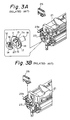
- Fig. 2 is a cross-sectional view of toner residual amount detecting mechanism of the developing device.
- the developing device 1 comprises a hopper portion 3 for storing toner 2 supplied thereto, a developing roller 5, a supply roller 6, and a stirring shaft 7 which extend in the longitudinal direction of the portion 3 and rotatably supported by both side portions of a frame 4, and a blade portion 8 which extends along the surface of the developing roller 5 in the axial direction thereof.
- the developing roller 5, the supply roller 6 and the stirring shaft 7 each have one end extending out of one side portion of the frame 4 and being connected to a gear.
- Each of the gears meshes an intermittent gear, not shown, to thereby form a chain of gears.
- the gear 11 coupled to the stirring shaft 7 has a stepped portion 11a and contacts a rotor 12 which rotates together with the gear 11.
- the stepped portion 11a and the rotor 12 have substantially the same radius.
- the stirring shaft 7 is fixed to the rotor 12 at one end thereof and the gear 11 is rotatable relative to the stirring shaft 7.
- the gear 11 and the rotor 12 can be rotatable relative to each other by engaging a stopper 15 provided on the gear 11 into a long slit 14 provided in the rotor 12 and engaging a protrusion 16 provided on the rotor 12 into a long slit 13 provided in the gear 11 wherein the long slits 13 and 14 are arc-shaped relative to the centers of the gear 11 and the rotor 12.
- An extension spring 18 stretches across a protrusion 17 provided on the gear 11 and the protrusion 16 provided on the rotor 12 so that the stopper 15 of the gear 11 is brought into contact with one end of the long slit 14.
- the concave portion 19 provided on the gear 11 is positioned to overlap the concave portion 20 provided on the rotor 12.
- the developing roller 5 contacts a photoconductor drum 22 as illustrated in a two dot chain line in Fig. 2.
- the stirring shaft 7 has a stirring device 21 before the toner 2 in the hopper portion 3 for preventing the toner 2 lumps in the hopper portion 3.
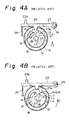
- Figs. 3A and 4A show the state where the toner 2 is stored in the hopper portion 3 while Figs. 3B and 4B show the state where the toner 2 is not stored in the hopper portion 3.
- a sensor lever 23 has a fulcrum 24 at one end thereof, an extension spring 25 provided at the other end thereof and a convex portion 23a provided at the substantially central portion thereof.
- the convex portion 23 of the sensor lever 23 contacts the stepped portion 11a and the outer periphery of the rotor 12 by resiliency of the extension spring 25.
- a protrusion 23b of the sensor lever 23 is retained by a microswitch 26 provided in the developing device.
- the developing roller 5 Since the gear of the developing roller 5 meshes a gear, not shown, for driving the photoconductor drum 22, the developing roller 5, the supply roller 6 and the stirring shaft 7 are rotated in the directions of the arrows B, B and D when the photoconductor drum 22 rotates in the direction of the arrow C.
- the toner 2 charged with electricity on the surface of the developing roller 5 is uniformly layered and attached thereon by the blade 8.
- the toner 2 adheres to an electrostatic latent image formed on the photoconductor drum 22 which rotates at the constant speed in the direction of the arrow C and visualize the electrostatic latent image.
- the stirring device 21 rotates together with the stirring shaft 7 in the direction of the arrow D so that the toner 2 is conveyed to the supply roller 6 and it stirs the toner 2 for preventing the toner 2 from lumping therein.
- the resistance of the toner 2 applied to the stirring device 21 is high so that the extension spring 18 stretches as illustrated in Fig. 4A in which the rotary force of the gear 11 is transmitted to the rotor 12 to thereby rotate the stirring shaft 7 in the direction of the arrow D while the other end of the long slit 14 of the rotor 12 is in contact with the stopper 15 of the gear 11.
- the sensor lever 23 since the concave portion 20 of the gear 11 does not overlap the concave portion 19 of the rotor 12, the sensor lever 23 does not turn so that the microswitch 26 attached to the developing device does not operate.
- the resistance of the toner 2 acting on the stirring device 21 becomes weak.
- the extension spring 18 contracts and transmits the rotary force of the gear 11 to the rotor 12 while one end of the long slit 14 of the rotor 12 is in contact with the stopper 15 of the gear 11 as illustrated in Fig. 4B.
- the stirring shaft 7 is rotated in the direction of the arrow D.
- the concave portion 20 of the gear 11 overlaps the concave portion 19 of the rotor 12 so that the sensor lever 23 turns when the convex portion 23a of the same enters the concave portions 19 and 20 whereby the protrusion 23b of the sensor lever 23 operates the microswitch 26.
- the residual amount of the toner 2 in the hopper portion 3 is detected.
- the toner residual amount detecting mechanism includes a hopper, a stirring shaft, a rotor disposed respectively in the hopper, a photosensor, a pin planted on the stirring shaft and a stopper respectively disposed outside the hopper wherein the photosensor detects the rotation of the rotor together with the stirring shaft in the hopper so as to attract a sensor lever.
- the rotor formed of a magnetic body has a first end retained by the stirring shaft, a second end provided adjacent to the wall of the hopper and retained by the stirring shaft. The second end has a protrusion which contacts with the side surface of the pin.
- the sensor lever is disposed outside the hopper and has one end on which a permanent magnet is provided and is capable of turning near to the locus of the magnetic body.
- the sensor lever also turns on or off the photosensor at a bottom dead point being as a first position.
- the stopper contacts with and stops the sensor lever which turns together with the rotor to a second position wherein it turns on or off the photosensor.
- the rotor When the stirring shaft in the toner residual amount detecting mechanism is rotated, the rotor can rotate together with the stirring shaft since the one end of the pin brought into contact with the protrusion of the rotor. When the rotor reaches the top dead point, it falls down faster than the stirring shaft by its gravity. At the time. the other end of the magnet rotor receives the resistance from the toner, depending on the presence of the toner in the hopper portion so that the stop position of the rotor is varied. As a result, the time during which the sensor lever turns the photosensor ON or OFF, is varied. It is possible to detect the accurate toner supply time by comparing this ON or OFF time with another or reference ON or OFF time. According to the first aspect of the present invention, it is possible to detect the presence of the toner without using the spring and to provide the toner residual amount detecting mechanism capable of performing a stable operation.
- the toner residual amount detecting mechanism comprises a stirring shaft, a guide pin disposed on the central portion of the stirring shaft crossing the stirring shaft at right angles thereto, a rotor having a C-shape in cross section and extending in the axial direction of the stirring shaft, the rotor having a slot provided in the circumferential direction of the central portion thereof, the slot being freely engaged with one end of the guide pin so as to constitute a turning pair together with the stirring shaft, a reset spring extending in the axial direction of the stirring shaft and having both ends respectively slidably held by both ends of the rotor and a central portion which brings into contact with the peripheral surface of the other end of the guide pin so as to bias the rotor and cause one end of the slot to bring into contact with one end of the guide pin, and an actuator having one end fixed to a sensor shaft which is rotatably supported in parallel with the stirring shaft and another end extending toward the stirring shaft so as to cross the stirring shaft and being in contact
- the rotor rotated together with the stirring shaft receives the resistance from the toner and rotates against the resiliency of the reset spring until it is contacted with the one end of the slot along the one end of the guide pin.
- the other end of the guide pin is positioned on the chord side of the crescent-shaped rotor. Since the other end of the actuator is brought into contact with the rotor and the other end of the guide pin during one revolution of the stirring shaft, the actuator cannot turn so that the sensor shaft coupled to the actuator cannot turn on or off the photosensor.
- the rotor does not turn since it does not receive the resistance from the toner, whereby the guide pin is in parallel with the chord of the crescent-shaped rotor.
- the rotor turns so that the sensor shaft coupled to the actuator turns on or off the photosensor since the actuator is not impeded in the turning thereof by the rotor and the guide pin. Accordingly, it is possible to detect the toner supply time.
- the spring can stretch in the axial direction of the stirring shaft, the spring constant can be set in conformity with the resistance of the toner. As a result. it is possible to provide the toner residual amount detecting mechanism capable of performing the stable operation.
- FIG. 1 is a perspective view showing the structure of a developing device provided with a toner residual amount detecting mechanism according to the present invention.
- a developing device 1 comprises a developing roller 5, gears 9 and 10, a stirring device 30 for stirring toner 2 stored in the hopper portion to prevent the toner 2 from lumping and a photo sensing mechanism 70 (not shown precisely in shape).
- the toner residual amount detecting mechanism is attached to one end of the developing apparatus 1.
- a toner residual amount detecting mechanism according to the first embodiment will be described with reference to Figs. 5 to 10.
- Fig. 5 is a perspective view showing the schematic arrangement of a main portion of the toner residual amount detecting mechanism according to the first embodiment of the present invention.
- both ends of a stirring shaft 7 are rotatably supported by side portions, not shown, of a frame 4.
- One end of the stirring shaft 7 extends the outside of one side portion of the frame 4 and the other end thereof is fixed to the gear.
- a pin 31 is planted on the other end of the stirring shaft 7.
- the stirring device 30 serving as a rotor is formed of, e.g., a round iron rod and has a U-shaped configuration comprising a body 30a, arms 30b and 30c. Both ends of the arms 30b and 30c are rounded so as to be rotatable round the stirring shaft 7.
- a protrusion 30d is provided at the end of the arm 30c.
- a sensor lever 32 formed of synthetic resin etc. is light in weight and has a substantially L-shaped configuration comprising a body 32a and an arm 32b.
- the sensor lever 32 is provided outside the frame 4.
- a rotary fulcrum 33 which is provided at one end of the body 32a of the sensor lever 32 which is in parallel with the stirring shaft 7 and is turnable relative to the developing device.
- a shading portion 32c is provided at the other end of the body 32a to turn on or off a photosensor 35 fixed to the developing device.
- a stopper 36 fixed to the developing device restricts the turning range of the sensor lever 32.
- a permanent magnet 34 is embedded in the tip end of the arm 32b, and is positioned outside the frame 4.
- Figs. 6A and 6B are respectively side views showing the relationship between the stirring device and the sensor lever.
- Fig. 6A shows the state where the pin 31 on the stirring shaft 7 rotates the stirring device 30 in the direction of the arrow D from the bottom dead point while the pin 31 is in contact with the protrusion 30d.
- the sensor lever 32 intercepts the light between the light emitting element and light receiving element of the photosensor 35 at the bottom dead point E, serving as the first position, to turn off the photosensor 35.
- Fig. 6B shows the state where the body 30a of the stirring device 30, which rotates in the direction of the arrow D, reaches the position closest to a permanent magnet 34 of the sensor lever 32 as illustrated in Fig.
- the sensor lever 32 is turned in the direction of the arrow G and is brought into contact with the stopper 36 of the developing device since the permanent magnet 34 is attracted by the stirring device 30.
- the light receiving element receives the light emitted from the light emitting element so that the photosensor 35 turns on.
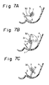
- Figs. 7A to 7C are views showing the operation of the stirring device when the toner hopper portion is empty of the toner.
- the stirring device 30 rises from the bottom dead point thereof by the rotation of the stirring shaft 7 in the direction of the arrow D while it is in contact with the pin 31.
- the stirring device 30 reaches a top dead point H and thereafter reaches the bottom dead point F by its gravity faster than the stirring shaft 7 since the amount of the toner 2 is small.
- the pin 31 of the stirring shaft 7 is brought into contact again with the stirring device 30 which has been stopped at the bottom dead point F.
- Figs. 8A and 8B are views showing the operation of the stirring device when the toner remains in the toner hopper portion.
- the stirring device 30 reaches the top dead point H and thereafter falls by its gravity to the surface of the toner 2 which remains half in a hopper portion 5.
- the stirring device 30 stirs the toner 2 by the rotation of the stirring shaft 7 in the direction of the arrow D from the state illustrated in Fig. 8A.
- Fig. 9 is a block diagram showing a structure of the control portion of the toner residual amount detecting mechanism according to the first embodiment.
- a central processing unit 38 (hereinafter referred to as a CPU 38) is coupled to a memory 37 and an input/output port 39 by way of bus-lines 41 and 42.
- the photosensor 35 and an alarm lamp 40 are respectively coupled to the input/output port 39 by way of lines 43 and 44.
- the CPU 38 houses a timer 38a therein. The CPU 38 actuates the timer 38a upon reception of an OFF signal issued by the photosensor 35 so that the timer 38a counts the time until the photosensor 35 issues an ON signal.
- the CPU 38 compares a timer count value Tc counted by the timer 38a with a data Ts corresponding to the timer count value stored in the memory 37 at the time of supply of the toner and develops an alarm signal to the alarm lamp 40 when the expression of Tc ⁇ Ts is established.
- Figs. 10A and 10B are timing charts of the mechanism according to the first embodiment.
- Fig. 10A shows the timing chart at the state where the toner remains in the toner hopper portion and
- Fig. 10B shows the timing chart at the time immediately before the supply of the toner.
- the time ranging from the time t1 to t3 shows a cycle T which represents one revolution of the stirring shaft 7 and a timer operation time T1 ranging from the time t1 to t2 represents the interval during which the stirring device 30 turns the sensor lever 32 thereby turning ON the photosensor 35.
- the CPU 38 stops to actuate the timer 38a. Successively, the CPU 38 reads the timer count value Tc of the timer 38a and compares the timer count value Tc with the timer count value Ts stored in the memory at the time of supply of the toner. When the expression of Tc ⁇ Ts is established, the CPU 38 develops the alarm signal to the alarm lamp 40 to thereby light the alarm lamp 40. Supposing that the toner hopper portion is full of the toner 2 as illustrated in Figs.
- the stirring device 30 rises together with the stirring shaft 7 to the top dead point H and then rotates faster than the stirring shaft 7 by its gravity and thereafter stops at the surface of the toner 2. Successively, the stirring device 30 starts to rotate together with the stirring shaft 7 as illustrated in Fig. 8B.
- the operation at this stage is illustrated in the timing chart of Fig. 10A.
- the toner residual amount detecting mechanism completes one cycle, as illustrated in Fig. 10A, which starts at the time when the stirring device 30 rotates by its gravity from the top dead point H and ends at the time when the stirring device 30 gets over the bottom dead point E of the sensor lever 32.
- the stirring device 30 rotates by its gravity from the top dead point H as illustrated in Fig.
- the timer operation time T1 is shortened as illustrated in Fig. 10B.
- the CPU 38 lights the alarm lamp 40 to thereby inform an operator of the need of toner.
- the rotor comprises the stirring device 30 in U-shape formed with both arms 30b and 30c as a whole, an arm 30c alone may be formed as a rotor.
- the rotor may be also provided independently of the stirring device.
- a Hall element can be used as a sensor instead of the photosensor.
- the permanent magnet should be fixed to the sensor lever.
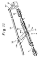
- Fig. 11 is a perspective view showing a schematic arrangement of the main portion of the toner residual amount detecting mechanism according to the second embodiment of the present invention.
- a sensor shaft 53 is rotatably supported by the side portion of the frame 4 and disposed in parallel with the stirring shaft 7.
- a guide pin 51 penetrates the central portion of the stirring shaft 7 so as to make a cross.
- a sensor member 50 as a rotor is turnably provided at the central portion of the stirring shaft 7 while the guide pin 51 serves as the guide for the sensor member 50.
- a reset spring 52 has both ends slidably supported by both ends of the sensor member 50 and a central flexible portion which is in contact with one end 51a of the guide pin 51. That is, when the sensor member 50 turns in the direction of the arrow I, the reset spring 52 twists and flexes so as to return the sensor member 50 in the direction of the arrow J.
- An actuator 54 has one end 54a which is fixed to the sensor shaft 53 and the other end 54b which is in contact with the central portion of the sensor member 50.
- a sensor lever 60 is fixed to one end of the center shaft 53 which extends out of the hopper and turns on and off a photosensor 61 in response to the rotation of the actuator 54.
- Fig. 12 is a perspective view of the sensor member 50 as viewed from the direction of the arrow K in Fig. 11.
- the sensor member 50 includes a central portion 55, both ends 56 and 57 and arms 58.
- the arms 58 for coupling the central portion 55 with the both ends 56 and 57 are disposed symmetrically with each other relative to the stirring shaft 7.
- the central portion 55 and both ends 56 and 57 have C-shapes in cross section.
- a slot 59 is provided at the central portion 55 so as to guide rotatably the other end 51b of the guide pin 51.
- the central portion 55 constitute a turning pair together with the stirring shaft 7.
- the other end 51b of the guide pin 51 is brought into contact with one end 59a of the slot 59 when it is reset by resiliency of the reset spring 52.
- the sensor member 50 When the sensor member 50 is rotated together with the stirring shaft 7, it receives the resistance of the toner so that the other end 51b of the guide pin 51 is brought into contact with the other end 59b of the slot 59.
- Figs. 13A to 13D are views showing the operation of the mechanism when the hopper portion is full of the toner and the sensor member turns half in the direction of the arrow J.
- Fig. 13A shows the state where the other end 54b of the actuator 54 is in contact with the other end 51b of the guide pin 51 so that the photosensor 61 is OFF.
- Fig. 13B shows the state where the other end 54b of the actuator 54 is in contact with the sensor member 50.
- Fig. 13C shows the state where the other end 54b of the actuator 54 is in contact with one end 51a of the guide pin 51.
- a two dot chain line shows that the other end 54b of the actuator 54 is in the state as illustrated in Fig. 13B.
- Fig. 13A shows the state where the other end 54b of the actuator 54 is in contact with the other end 51b of the guide pin 51 so that the photosensor 61 is OFF.
- Fig. 13B shows the state where the other end 54b of the actuator 54 is in contact with the sensor
- FIG. 13D shows the state where the other end 54b of the actuator 54 is in contact with one end 51a of the guide pin 51. Successively, the other end 54b of the actuator 54 is in contact with a circular portion of the sensor member 50 and thereafter returns to the state as illustrated in Fig. 13A. That is, since the other end 54b of the actuator 54 does not turn to reach the bottom dead point, the sensor shaft 53 does not turn ON the photosensor 61.
- Figs. 14A to 14C are views showing the operation of the mechanism that when the toner hopper portion is empty of the toner, the sensor member turns half in the direction of the arrow J.
- Fig. 14A shows the same state as that in Fig. 13A.
- Fig. 14B shows the state where the other end 54b of the actuator 54 turns to reach the bottom dead point to thereby turn ON the photosensor 61.
- Fig. 14C shows the state where the actuator 54 which had turned to reach the bottom dead center was again brought into contact with one end 51a of the guide pin 51 and thereafter has returned to the position as illustrated in Fig. 14A. Thereafter, the other end 54b of the actuator 54 is brought into contact with the circular portion of the sensor member 50 and returns to the state as illustrated in Fig. 14A.
- the sensor member according to the second embodiment operates not only to detect the residual amount of the toner but to stir the toner.
- the width of the actuator is substantially same as the width of the central portion of the sensor member.
- a stirring bar 63 may be provided at the other end 62b of an actuator 62 which is arranged over the whole length of the sensor member as illustrated in Fig. 15. In this case, when the actuator 62 moves up and down in accordance with the rotation of the sensor member, the stirring bar 63 collapses the toner located adjacent to the sensor member 50 whereby the toner is prevented from hollowing around the periphery of the sensor member 50.
Abstract
Description
- The present invention relates to a developing device used in a electrophotographic recording apparatus, particularly to a toner residual amount detecting mechanism of the same.
- Conventionally some developing devices used in the electrophotographic apparatus are provided with a toner residual detecting mechanism, which rotates a supported stirring shaft extending in the longitudinal direction of a hopper which stores therein toner supplied thereto, transmits the resistance of the residual toner to the rotor provided on the stirring shaft, and detects the operation of the rotor by a photosensor. For example, such a typical developing device is disclosed in a maintenance manual entitled "Laser Line ™ 6 elite" pp 3-21 to 22, published by Oki Electric Industry Co., Ltd. in January 1988. This developing device will be described hereinafter with reference to drawings.
- Fig. 2 is a cross-sectional view of toner residual amount detecting mechanism of the developing device.
- The developing
device 1 comprises ahopper portion 3 for storingtoner 2 supplied thereto, a developingroller 5, a supply roller 6, and astirring shaft 7 which extend in the longitudinal direction of theportion 3 and rotatably supported by both side portions of aframe 4, and a blade portion 8 which extends along the surface of the developingroller 5 in the axial direction thereof. The developingroller 5, the supply roller 6 and thestirring shaft 7 each have one end extending out of one side portion of theframe 4 and being connected to a gear. Each of the gears meshes an intermittent gear, not shown, to thereby form a chain of gears. As illustrated in Fig. 3A, thegear 11 coupled to the stirringshaft 7 has astepped portion 11a and contacts arotor 12 which rotates together with thegear 11. Thestepped portion 11a and therotor 12 have substantially the same radius. The stirringshaft 7 is fixed to therotor 12 at one end thereof and thegear 11 is rotatable relative to the stirringshaft 7. Thegear 11 and therotor 12 can be rotatable relative to each other by engaging astopper 15 provided on thegear 11 into along slit 14 provided in therotor 12 and engaging aprotrusion 16 provided on therotor 12 into along slit 13 provided in thegear 11 wherein thelong slits gear 11 and therotor 12. Anextension spring 18 stretches across aprotrusion 17 provided on thegear 11 and theprotrusion 16 provided on therotor 12 so that thestopper 15 of thegear 11 is brought into contact with one end of thelong slit 14. At this state, theconcave portion 19 provided on thegear 11 is positioned to overlap theconcave portion 20 provided on therotor 12. The developingroller 5 contacts aphotoconductor drum 22 as illustrated in a two dot chain line in Fig. 2. The stirringshaft 7 has a stirringdevice 21 before thetoner 2 in thehopper portion 3 for preventing thetoner 2 lumps in thehopper portion 3. - Figs. 3A and 4A show the state where the
toner 2 is stored in thehopper portion 3 while Figs. 3B and 4B show the state where thetoner 2 is not stored in thehopper portion 3. - A
sensor lever 23 has afulcrum 24 at one end thereof, anextension spring 25 provided at the other end thereof and aconvex portion 23a provided at the substantially central portion thereof. Theconvex portion 23 of thesensor lever 23 contacts thestepped portion 11a and the outer periphery of therotor 12 by resiliency of theextension spring 25. Aprotrusion 23b of thesensor lever 23 is retained by amicroswitch 26 provided in the developing device. - An operation of the developing device will be described hereinafter.
- Since the gear of the developing
roller 5 meshes a gear, not shown, for driving thephotoconductor drum 22, the developingroller 5, the supply roller 6 and thestirring shaft 7 are rotated in the directions of the arrows B, B and D when thephotoconductor drum 22 rotates in the direction of the arrow C. Thetoner 2 charged with electricity on the surface of the developingroller 5 is uniformly layered and attached thereon by the blade 8. Thetoner 2 adheres to an electrostatic latent image formed on thephotoconductor drum 22 which rotates at the constant speed in the direction of the arrow C and visualize the electrostatic latent image. At this time, thestirring device 21 rotates together with thestirring shaft 7 in the direction of the arrow D so that thetoner 2 is conveyed to the supply roller 6 and it stirs thetoner 2 for preventing thetoner 2 from lumping therein. - When the residual amount of the
toner 2 is sufficiently large in thehopper portion 3, the resistance of thetoner 2 applied to thestirring device 21 is high so that theextension spring 18 stretches as illustrated in Fig. 4A in which the rotary force of thegear 11 is transmitted to therotor 12 to thereby rotate thestirring shaft 7 in the direction of the arrow D while the other end of thelong slit 14 of therotor 12 is in contact with thestopper 15 of thegear 11. At this time, since theconcave portion 20 of thegear 11 does not overlap theconcave portion 19 of therotor 12, thesensor lever 23 does not turn so that themicroswitch 26 attached to the developing device does not operate. When the residual amount of thetoner 2 stored in thehopper portion 3 is small, the resistance of thetoner 2 acting on thestirring device 21 becomes weak. The extension spring 18 contracts and transmits the rotary force of thegear 11 to therotor 12 while one end of thelong slit 14 of therotor 12 is in contact with thestopper 15 of thegear 11 as illustrated in Fig. 4B. As a result, thestirring shaft 7 is rotated in the direction of the arrow D. At this time, theconcave portion 20 of thegear 11 overlaps theconcave portion 19 of therotor 12 so that the sensor lever 23 turns when theconvex portion 23a of the same enters theconcave portions protrusion 23b of thesensor lever 23 operates themicroswitch 26. In the series of the operations, the residual amount of thetoner 2 in thehopper portion 3 is detected. - However, there is the following drawback in the conventional toner residual amount detecting mechanism. That is, when the resistance of the toner to the stirring device is sufficiently high, the extension spring stretches to thereby cause the stopper provided on the gear to be brought into contact with the other end of the long slit provided in the rotor whereby the microswitch does not operate. On the contrary, when the resistance of the toner to the stirring device is low, there occurs an unstable situation where the extension spring contracts so that the stopper provided on the gear is brought into contact with neither one end nor the other end of the long slit provided in the rotor. Resistance received from the toner is varied in proportion to the depth to which the stirring device enters toner, the stopper vibrates in the long slit in such a situation. At this time, the concave portions of both the gear and the rotor overlap each other to thereby operate the sensor lever.
-
- It is an object of the present invention to provide a toner residual amount detecting mechanism capable of performing a stable detecting operation even if the resistance of the toner is low to thereby inform an operator a correct toner supply time.
- To achieve the above object, the toner residual amount detecting mechanism according to a first aspect of the present invention includes a hopper, a stirring shaft, a rotor disposed respectively in the hopper, a photosensor, a pin planted on the stirring shaft and a stopper respectively disposed outside the hopper wherein the photosensor detects the rotation of the rotor together with the stirring shaft in the hopper so as to attract a sensor lever. The rotor formed of a magnetic body has a first end retained by the stirring shaft, a second end provided adjacent to the wall of the hopper and retained by the stirring shaft. The second end has a protrusion which contacts with the side surface of the pin. The sensor lever is disposed outside the hopper and has one end on which a permanent magnet is provided and is capable of turning near to the locus of the magnetic body. The sensor lever also turns on or off the photosensor at a bottom dead point being as a first position. The stopper contacts with and stops the sensor lever which turns together with the rotor to a second position wherein it turns on or off the photosensor.
- When the stirring shaft in the toner residual amount detecting mechanism is rotated, the rotor can rotate together with the stirring shaft since the one end of the pin brought into contact with the protrusion of the rotor. When the rotor reaches the top dead point, it falls down faster than the stirring shaft by its gravity. At the time. the other end of the magnet rotor receives the resistance from the toner, depending on the presence of the toner in the hopper portion so that the stop position of the rotor is varied. As a result, the time during which the sensor lever turns the photosensor ON or OFF, is varied. It is possible to detect the accurate toner supply time by comparing this ON or OFF time with another or reference ON or OFF time. According to the first aspect of the present invention, it is possible to detect the presence of the toner without using the spring and to provide the toner residual amount detecting mechanism capable of performing a stable operation.
- To achieve the same object, the toner residual amount detecting mechanism according to the second aspect of the present invention comprises a stirring shaft, a guide pin disposed on the central portion of the stirring shaft crossing the stirring shaft at right angles thereto, a rotor having a C-shape in cross section and extending in the axial direction of the stirring shaft, the rotor having a slot provided in the circumferential direction of the central portion thereof, the slot being freely engaged with one end of the guide pin so as to constitute a turning pair together with the stirring shaft, a reset spring extending in the axial direction of the stirring shaft and having both ends respectively slidably held by both ends of the rotor and a central portion which brings into contact with the peripheral surface of the other end of the guide pin so as to bias the rotor and cause one end of the slot to bring into contact with one end of the guide pin, and an actuator having one end fixed to a sensor shaft which is rotatably supported in parallel with the stirring shaft and another end extending toward the stirring shaft so as to cross the stirring shaft and being in contact with the central portion of the rotor.
- When the toner remains in the hopper portion, the rotor rotated together with the stirring shaft receives the resistance from the toner and rotates against the resiliency of the reset spring until it is contacted with the one end of the slot along the one end of the guide pin. At this time, the other end of the guide pin is positioned on the chord side of the crescent-shaped rotor. Since the other end of the actuator is brought into contact with the rotor and the other end of the guide pin during one revolution of the stirring shaft, the actuator cannot turn so that the sensor shaft coupled to the actuator cannot turn on or off the photosensor. Meanwhile, when the hopper portion is empty of the toner, the rotor does not turn since it does not receive the resistance from the toner, whereby the guide pin is in parallel with the chord of the crescent-shaped rotor. When the other end of the actuator is positioned at the chord side of the crescent-shaped rotor, the rotor turns so that the sensor shaft coupled to the actuator turns on or off the photosensor since the actuator is not impeded in the turning thereof by the rotor and the guide pin. Accordingly, it is possible to detect the toner supply time.
- According to the second aspect of the invention, since the spring can stretch in the axial direction of the stirring shaft, the spring constant can be set in conformity with the resistance of the toner. As a result. it is possible to provide the toner residual amount detecting mechanism capable of performing the stable operation.
-
- Fig. 1 is a perspective view showing the structure of a developing device including a toner residual amount detecting mechanism according to the present invention;
- Fig. 2 is a cross-sectional view showing the structure of a conventional developing device;
- Figs. 3A and 3B are views showing the operation of the photosensor of the conventional toner residual amount detecting mechanism;
- Figs. 4A and 4B are views showing the relation between the sensor lever of the conventional toner residual amount detecting mechanism and the rotor of the same;
- Fig. 5 is a perspective view showing a schematic arrangement of a main portion of the toner residual amount detecting mechanism according to a first embodiment of the present invention;
- Figs. 6A and 6B are side views showing the relation between the stirring device and the sensor lever of the toner residual amount detecting mechanism of Fig. 5;
- Figs. 7A to 7C are views showing the operation of the stirring device when a toner hopper portion is empty of toner;
- Figs. 8A and 8B are views showing the operation of the stirring device when the toner remains in the toner hopper portion;
- Fig. 9 is a block diagram showing the structure of the control portion of the toner residual amount detecting mechanism in Fig. 5;
- Figs. 10A and 10B are timing charts of the mechanism in Fig. 5;
- Fig. 11 is a perspective view showing a schematic arrangement of the main portion of a toner residual amount detecting mechanism according to a second embodiment of the present invention;
- Fig. 12 is a perspective view showing the structure of a sensor member viewed in the direction of the arrow K in Fig. 11;
- Figs. 13A to 13D are views showing the operation of the toner residual amount detecting mechanism when the toner hopper portion is full of the toner;
- Figs. 14A to 14C are views showing the operation of the toner residual amount detecting mechanism when the toner hopper portion is empty of the toner; and
- Fig. 15 is a perspective view showing a modified actuator according to the second embodiment.
- A toner residual amount detecting mechanism according to the present invention will be described with reference to Fig. 1 and Figs. 5 to 15. Fig. 1 is a perspective view showing the structure of a developing device provided with a toner residual amount detecting mechanism according to the present invention.
- In Fig. 1, a developing
device 1 comprises a developingroller 5, gears 9 and 10, a stirringdevice 30 for stirringtoner 2 stored in the hopper portion to prevent thetoner 2 from lumping and a photo sensing mechanism 70 (not shown precisely in shape). As illustrated in Fig. 1, the toner residual amount detecting mechanism is attached to one end of the developingapparatus 1. - A toner residual amount detecting mechanism according to the first embodiment will be described with reference to Figs. 5 to 10.
- Fig. 5 is a perspective view showing the schematic arrangement of a main portion of the toner residual amount detecting mechanism according to the first embodiment of the present invention.
- Elements which are common to the first and second embodiments of the present invention are denoted at the same numerals.
- In the toner residual amount detecting mechanism as illustrated in Fig. 5, both ends of a stirring
shaft 7 are rotatably supported by side portions, not shown, of aframe 4. One end of the stirringshaft 7 extends the outside of one side portion of theframe 4 and the other end thereof is fixed to the gear. Apin 31 is planted on the other end of the stirringshaft 7. The stirringdevice 30 serving as a rotor is formed of, e.g., a round iron rod and has a U-shaped configuration comprising abody 30a,arms arms shaft 7. Aprotrusion 30d is provided at the end of thearm 30c. Theprotrusion 30d is parallel with the stirringshaft 7 and formed so as to be in contact with thepin 31. In thephoto sensing mechanism 70, asensor lever 32 formed of synthetic resin etc. is light in weight and has a substantially L-shaped configuration comprising abody 32a and anarm 32b. Thesensor lever 32 is provided outside theframe 4. Arotary fulcrum 33 which is provided at one end of thebody 32a of thesensor lever 32 which is in parallel with the stirringshaft 7 and is turnable relative to the developing device. Ashading portion 32c is provided at the other end of thebody 32a to turn on or off a photosensor 35 fixed to the developing device. Astopper 36 fixed to the developing device restricts the turning range of thesensor lever 32. Apermanent magnet 34 is embedded in the tip end of thearm 32b, and is positioned outside theframe 4. - Figs. 6A and 6B are respectively side views showing the relationship between the stirring device and the sensor lever. Fig. 6A shows the state where the
pin 31 on the stirringshaft 7 rotates the stirringdevice 30 in the direction of the arrow D from the bottom dead point while thepin 31 is in contact with theprotrusion 30d. At this state, thesensor lever 32 intercepts the light between the light emitting element and light receiving element of the photosensor 35 at the bottom dead point E, serving as the first position, to turn off thephotosensor 35. Fig. 6B shows the state where thebody 30a of the stirringdevice 30, which rotates in the direction of the arrow D, reaches the position closest to apermanent magnet 34 of thesensor lever 32 as illustrated in Fig. 6A and thereafter reaches the bottom dead point F of the stirringdevice 30 serving as the second position. At this state, thesensor lever 32 is turned in the direction of the arrow G and is brought into contact with thestopper 36 of the developing device since thepermanent magnet 34 is attracted by the stirringdevice 30. As a result, the light receiving element receives the light emitted from the light emitting element so that the photosensor 35 turns on. - Figs. 7A to 7C are views showing the operation of the stirring device when the toner hopper portion is empty of the toner. In Fig. 7A, the stirring
device 30 rises from the bottom dead point thereof by the rotation of the stirringshaft 7 in the direction of the arrow D while it is in contact with thepin 31. In Fig. 7B, the stirringdevice 30 reaches a top dead point H and thereafter reaches the bottom dead point F by its gravity faster than the stirringshaft 7 since the amount of thetoner 2 is small. In Fig 7C, thepin 31 of the stirringshaft 7 is brought into contact again with the stirringdevice 30 which has been stopped at the bottom dead point F. - Figs. 8A and 8B are views showing the operation of the stirring device when the toner remains in the toner hopper portion. In Fig. 8A, the stirring
device 30 reaches the top dead point H and thereafter falls by its gravity to the surface of thetoner 2 which remains half in ahopper portion 5. In Fig. 8B, after theprotrusion 30d of the stirringdevice 30 is in contact with thepin 31, the stirringdevice 30 stirs thetoner 2 by the rotation of the stirringshaft 7 in the direction of the arrow D from the state illustrated in Fig. 8A. - Fig. 9 is a block diagram showing a structure of the control portion of the toner residual amount detecting mechanism according to the first embodiment.
- A central processing unit 38 (hereinafter referred to as a CPU 38) is coupled to a
memory 37 and an input/output port 39 by way of bus-lines 41 and 42. Thephotosensor 35 and analarm lamp 40 are respectively coupled to the input/output port 39 by way oflines CPU 38 houses atimer 38a therein. TheCPU 38 actuates thetimer 38a upon reception of an OFF signal issued by the photosensor 35 so that thetimer 38a counts the time until the photosensor 35 issues an ON signal. TheCPU 38 compares a timer count value Tc counted by thetimer 38a with a data Ts corresponding to the timer count value stored in thememory 37 at the time of supply of the toner and develops an alarm signal to thealarm lamp 40 when the expression of Tc ≦ Ts is established. - Figs. 10A and 10B are timing charts of the mechanism according to the first embodiment. Fig. 10A shows the timing chart at the state where the toner remains in the toner hopper portion and Fig. 10B shows the timing chart at the time immediately before the supply of the toner.
- The time ranging from the time t₁ to t₃ shows a cycle T which represents one revolution of the stirring
shaft 7 and a timer operation time T₁ ranging from the time t₁ to t₂ represents the interval during which the stirringdevice 30 turns thesensor lever 32 thereby turning ON thephotosensor 35. - An operation of the first embodiment will be described hereinafter.
- When the stirring
device 30 passes adjacent to thesensor lever 32 which is at rest at the bottom dead point E as illustrated in Fig. 6A, thesensor lever 32 is attracted to the stirringdevice 30 under the effect of thepermanent magnet 34 and is deflected in the direction of the arrow G as illustrated in Fig. 6B. At this time, the photosensor 35 turns ON. Although the stirringdevice 30 rotates together with the stirringshaft 7, thesensor lever 32 is brought into contact with and stopped by thestopper 36 and thereafter returns to the bottom dead point E. At this time, the photosensor 35 turns OFF at the time t₁ as illustrated in Figs. 10A and 10B. When theCPU 38 receives the OFF signal, it actuates thetimer 38a. When the stirringdevice 30 passes again the bottom dead center E of thesensor lever 32 to thereby turn ON the photosensor 35 at the time t₂, theCPU 38 stops to actuate thetimer 38a. Successively, theCPU 38 reads the timer count value Tc of thetimer 38a and compares the timer count value Tc with the timer count value Ts stored in the memory at the time of supply of the toner. When the expression of Tc ≦ Ts is established, theCPU 38 develops the alarm signal to thealarm lamp 40 to thereby light thealarm lamp 40. Supposing that the toner hopper portion is full of thetoner 2 as illustrated in Figs. 8A and 8B, the stirringdevice 30 rises together with the stirringshaft 7 to the top dead point H and then rotates faster than the stirringshaft 7 by its gravity and thereafter stops at the surface of thetoner 2. Successively, the stirringdevice 30 starts to rotate together with the stirringshaft 7 as illustrated in Fig. 8B. The operation at this stage is illustrated in the timing chart of Fig. 10A. The toner residual amount detecting mechanism completes one cycle, as illustrated in Fig. 10A, which starts at the time when the stirringdevice 30 rotates by its gravity from the top dead point H and ends at the time when the stirringdevice 30 gets over the bottom dead point E of thesensor lever 32. On the other hand, when the stirringdevice 30 rotates by its gravity from the top dead point H as illustrated in Fig. 7B and gets over the bottom dead point E of thesensor lever 32 while it does not receive the resistance of thetoner 2, the timer operation time T₁ is shortened as illustrated in Fig. 10B. When the timer count value Tc during the timer operation time T₁ has a relation to establish expression of Tc ≦ Ts relative to the timer count value Ts stored in thememory 37 at the time of supply of the toner, theCPU 38 lights thealarm lamp 40 to thereby inform an operator of the need of toner. - According to the first embodiment, although the rotor comprises the stirring
device 30 in U-shape formed with botharms arm 30c alone may be formed as a rotor. The rotor may be also provided independently of the stirring device. - A Hall element can be used as a sensor instead of the photosensor. In this case, the permanent magnet should be fixed to the sensor lever.
- Fig. 11 is a perspective view showing a schematic arrangement of the main portion of the toner residual amount detecting mechanism according to the second embodiment of the present invention.
- A
sensor shaft 53 is rotatably supported by the side portion of theframe 4 and disposed in parallel with the stirringshaft 7. Aguide pin 51 penetrates the central portion of the stirringshaft 7 so as to make a cross. Asensor member 50 as a rotor is turnably provided at the central portion of the stirringshaft 7 while theguide pin 51 serves as the guide for thesensor member 50. Areset spring 52 has both ends slidably supported by both ends of thesensor member 50 and a central flexible portion which is in contact with oneend 51a of theguide pin 51. That is, when thesensor member 50 turns in the direction of the arrow I, thereset spring 52 twists and flexes so as to return thesensor member 50 in the direction of the arrowJ. An actuator 54 has oneend 54a which is fixed to thesensor shaft 53 and theother end 54b which is in contact with the central portion of thesensor member 50. Asensor lever 60 is fixed to one end of thecenter shaft 53 which extends out of the hopper and turns on and off a photosensor 61 in response to the rotation of theactuator 54. - Fig. 12 is a perspective view of the
sensor member 50 as viewed from the direction of the arrow K in Fig. 11. Thesensor member 50 includes acentral portion 55, both ends 56 and 57 andarms 58. Thearms 58 for coupling thecentral portion 55 with the both ends 56 and 57 are disposed symmetrically with each other relative to the stirringshaft 7. Thecentral portion 55 and both ends 56 and 57 have C-shapes in cross section. Aslot 59 is provided at thecentral portion 55 so as to guide rotatably theother end 51b of theguide pin 51. Thecentral portion 55 constitute a turning pair together with the stirringshaft 7. Theother end 51b of theguide pin 51 is brought into contact with oneend 59a of theslot 59 when it is reset by resiliency of thereset spring 52. When thesensor member 50 is rotated together with the stirringshaft 7, it receives the resistance of the toner so that theother end 51b of theguide pin 51 is brought into contact with theother end 59b of theslot 59. - An operation of the second embodiment will be described hereinafter.
- Figs. 13A to 13D are views showing the operation of the mechanism when the hopper portion is full of the toner and the sensor member turns half in the direction of the arrow J. Fig. 13A shows the state where the
other end 54b of theactuator 54 is in contact with theother end 51b of theguide pin 51 so that thephotosensor 61 is OFF. Fig. 13B shows the state where theother end 54b of theactuator 54 is in contact with thesensor member 50. Fig. 13C shows the state where theother end 54b of theactuator 54 is in contact with oneend 51a of theguide pin 51. A two dot chain line shows that theother end 54b of theactuator 54 is in the state as illustrated in Fig. 13B. Fig. 13D shows the state where theother end 54b of theactuator 54 is in contact with oneend 51a of theguide pin 51. Successively, theother end 54b of theactuator 54 is in contact with a circular portion of thesensor member 50 and thereafter returns to the state as illustrated in Fig. 13A. That is, since theother end 54b of theactuator 54 does not turn to reach the bottom dead point, thesensor shaft 53 does not turn ON thephotosensor 61. - Figs. 14A to 14C are views showing the operation of the mechanism that when the toner hopper portion is empty of the toner, the sensor member turns half in the direction of the arrow J. Fig. 14A shows the same state as that in Fig. 13A. Fig. 14B shows the state where the
other end 54b of theactuator 54 turns to reach the bottom dead point to thereby turn ON thephotosensor 61. Fig. 14C shows the state where theactuator 54 which had turned to reach the bottom dead center was again brought into contact with oneend 51a of theguide pin 51 and thereafter has returned to the position as illustrated in Fig. 14A. Thereafter, theother end 54b of theactuator 54 is brought into contact with the circular portion of thesensor member 50 and returns to the state as illustrated in Fig. 14A. - The sensor member according to the second embodiment operates not only to detect the residual amount of the toner but to stir the toner.
- According to the second embodiment, the width of the actuator is substantially same as the width of the central portion of the sensor member. However, a stirring
bar 63 may be provided at theother end 62b of anactuator 62 which is arranged over the whole length of the sensor member as illustrated in Fig. 15. In this case, when theactuator 62 moves up and down in accordance with the rotation of the sensor member, the stirringbar 63 collapses the toner located adjacent to thesensor member 50 whereby the toner is prevented from hollowing around the periphery of thesensor member 50.
Claims (6)
- In a toner residual amount detecting mechanism suitable for a developing device, wherein a photosensor detects the rotation of a rotor which rotates together with a stirring shaft in a hopper to indicate a toner supply time, said mechanism comprising:
a pin which is planted in the stirring shaft;
a rotor having a first end retained rotatably by the stirring shaft, a second end extending adjacent to the wall of the hopper and being formed with a magnetic material, the first end having a protrusion which is contacted with the side surface of the pin;
a sensor lever disposed outside the hopper and having one end on which a permanent magnet is provided and turning adjacent to the locus of the magnetic material, the sensor lever turning on or off a photosensor at a bottom dead point thereof; and
a stopper for stopping the sensor lever which turns together with the rotor to a second position where it turns on or off the photosensor. - A toner residual amount detecting mechanism according to claim 1, wherein said rotor comprises an arm which is supported rotatably on said stirring shaft and is mounted with a magnetic material at one end thereof.
- A toner residual amount detecting mechanism comprising:
a stirring shaft;
a guide pin disposed on the stirring shaft so as to make a cross therewith;
a rotor having a C-shape in cross section and extending in the axial direction of the stirring shaft, the rotor having a slot provided in the circumferential direction of the central portion thereof, the slot being freely engaged with one end of the guide pin so as to constitute a turning pair together with the stirring shaft;
a reset spring extending in the axial direction of the stirring shaft and having both ends respectively slidably held by both ends of the rotor and a central portion which brings into contact with the peripheral surface of the other end of the guide pin so as to bias the rotor and cause one end of the slot to bring into contact with one end of the guide pin; and
an actuator having one end fixed to a sensor shaft which is rotatably supported in parallel with the stirring shaft and another end extending toward the stirring shaft so as to cross the stirring shaft and being in contact with the central portion of the rotor. - A toner residual amount detecting mechanism according to claim 3, wherein the rotor has the central portion and both ends which are respectively C-shaped in cross section and coupled with one another by plate-shaped arms while the stirring shaft intervenes between the plate-shaped arms.
- A toner residual amount detecting mechanism according to claim 3, wherein the actuator has a stirring bar at the other end thereof, the length of the stirring bar being equivalent to that of the rotor.
- A toner residual amount detecting mechanism according to claim 4, wherein the actuator has a stirring bar at the other end thereof, the length of the stirring bar being equivalent to that of the rotor.
Priority Applications (1)
| Application Number | Priority Date | Filing Date | Title |
|---|---|---|---|
| EP95116281A EP0704772B1 (en) | 1991-07-04 | 1992-07-06 | Toner residual amount detecting mechanism |
Applications Claiming Priority (2)
| Application Number | Priority Date | Filing Date | Title |
|---|---|---|---|
| JP164558/91 | 1991-07-04 | ||
| JP3164558A JP2837973B2 (en) | 1991-07-04 | 1991-07-04 | Toner remaining amount detection mechanism |
Related Child Applications (1)
| Application Number | Title | Priority Date | Filing Date |
|---|---|---|---|
| EP95116281.7 Division-Into | 1992-07-06 |
Publications (3)
| Publication Number | Publication Date |
|---|---|
| EP0521530A2 true EP0521530A2 (en) | 1993-01-07 |
| EP0521530A3 EP0521530A3 (en) | 1994-04-06 |
| EP0521530B1 EP0521530B1 (en) | 1996-10-23 |
Family
ID=15795450
Family Applications (2)
| Application Number | Title | Priority Date | Filing Date |
|---|---|---|---|
| EP92111437A Expired - Lifetime EP0521530B1 (en) | 1991-07-04 | 1992-07-06 | Toner residual amount detecting mechanism |
| EP95116281A Expired - Lifetime EP0704772B1 (en) | 1991-07-04 | 1992-07-06 | Toner residual amount detecting mechanism |
Family Applications After (1)
| Application Number | Title | Priority Date | Filing Date |
|---|---|---|---|
| EP95116281A Expired - Lifetime EP0704772B1 (en) | 1991-07-04 | 1992-07-06 | Toner residual amount detecting mechanism |
Country Status (4)
| Country | Link |
|---|---|
| US (1) | US5216462A (en) |
| EP (2) | EP0521530B1 (en) |
| JP (1) | JP2837973B2 (en) |
| DE (2) | DE69214731T2 (en) |
Cited By (3)
| Publication number | Priority date | Publication date | Assignee | Title |
|---|---|---|---|---|
| EP1239341A2 (en) * | 2001-03-09 | 2002-09-11 | Oki Data Corporation | Toner cartridge and mechanism for detecting remaining amount of toner |
| WO2002086628A2 (en) | 2001-04-19 | 2002-10-31 | Lexmark International, Inc. | Toner supply with level sensor and meter |
| EP2083332A1 (en) * | 2008-01-23 | 2009-07-29 | Oki Data Corporation | Developer holding apparatus, developing apparatus, and image forming apparatus |
Families Citing this family (40)
| Publication number | Priority date | Publication date | Assignee | Title |
|---|---|---|---|---|
| US5428427A (en) * | 1992-12-14 | 1995-06-27 | Samsung Electronics Co., Ltd. | Device for detecting toner used in an electrophotography machine |
| JPH07199636A (en) * | 1993-12-28 | 1995-08-04 | Fujitsu Ltd | Residual toner detector |
| US5682574A (en) * | 1994-01-28 | 1997-10-28 | Canon Kabushiki Kaisha | Developing apparatus having reciprocating cleaning device for photodetector |
| KR0132011B1 (en) * | 1994-02-28 | 1998-10-01 | 김광호 | Developer containing level detecting device |
| JP3263533B2 (en) * | 1994-05-17 | 2002-03-04 | ブラザー工業株式会社 | Toner remaining amount detecting device and toner storing device thereof |
| US5761585A (en) * | 1995-12-28 | 1998-06-02 | Brother Kogyo Kabushiki Kaisha | Cap for toner fillable container and toner fillable container using same |
| US5634169A (en) * | 1996-02-16 | 1997-05-27 | Lexmark International, Inc. | Multiple function encoder wheel for cartridges utilized in an electrophotographic output device |
| BR9700989C1 (en) | 1996-02-16 | 2000-04-25 | Lexmark Int Inc | Cartridge for an electrophotographic machine |
| US5995772A (en) * | 1996-02-16 | 1999-11-30 | Lexmark International Inc. | Imaging apparatus cartridge including an encoded device |
| US5755358A (en) * | 1996-07-01 | 1998-05-26 | Xerox Corporation | Toner level detection system |
| US6130180A (en) * | 1997-12-23 | 2000-10-10 | Montell North America Inc. | Catalyst for the polymerization of alpha-olefins containing substituted amino silane compounds |
| US6100601A (en) * | 1999-08-11 | 2000-08-08 | Lexmark International, Inc. | Measurement of toner level employing sensor on paddle |
| JP3685694B2 (en) * | 2000-08-28 | 2005-08-24 | 株式会社沖データ | Toner cartridge and image forming apparatus |
| US6539182B2 (en) * | 2001-03-28 | 2003-03-25 | Heidelberger Druckmaschinen Ag | Image-forming machine having a control device for detecting toner clogging in a replenisher station |
| JP2006072145A (en) * | 2004-09-03 | 2006-03-16 | Oki Data Corp | Image forming apparatus |
| US7509081B2 (en) * | 2006-12-18 | 2009-03-24 | Clarity Imaging Technologies, Inc. | High-capacity toner cartridge and toner agitator |
| US7773891B2 (en) * | 2007-10-08 | 2010-08-10 | Dell Products L.P. | System and method for determining volume of an imaging medium in a cartridge |
| JP5347332B2 (en) * | 2008-04-15 | 2013-11-20 | 株式会社リコー | Image forming apparatus |
| JP5155280B2 (en) * | 2009-10-30 | 2013-03-06 | 株式会社沖データ | Developer accommodating device, toner cartridge, developing device, and image forming apparatus |
| EP2599414B1 (en) * | 2011-12-01 | 2014-05-28 | Miele & Cie. KG | Drink preparer |
| US9104134B2 (en) | 2012-12-18 | 2015-08-11 | Lexmark International, Inc. | Toner level sensing for replaceable unit of an image forming device |
| US9152080B2 (en) | 2012-12-18 | 2015-10-06 | Lexmark International, Inc. | Replaceable unit for an image forming device having a toner agitator that includes a magnet for rotational sensing |
| US8989611B2 (en) | 2012-12-18 | 2015-03-24 | Lexmark International, Inc. | Replaceable unit for an image forming device having a falling paddle for toner level sensing |
| US9031424B2 (en) * | 2012-12-18 | 2015-05-12 | Lexmark International, Inc. | Systems and methods for measuring a particulate material |
| US9069286B2 (en) | 2012-12-18 | 2015-06-30 | Lexmark International, Inc. | Rotational sensing for a replaceable unit of an image forming device |
| US9128443B2 (en) | 2012-12-18 | 2015-09-08 | Lexmark International, Inc. | Toner level sensing for replaceable unit of an image forming device |
| US9128444B1 (en) | 2014-04-16 | 2015-09-08 | Lexmark International, Inc. | Toner level sensing for a replaceable unit of an image forming device using pulse width patterns from a magnetic sensor |
| US9389582B2 (en) | 2014-06-02 | 2016-07-12 | Lexmark International, Inc. | Replaceable unit for an image forming device having magnets of varying angular offset for toner level sensing |
| US9519243B2 (en) | 2014-06-02 | 2016-12-13 | Lexmark International, Inc. | Replaceable unit for an image forming device having magnets of varying angular offset for toner level sensing |
| US9335656B2 (en) | 2014-06-02 | 2016-05-10 | Lexmark International, Inc. | Toner level sensing using rotatable magnets having varying angular offset |
| US9291989B1 (en) | 2015-02-25 | 2016-03-22 | Lexmark International, Inc. | Replaceable unit for an electrophotographic image forming device having an engagement member for positioning a magnetic sensor |
| US9280084B1 (en) | 2015-02-25 | 2016-03-08 | Lexmark International, Inc. | Magnetic sensor positioning by a replaceable unit of an electrophotographic image forming device |
| JP2019179072A (en) * | 2018-03-30 | 2019-10-17 | キヤノン株式会社 | Developer container, developing device, and process cartridge |
| JP2019179070A (en) | 2018-03-30 | 2019-10-17 | キヤノン株式会社 | Developer storage container, developing device, and process cartridge |
| US10429765B1 (en) | 2018-07-05 | 2019-10-01 | Lexmark International, Inc. | Toner container for an image forming device having magnets of varying angular offset for toner level sensing |
| US10474060B1 (en) | 2018-07-05 | 2019-11-12 | Lexmark International, Inc. | Toner level sensing using rotatable magnets having varying angular offset |
| US10345736B1 (en) | 2018-07-20 | 2019-07-09 | Lexmark International, Inc. | Toner level detection measuring a radius of a rotatable magnet |
| US10451998B1 (en) | 2018-07-20 | 2019-10-22 | Lexmark International, Inc. | Toner level detection measuring an orientation of a rotatable magnet having a varying radius |
| US10451997B1 (en) | 2018-07-20 | 2019-10-22 | Lexmark International, Inc. | Toner level detection measuring an orientation of a rotatable magnet having a varying orientation relative to a pivot axis |
| WO2022235669A1 (en) * | 2021-05-04 | 2022-11-10 | Unverferth Manufacturing Co., Inc. | Dry product spreader |
Citations (7)
| Publication number | Priority date | Publication date | Assignee | Title |
|---|---|---|---|---|
| JPS589170A (en) * | 1981-07-10 | 1983-01-19 | Ricoh Co Ltd | Toner replenishing device |
| US4592642A (en) * | 1984-04-28 | 1986-06-03 | Minolta Camera Kabushiki Kaisha | Developing material amount detecting apparatus |
| JPS6286382A (en) * | 1985-10-11 | 1987-04-20 | Fuji Xerox Co Ltd | Developing device for copying machine |
| US4668074A (en) * | 1984-06-29 | 1987-05-26 | Ricoh Company, Ltd. | Device for detecting the remaining amount of developer |
| GB2208274A (en) * | 1987-07-21 | 1989-03-22 | Ricoh Kk | Copier with a toner supply device |
| EP0401020A2 (en) * | 1989-06-01 | 1990-12-05 | Fujitsu Limited | Developing devices for use in electrophotographic apparatus |
| US4989754A (en) * | 1989-11-30 | 1991-02-05 | Xerox Corporation | Toner level detection system |
Family Cites Families (4)
| Publication number | Priority date | Publication date | Assignee | Title |
|---|---|---|---|---|
| JPS5824786B2 (en) * | 1974-08-13 | 1983-05-23 | 株式会社リコー | Toner level control |
| JPS6086569A (en) * | 1983-10-18 | 1985-05-16 | Olympus Optical Co Ltd | Toner remaining quantity detecting device |
| JPS60107664A (en) * | 1983-11-16 | 1985-06-13 | Olympus Optical Co Ltd | Detector for remainder of developer |
| JPS6319863U (en) * | 1986-07-15 | 1988-02-09 |
-
1991
- 1991-07-04 JP JP3164558A patent/JP2837973B2/en not_active Expired - Lifetime
-
1992
- 1992-07-02 US US07/907,646 patent/US5216462A/en not_active Expired - Lifetime
- 1992-07-06 DE DE69214731T patent/DE69214731T2/en not_active Expired - Lifetime
- 1992-07-06 EP EP92111437A patent/EP0521530B1/en not_active Expired - Lifetime
- 1992-07-06 EP EP95116281A patent/EP0704772B1/en not_active Expired - Lifetime
- 1992-07-06 DE DE69222661T patent/DE69222661T2/en not_active Expired - Lifetime
Patent Citations (7)
| Publication number | Priority date | Publication date | Assignee | Title |
|---|---|---|---|---|
| JPS589170A (en) * | 1981-07-10 | 1983-01-19 | Ricoh Co Ltd | Toner replenishing device |
| US4592642A (en) * | 1984-04-28 | 1986-06-03 | Minolta Camera Kabushiki Kaisha | Developing material amount detecting apparatus |
| US4668074A (en) * | 1984-06-29 | 1987-05-26 | Ricoh Company, Ltd. | Device for detecting the remaining amount of developer |
| JPS6286382A (en) * | 1985-10-11 | 1987-04-20 | Fuji Xerox Co Ltd | Developing device for copying machine |
| GB2208274A (en) * | 1987-07-21 | 1989-03-22 | Ricoh Kk | Copier with a toner supply device |
| EP0401020A2 (en) * | 1989-06-01 | 1990-12-05 | Fujitsu Limited | Developing devices for use in electrophotographic apparatus |
| US4989754A (en) * | 1989-11-30 | 1991-02-05 | Xerox Corporation | Toner level detection system |
Non-Patent Citations (2)
| Title |
|---|
| PATENT ABSTRACTS OF JAPAN vol. 11, no. 291 (P-618) (2738) 19 September 1987 & JP-A-62 086 382 (FUJI XEROX) 20 April 1987 * |
| PATENT ABSTRACTS OF JAPAN vol. 7, no. 78 (P-188) (1223) 31 March 1983 & JP-A-58 009 170 (RICOH) 19 January 1983 * |
Cited By (7)
| Publication number | Priority date | Publication date | Assignee | Title |
|---|---|---|---|---|
| EP1239341A2 (en) * | 2001-03-09 | 2002-09-11 | Oki Data Corporation | Toner cartridge and mechanism for detecting remaining amount of toner |
| EP1239341A3 (en) * | 2001-03-09 | 2004-03-17 | Oki Data Corporation | Toner cartridge and mechanism for detecting remaining amount of toner |
| WO2002086628A2 (en) | 2001-04-19 | 2002-10-31 | Lexmark International, Inc. | Toner supply with level sensor and meter |
| EP1451643A2 (en) * | 2001-04-19 | 2004-09-01 | Lexmark International, Inc. | Toner supply with level sensor and meter |
| EP1451643A4 (en) * | 2001-04-19 | 2007-05-16 | Lexmark Int Inc | Toner supply with level sensor and meter |
| EP2083332A1 (en) * | 2008-01-23 | 2009-07-29 | Oki Data Corporation | Developer holding apparatus, developing apparatus, and image forming apparatus |
| US8208836B2 (en) | 2008-01-23 | 2012-06-26 | Oki Data Corporation | Developer holding apparatus, developing apparatus, and image forming apparatus |
Also Published As
| Publication number | Publication date |
|---|---|
| EP0704772A1 (en) | 1996-04-03 |
| DE69222661D1 (en) | 1997-11-13 |
| US5216462A (en) | 1993-06-01 |
| DE69214731T2 (en) | 1997-05-28 |
| EP0704772B1 (en) | 1997-10-08 |
| EP0521530B1 (en) | 1996-10-23 |
| DE69222661T2 (en) | 1998-04-02 |
| DE69214731D1 (en) | 1996-11-28 |
| EP0521530A3 (en) | 1994-04-06 |
| JP2837973B2 (en) | 1998-12-16 |
| JPH0511610A (en) | 1993-01-22 |
Similar Documents
| Publication | Publication Date | Title |
|---|---|---|
| US5216462A (en) | Toner residual amount detecting mechanism | |
| EP0613066B1 (en) | Developing devices for use in electrophotographic apparatus | |
| KR100298971B1 (en) | Multifunctional encoder-wheel for cartridges used in electrophotographic output | |
| US5436704A (en) | Device for sensing the amount of residual toner of developing apparatus | |
| EP0430690A2 (en) | Toner level detection system | |
| US7597313B2 (en) | Sheet transporting device and image forming apparatus using the same | |
| JPH0623892B2 (en) | Developer amount detector | |
| JP4277370B2 (en) | Image forming apparatus and developing apparatus | |
| EP0044752B1 (en) | Dual component developing material detecting device for electrostatic copying apparatus | |
| EP0046023A1 (en) | Developing material supplying control device for electrostatic copying apparatus | |
| JP3373139B2 (en) | Toner remaining amount detection mechanism | |
| JP3600116B2 (en) | Toner supply device | |
| KR0181119B1 (en) | Apparatus for sensing the quantity of toner of image forming system | |
| KR200228384Y1 (en) | Apparatus for sensing toner level | |
| JPH11174840A (en) | Developing device and developer cartridge | |
| JPS62502B2 (en) | ||
| KR100279727B1 (en) | Device for detecting developer and remaining amount of developer | |
| JPS5921398Y2 (en) | Device for detecting the presence or absence of developer in the developing device | |
| KR200144681Y1 (en) | Residual toner level detection device | |
| JPH09265234A (en) | Residual toner detector | |
| JPH06258946A (en) | Device for detecting amount of remaining toner | |
| JPS63118173A (en) | Developing device | |
| JPS60107058A (en) | Toner remaining quantity detecting device | |
| JPH0588551A (en) | Toner end detecting device | |
| KR20050091845A (en) | Toner exhaustion sensing apparatus of image formation machine |
Legal Events
| Date | Code | Title | Description |
|---|---|---|---|
| PUAI | Public reference made under article 153(3) epc to a published international application that has entered the european phase |
Free format text: ORIGINAL CODE: 0009012 |
|
| AK | Designated contracting states |
Kind code of ref document: A2 Designated state(s): DE FR GB |
|
| PUAL | Search report despatched |
Free format text: ORIGINAL CODE: 0009013 |
|
| AK | Designated contracting states |
Kind code of ref document: A3 Designated state(s): DE FR GB |
|
| 17P | Request for examination filed |
Effective date: 19940615 |
|
| 17Q | First examination report despatched |
Effective date: 19950609 |
|
| GRAG | Despatch of communication of intention to grant |
Free format text: ORIGINAL CODE: EPIDOS AGRA |
|
| GRAH | Despatch of communication of intention to grant a patent |
Free format text: ORIGINAL CODE: EPIDOS IGRA |
|
| GRAH | Despatch of communication of intention to grant a patent |
Free format text: ORIGINAL CODE: EPIDOS IGRA |
|
| GRAA | (expected) grant |
Free format text: ORIGINAL CODE: 0009210 |
|
| AK | Designated contracting states |
Kind code of ref document: B1 Designated state(s): DE FR GB |
|
| XX | Miscellaneous (additional remarks) |
Free format text: TEILANMELDUNG 95116281.7 EINGEREICHT AM 16/10/95. |
|
| REF | Corresponds to: |
Ref document number: 69214731 Country of ref document: DE Date of ref document: 19961128 |
|
| ET | Fr: translation filed | ||
| PLBE | No opposition filed within time limit |
Free format text: ORIGINAL CODE: 0009261 |
|
| STAA | Information on the status of an ep patent application or granted ep patent |
Free format text: STATUS: NO OPPOSITION FILED WITHIN TIME LIMIT |
|
| 26N | No opposition filed | ||
| REG | Reference to a national code |
Ref country code: GB Ref legal event code: IF02 |
|
| PGFP | Annual fee paid to national office [announced via postgrant information from national office to epo] |
Ref country code: FR Payment date: 20110727 Year of fee payment: 20 |
|
| PGFP | Annual fee paid to national office [announced via postgrant information from national office to epo] |
Ref country code: GB Payment date: 20110706 Year of fee payment: 20 Ref country code: DE Payment date: 20110629 Year of fee payment: 20 |
|
| REG | Reference to a national code |
Ref country code: DE Ref legal event code: R071 Ref document number: 69214731 Country of ref document: DE |
|
| REG | Reference to a national code |
Ref country code: DE Ref legal event code: R071 Ref document number: 69214731 Country of ref document: DE |
|
| REG | Reference to a national code |
Ref country code: GB Ref legal event code: PE20 Expiry date: 20120705 |
|
| PG25 | Lapsed in a contracting state [announced via postgrant information from national office to epo] |
Ref country code: DE Free format text: LAPSE BECAUSE OF EXPIRATION OF PROTECTION Effective date: 20120707 Ref country code: GB Free format text: LAPSE BECAUSE OF EXPIRATION OF PROTECTION Effective date: 20120705 |