EP0514892A2 - Elektromagnetische Relaisanordnung mit Testschalter - Google Patents
Elektromagnetische Relaisanordnung mit Testschalter Download PDFInfo
- Publication number
- EP0514892A2 EP0514892A2 EP92108594A EP92108594A EP0514892A2 EP 0514892 A2 EP0514892 A2 EP 0514892A2 EP 92108594 A EP92108594 A EP 92108594A EP 92108594 A EP92108594 A EP 92108594A EP 0514892 A2 EP0514892 A2 EP 0514892A2
- Authority
- EP
- European Patent Office
- Prior art keywords
- casing
- lid
- covering
- wall
- electromagnetic relay
- Prior art date
- Legal status (The legal status is an assumption and is not a legal conclusion. Google has not performed a legal analysis and makes no representation as to the accuracy of the status listed.)
- Granted
Links
- 238000012360 testing method Methods 0.000 title abstract description 20
- XEEYBQQBJWHFJM-UHFFFAOYSA-N Iron Chemical compound [Fe] XEEYBQQBJWHFJM-UHFFFAOYSA-N 0.000 description 24
- 229910052742 iron Inorganic materials 0.000 description 12
- 230000000712 assembly Effects 0.000 description 7
- 238000000429 assembly Methods 0.000 description 7
- XDDAORKBJWWYJS-UHFFFAOYSA-N glyphosate Chemical compound OC(=O)CNCP(O)(O)=O XDDAORKBJWWYJS-UHFFFAOYSA-N 0.000 description 7
- 239000013013 elastic material Substances 0.000 description 3
- 238000004519 manufacturing process Methods 0.000 description 3
- 239000000428 dust Substances 0.000 description 2
- 230000013011 mating Effects 0.000 description 2
- 238000012986 modification Methods 0.000 description 2
- 230000004048 modification Effects 0.000 description 2
- 230000000717 retained effect Effects 0.000 description 2
- 230000000994 depressogenic effect Effects 0.000 description 1
- 238000009434 installation Methods 0.000 description 1
- 239000000463 material Substances 0.000 description 1
- 239000002184 metal Substances 0.000 description 1
- 229910052751 metal Inorganic materials 0.000 description 1
- 238000000034 method Methods 0.000 description 1
- 229920003002 synthetic resin Polymers 0.000 description 1
- 239000000057 synthetic resin Substances 0.000 description 1
- 238000004804 winding Methods 0.000 description 1
Images

Classifications
-
- H—ELECTRICITY
- H01—ELECTRIC ELEMENTS
- H01H—ELECTRIC SWITCHES; RELAYS; SELECTORS; EMERGENCY PROTECTIVE DEVICES
- H01H50/00—Details of electromagnetic relays
- H01H50/16—Magnetic circuit arrangements
- H01H50/18—Movable parts of magnetic circuits, e.g. armature
- H01H50/32—Latching movable parts mechanically
- H01H50/326—Latching movable parts mechanically with manual intervention, e.g. for testing, resetting or mode selection
-
- H—ELECTRICITY
- H01—ELECTRIC ELEMENTS
- H01H—ELECTRIC SWITCHES; RELAYS; SELECTORS; EMERGENCY PROTECTIVE DEVICES
- H01H11/00—Apparatus or processes specially adapted for the manufacture of electric switches
- H01H11/0062—Testing or measuring non-electrical properties of switches, e.g. contact velocity
-
- H—ELECTRICITY
- H01—ELECTRIC ELEMENTS
- H01H—ELECTRIC SWITCHES; RELAYS; SELECTORS; EMERGENCY PROTECTIVE DEVICES
- H01H50/00—Details of electromagnetic relays
- H01H50/02—Bases; Casings; Covers
Definitions
- the present invention generally relates to electric relay assemblies and, more particularly, to electromagnetic relay assemblies of a type having a test actuator for actuating the electromagnetic relay assembly to ascertain the operability thereof.
- Electromagnetic relay assemblies of the type referred to above are well known in the art.
- the test actuator is generally used to ascertain the operability of the associated electromagnetic relay assembly, that is, to ascertain whether or not the associated electromagnetic relay assembly functions properly.
- the electromagnetic relay assembly shown in Fig. 3 comprises a generally rectangular or square base 1 including a generally L-shaped yoke 2 rigidly mounted thereon.
- the L-shaped yoke 2 has an upright portion 2a, secured at one end to the base 1, and an overhang portion 2b continued at one end to the opposite end of the upright portion 2a so as to extend perpendicular to the upright portion 2a and generally parallel to the base 1.
- An armature or electromagnet 3 having a core and a winding formed around the core has opposite poles and is secured at one of the poles rigidly to the upright portion 2a of the L-shaped yoke 2.
- the illustrated relay assembly also comprises a movable iron bar 4 having one end pivotably connected to a free end of the overhang portion 2b of the L-shaped yoke 2, the opposite end of which is integrated together with a generally elongated movable contact member 6 by means of a retainer 5.
- the contact member 6 has one end remote from the retainer 5 formed with a movable contact element 6a selectively engageable with one of two fixed contact elements 7a and 7b that are mounted stationarily on the base 1.
- the movable iron bar 4 together with the contact member 6 is normally biased so as to permit the movable contact element 6a to engage the fixed contact element 7a, such that when the armature 3 is electrically energized, the movable iron bar 4 can be magnetically attracted towards the adjacent pole of the armature 3 with the movable contact element 6a consequently switched from the fixed contact element 7a to the fixed contact element 7b.
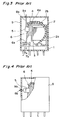
- the test actuator employed in the prior art relay assembly shown in Fig. 3 comprises a push rod 8a having an inner end operatively coupled with the retainer 5 and an outer end slidably extending through an opening 9a defined in a top wall of the casing 9. Therefore, when an external pushing force is applied to the outer end of the push rod8a, the applied push is transmitted to the retainer 5 causing the movable iron bar 4 to pivot counterclockwise as viewed in Fig. 3 about a point 4a of pivot with the movable contact element 6a consequently brought into engagement with the fixed contact element 7b.
- Whether or not the illustrated relay assembly does function properly can be ascertained in any known method, for example, by means of a testing instrument that may be connected electrically with the fixed contact elements 7a and 7b.
- the test actuator comprises a headed push rod 8b having a head formed at the inner end thereof and held in contact with the retainer 5 while the outer end thereof extends axially slidably through an opening 9b that is defined in one of side walls forming the casing 9.
- the relay assembly shown in Fig. 4 functions in a manner substantially similar to that shown in Fig. 3, except for a difference found in direction from which the external pushing force is applied to the push rod.
- the relay unit including the yoke carrying the movable electric contact member and the armature all in assembled state on the base is, after they have been assembled together, encased in the casing 9.
- the employment of the push rod forming a part of the test actuator and being a member separate and independent from the relay unit requires a cumbersome and time-consuming handling in order for it to be repositioned properly within the casing and relative to the relay unit.
- the push rod is pivotally, but non-removably connected to the retainer or any other portion of the relay unit, an alignment of the outer end of the push rod with the opening in the casing as the relay unit is encased relatively into the casing is not easy to accomplish.
- a wall portion of the casing which confronts the movable contact member is formed with a generally U-shaped slit so as to leave a deflectable or pliable tongue which, when deflected by the application of the external pushing force thereto, drives the movable contact member.
- a deflectable or pliable tongue similar to that referred to above is also disclosed in the publication No. 60-186644, but the latter discloses a different structure of the relay unit.
- the relay unit disclosed therein has only a pair of contact members which are connected together when the deflectable or pliable tongue are pushed inwardly of the casing. This is possible because of the use of an actuating lever having its opposite ends confronting the tongue and one of the contact members, respectively, a generally intermediate portion of which is pivotally supported by the free end of the yoke.
- the external push applied to the tongue can be transmitted to one of the contact member through the actuating lever.
- the assignee of the present invention is in possession of the Japanese Laid-open Utility Model Publication No. 56-140127, published October 23, 1981, and also, the Japanese Laid-open Utility Model Publication No. 58-7448 which is a division of the publication No. 56-140127 and was published January 18, 1983.
- a corner region of the casing between the top and one side wall thereof has a corner opening defined therein so as to open upwards and transversely and, hence, so as to have a top open area and a side open area.
- a generally L-shaped covering having top and side wall pieces is normally mounted on the casing to close the corner opening region with the top and side wall pieces closing the top and side open areas, respectively.
- side edges of the side wall confronting the side open area is formed with guide grooves so as to depict a shape similar to the shape of a figure "U" for receiving mating guide edges formed on three sides of the side wall piece of the L-shaped covering.
- an outer surface of the side wall piece is formed with a projection which serves concurrently as a knob and an actuating piece.
- the L-shaped covering referred to above can also be utilized as a test actuator for the relay unit.
- the covering then held in position to close the corner opening in the casing should be removed with an external pull applied to the knob.
- the covering is then re-mounted on the casing with the side edges guided along the mating guide grooves.
- the knob is, as the actuating piece, brought into engagement with the actuating lever and a further external push applied to the covering causes the actuating piece to urge the actuating lever. In this way, the operability of the electromagnetic relay assembly can be tested.
- Japanese publication No. 58-7448 discloses, in addition to what has been disclosed in the Japanese publication No. 56-140127, another embodiment in which mutually confronting side edges of the wall defining the side open area of the corner opening in the casing are formed with outer and inner sets of parallel guide grooves. While the outer set of the guide grooves are identical in structure and function with the guide grooves disclosed in the publication No. 56-140127, the inner set of the parallel guide grooves are utilized when the covering itself is to be used as the test actuator.
- the present invention is a further improvement over the prior art system such as disclosed in any one of the above discussed publications No. 56-140127 and No. 58-7448 and is intended to provide an improved electromagnetic assembly having the test actuator capable of being operated by the application of an external push along one of two directions.
- an electromagnetic relay assembly which comprises a relay unit having a generally elongated contact carrier member supported for pivotal movement about a point of pivot and normally biased in one direction, and a casing enclosing the relay unit and including at least first and second wall members angled relative to each other.
- the casing has a corner opening defined at a corner region between the first and second wall members and delimited by a first open area of a predetermined shape, defined in the first wall member, and a second open area of generally rectangular shape defined in the second wall member.
- the corner opening in the casing is closed by a covering including first and second lids angled relative to each other at an angle equal to the angle delimited between the first and second wall members.
- first and second lids cover the first and second open areas, respectively.
- the second wall member has opposite side edges confronting the side open area, and respective portions of the side edges adjacent the first wall member are formed with guide members for slidably receiving the second lid when the covering is mounted on the casing with said second lid moving in a first direction generally parallel to the second wall member.
- An actuating means is secured to the second lid of the covering for driving the contact carrier member in a direction counter to said one direction when an external pushing force is applied to the second lid to allow said second lid to deform and also for driving the contact carrier member in said direction counter to said one direction when said second lid is further slid in said first direction by an application of an external pushing force to said first lid.
- the casing 9 is shown in the form of a generally cubic body including a generally rectangular top wall 10a and four side walls 10b, 10c, 10d and 10e.
- the corner opening generally identified by 11 is composed of the top and side open areas 11a and 11b of generally rectangular configuration and is defined at a corner region between the top wall 10a and one of the side walls, for example, the side wall 10b. Only respective portions of opposite side edges of the side wall 10b confronting the side open area 11b, that are adjacent the top wall 10a are inwardly recessed at 12 so as to define generally U-sectioned guide grooves in cooperation with one of four side edges of the top wall 10a adjacent the side wall 10b.
- the side wall 10b has an inner surface formed integrally, or otherwise rigidly, with a bench projection 13 transversely protruding inwardly of the casing and positioned a distance below a bottom edge confronting the side open area 11b as best shown in Fig. 2.
- the covering, generally identified by 15, that serves concurrently as a part of the test actuator and is designed according to the present invention is of a generally L-shaped configuration including a top lid 16, adapted to cover the top open area 11a of the corner opening 11 when the covering is mounted on the casing 9, and a side lid 18 extending perpendicular to the top lid 16 and adapted to cover the side open area 11b of the same corner opening 11 when the covering is mounted on the casing 9.
- Respective portions of opposite side edges of the top lid 16 adjacent the side lit 18 are formed with elastically deformable engagement pawls 17 protruding laterally away therefrom for engagement from below with associated opposite side edges of the top wall 10a confronting the top open area 11a, when and so long as the covering 15 is mounted on the casing 9 to close the corner opening 11.
- a rib 19 is formed at a joint between the top and side lids 16 and 18 so as to extend widthwise thereof and also outwardly so that the rib 19 can form a part of a top trim edge that is defined by respective top edges of the side walls 10c to 10e while the top wall 10a is set a distance inwardly as best shown in Fig. 1.
- the bottom projection 20c is integrally formed with a pliable finger 21 extending slantwise downwardly therefrom as viewed in Figs. 1 and 2 and, therefore, when the covering 15 is completely mounted on the casing 9 in the manner described above and so long as no external pushing force is yet applied to the top lid 16, a free end of the pliable finger 21 is brought into engagement with the bench projection 13 as best shown in Fig. 2.
- the corner opening 11 is substantially completely closed by the covering 15 as if the relay assembly embodying the present invention were not the type having the test actuator.
- the covering 15 is retained in position to close the corner opening 11 with the engagement pawls 17 engaged from below with the opposite side edges defining the top open area 11a.
- the covering 15 closing the corner opening 11 in the manner described above can be removed if the covering 15 is forcibly pulled upwards allowing the engagement pawls 17 to deform inwardly or to allow at least the top lid 16 itself to be deformed with the engagement pawls 17 retracted inwardly close towards each other.
- An actuating piece 22 of generally L-shaped configuration having kick-down and push portions 23 and 24 perpendicular to each other is rigidly secured to, or otherwise integrally formed with, an inner surface of the side lid 18 with the kick-down portion 23 positioned immediately beneath the top lid 16. With the actuating piece 22 so secured to the side lid 18, the kick-down portion 23 extends therefrom towards the movable iron bar 4 that carries the movable contact member 6 through the retainer 5 as hereinbefore described in connection with the prior art shown in Figs. 3 and 4, and the push portion 24 confronts the retainer 5, as best shown in Fig. 2.
- the covering 15 according to the present invention is preferably made of elastic material by the reason which will readily be understood from the subsequent description, no matter what type of material is employed for the top and side walls 10a to 10e.
- the actuating piece 22 regardless of whether formed integrally with the covering 15 or whether rigidly secured thereto may have an elasticity, however, the elasticity of the actuating piece 22 should not be of such a value that the actuating piece 22 may be yielded in contact with the retainer 5, by the reason which will also readily be understood from the subsequent description.
- the testing of the electromagnetic relay assembly embodying the present invention can be performed in the following manner.
- the side lid 18 itself is deformed inwardly of the casing 9 to allow the push portion 24 to protrude and, hence, the retainer 5 is pushed in a right-hand direction, as viewed in Fig. 2, causing the movable iron member 4 to pivot about the point 4a of pivot in the manner similar to that occurring when the external push is applied to the top lid 16.
- the covering 15 will not collapse into the casing 9 because the opposite side projections 20a and 20b integral with the side lid 18 are partially retained in and within the guide grooves 12.
- the electromagnetic relay assembly according to the present invention can readily be assembled easier than the prior art relay assembly and that it does not require the covering to be removed and, after having been turned, inserted in readiness for the testing of the relay assembly.
- the opening adapted to be covered by the covering has been described and shown as formed at the corner region between the top and one of the side walls, it may be defined at a corner region between two of the side walls depending on the position of the relay unit within the casing.
- the casing has been shown and described as formed of the generally cubic body, it may be of a generally cylindrical shape comprising a top wall and a cylindrical side wall.
- the movable iron member may be dispensed with to allow the movable contact member to take the place of it.
- the movable contact member should be supported in a manner similar to the illustrated support of the movable iron member by the yoke and, in place of the retainer, an engagement boss may suffice for the engagement with the actuating piece.
- the covering has been described as preferably made of elastic material, rigid and elastic material may be employed for the top and side lids, respectively.
- the top wall may be made of metal and the side lid may be made of an elastic synthetic resin.
- the top lid may have any other shape different from the generally rectangular shape of the side lid and, in such case, the top open area of the corner opening should have a shape similar to the shape of the top lid.
- the elastic finger may be dispensed with.
Landscapes
- Physics & Mathematics (AREA)
- Electromagnetism (AREA)
- Switch Cases, Indication, And Locking (AREA)
- Testing Electric Properties And Detecting Electric Faults (AREA)
- Relay Circuits (AREA)
- Structure Of Telephone Exchanges (AREA)
- Solid State Image Pick-Up Elements (AREA)
- Shielding Devices Or Components To Electric Or Magnetic Fields (AREA)
Applications Claiming Priority (2)
| Application Number | Priority Date | Filing Date | Title |
|---|---|---|---|
| JP35809/91U | 1991-05-21 | ||
| JP1991035809U JP2549515Y2 (ja) | 1991-05-21 | 1991-05-21 | 動作確認用押ボタン付き電磁継電器 |
Publications (3)
| Publication Number | Publication Date |
|---|---|
| EP0514892A2 true EP0514892A2 (de) | 1992-11-25 |
| EP0514892A3 EP0514892A3 (en) | 1995-02-08 |
| EP0514892B1 EP0514892B1 (de) | 1996-08-14 |
Family
ID=12452259
Family Applications (1)
| Application Number | Title | Priority Date | Filing Date |
|---|---|---|---|
| EP92108594A Expired - Lifetime EP0514892B1 (de) | 1991-05-21 | 1992-05-21 | Elektromagnetische Relaisanordnung mit Testschalter |
Country Status (7)
| Country | Link |
|---|---|
| US (1) | US5194839A (de) |
| EP (1) | EP0514892B1 (de) |
| JP (1) | JP2549515Y2 (de) |
| KR (1) | KR920022341A (de) |
| CN (1) | CN1023432C (de) |
| AT (1) | ATE141440T1 (de) |
| DE (1) | DE69212704T2 (de) |
Cited By (2)
| Publication number | Priority date | Publication date | Assignee | Title |
|---|---|---|---|---|
| DE19727990C1 (de) * | 1997-07-01 | 1998-11-19 | Schrack Components Ag | Elektromagnetisches Relais mit Handbetätigungsorgan |
| EP1081732A2 (de) * | 1999-08-31 | 2001-03-07 | Matsushita Electric Works, Ltd. | Electromagnetisches Relais |
Families Citing this family (9)
| Publication number | Priority date | Publication date | Assignee | Title |
|---|---|---|---|---|
| FR2725832B1 (fr) * | 1994-10-17 | 1997-01-03 | Schneider Electric Sa | Appareil contacteur |
| US6522386B1 (en) | 1997-07-24 | 2003-02-18 | Nikon Corporation | Exposure apparatus having projection optical system with aberration correction element |
| JP4168820B2 (ja) * | 2003-04-24 | 2008-10-22 | オムロン株式会社 | 電磁継電器 |
| US7161104B2 (en) | 2003-09-26 | 2007-01-09 | Rockwell Automation Technologies, Inc. | Trip-free PCB mountable relay configuration and method |
| US6949997B2 (en) * | 2003-09-26 | 2005-09-27 | Rockwell Automation Technologies, Inc. | Bi-stable trip-free relay configuration |
| CN1303627C (zh) * | 2004-01-30 | 2007-03-07 | 厦门宏发电声有限公司 | 低高度按钮式小型大功率交直流电磁继电器 |
| JP4998566B2 (ja) * | 2010-01-27 | 2012-08-15 | 富士電機機器制御株式会社 | 電磁接触器と付属ユニットの着脱構造及び付属ユニットに設けた可動フック部の組立方法 |
| CN102607832B (zh) * | 2012-02-29 | 2014-07-02 | 宁波海锐自动化科技有限公司 | 一种继电器配件机械参数测试系统 |
| CN108615659B (zh) * | 2016-12-09 | 2019-12-27 | 浙江正泰电器股份有限公司 | 电磁继电器 |
Citations (2)
| Publication number | Priority date | Publication date | Assignee | Title |
|---|---|---|---|---|
| DE2522297B2 (de) * | 1975-05-20 | 1978-01-05 | Danfoss A/S, Nordborg (Dänemark) | Elektrisches relais |
| US4220937A (en) * | 1978-12-21 | 1980-09-02 | Gulf & Western Manufacturing Company | Electromechanical relay with manual override control |
Family Cites Families (15)
| Publication number | Priority date | Publication date | Assignee | Title |
|---|---|---|---|---|
| DE7929700U1 (de) * | 1979-10-19 | 1980-01-24 | Siemens Ag, 1000 Berlin Und 8000 Muenchen | Elektromagnetisches Relais |
| JPS5942657B2 (ja) * | 1979-11-26 | 1984-10-16 | カネボウ株式会社 | ゴボウジュ−スよりアニオン性高分子電解物質を分離精製する方法 |
| JPS56140127A (en) * | 1980-03-28 | 1981-11-02 | Teijin Ltd | False twisted fused yarn |
| JPS5760633A (en) * | 1980-09-26 | 1982-04-12 | Fujitsu Ltd | Solenoid relay |
| JPS587448A (ja) * | 1981-07-06 | 1983-01-17 | Mitsubishi Petrochem Co Ltd | ポリフエニレンエ−テル樹脂組成物 |
| US4400672A (en) * | 1981-08-27 | 1983-08-23 | Gulf & Western Manufacturing Company | Relay mounting device |
| JPS58191032A (ja) * | 1982-04-30 | 1983-11-08 | Sony Corp | 双方向デ−タ授受システムの端末装置 |
| JPS5875239A (ja) * | 1982-09-22 | 1983-05-06 | Toshiba Corp | 端末装置接続方式 |
| US4542359A (en) * | 1982-11-02 | 1985-09-17 | Nec Corporation | Polar relay |
| JPS6059335A (ja) * | 1983-09-13 | 1985-04-05 | Fuji Xerox Co Ltd | 複写機の倍率変更装置 |
| JPS60186644A (ja) * | 1984-03-05 | 1985-09-24 | Mitsubishi Electric Corp | 自動風呂釜 |
| JPS60263222A (ja) * | 1984-06-11 | 1985-12-26 | Matsushita Electric Ind Co Ltd | キ−ボ−ド装置 |
| JPS62222321A (ja) * | 1986-03-25 | 1987-09-30 | Wacom Co Ltd | 入力装置 |
| JPS6339743A (ja) * | 1986-08-01 | 1988-02-20 | Hitachi Electronics Eng Co Ltd | スピンドル位置決め装置 |
| JP2605786B2 (ja) * | 1988-03-09 | 1997-04-30 | オムロン株式会社 | 電磁継電器 |
-
1991
- 1991-05-21 JP JP1991035809U patent/JP2549515Y2/ja not_active Expired - Fee Related
-
1992
- 1992-05-21 CN CN92104073A patent/CN1023432C/zh not_active Expired - Fee Related
- 1992-05-21 AT AT92108594T patent/ATE141440T1/de not_active IP Right Cessation
- 1992-05-21 EP EP92108594A patent/EP0514892B1/de not_active Expired - Lifetime
- 1992-05-21 US US07/886,244 patent/US5194839A/en not_active Expired - Fee Related
- 1992-05-21 KR KR1019920008773A patent/KR920022341A/ko not_active Application Discontinuation
- 1992-05-21 DE DE69212704T patent/DE69212704T2/de not_active Expired - Fee Related
Patent Citations (2)
| Publication number | Priority date | Publication date | Assignee | Title |
|---|---|---|---|---|
| DE2522297B2 (de) * | 1975-05-20 | 1978-01-05 | Danfoss A/S, Nordborg (Dänemark) | Elektrisches relais |
| US4220937A (en) * | 1978-12-21 | 1980-09-02 | Gulf & Western Manufacturing Company | Electromechanical relay with manual override control |
Cited By (4)
| Publication number | Priority date | Publication date | Assignee | Title |
|---|---|---|---|---|
| DE19727990C1 (de) * | 1997-07-01 | 1998-11-19 | Schrack Components Ag | Elektromagnetisches Relais mit Handbetätigungsorgan |
| US6023212A (en) * | 1997-07-01 | 2000-02-08 | Eh-Schrack Components Ag | Electromagnetic relay with manual actuator |
| EP1081732A2 (de) * | 1999-08-31 | 2001-03-07 | Matsushita Electric Works, Ltd. | Electromagnetisches Relais |
| EP1081732A3 (de) * | 1999-08-31 | 2002-09-18 | Matsushita Electric Works, Ltd. | Electromagnetisches Relais |
Also Published As
| Publication number | Publication date |
|---|---|
| EP0514892B1 (de) | 1996-08-14 |
| ATE141440T1 (de) | 1996-08-15 |
| DE69212704T2 (de) | 1997-02-27 |
| CN1023432C (zh) | 1994-01-05 |
| CN1067135A (zh) | 1992-12-16 |
| DE69212704D1 (de) | 1996-09-19 |
| EP0514892A3 (en) | 1995-02-08 |
| JP2549515Y2 (ja) | 1997-09-30 |
| JPH04129450U (ja) | 1992-11-26 |
| US5194839A (en) | 1993-03-16 |
| KR920022341A (ko) | 1992-12-19 |
Similar Documents
| Publication | Publication Date | Title |
|---|---|---|
| EP0514892B1 (de) | Elektromagnetische Relaisanordnung mit Testschalter | |
| US4811138A (en) | Cassette loading device of video cassette tape recorder | |
| US4553717A (en) | Recording tape cartridge | |
| EP1487001B1 (de) | Elektromagnetisches Relais | |
| US6924719B2 (en) | Electromagnetic relay | |
| US4671697A (en) | Apparatus for mounting electrical appliance on frame | |
| US4758809A (en) | Electromagnetic relay having a multifunction retaining spring | |
| US5103199A (en) | Electromagnetic contactor | |
| EP0051255B1 (de) | Elektromagnetisches Gerät | |
| EP0285110A2 (de) | Druckknopfschalter | |
| US7159814B2 (en) | Magnetic tape cartridge | |
| EP0884743B1 (de) | Verbesserte Struktur eines Drucktastenschalters | |
| US6856220B2 (en) | Electromagnetic relay | |
| EP1365431A2 (de) | Hochfrequenzrelais | |
| US5720385A (en) | Movable contact plate of slide switch | |
| EP1081732B1 (de) | Electromagnetisches Relais | |
| US6781489B2 (en) | High-frequency relay | |
| CN216624110U (zh) | 一种电磁继电器 | |
| US20030057078A1 (en) | System and method for auxiliary contact assembly | |
| JP2748619B2 (ja) | 自動復帰式スライドスイッチ | |
| CA1090469A (en) | Cartridge ejecting mechanism | |
| JPH0754909Y2 (ja) | 電磁継電器 | |
| JPH0945170A (ja) | 操作ボタン装置 | |
| JPH0345409Y2 (de) | ||
| JP2570572Y2 (ja) | 電磁継電器 |
Legal Events
| Date | Code | Title | Description |
|---|---|---|---|
| PUAI | Public reference made under article 153(3) epc to a published international application that has entered the european phase |
Free format text: ORIGINAL CODE: 0009012 |
|
| 17P | Request for examination filed |
Effective date: 19920529 |
|
| AK | Designated contracting states |
Kind code of ref document: A2 Designated state(s): AT BE CH DE DK ES FR GB GR IT LI MC NL PT SE |
|
| PUAL | Search report despatched |
Free format text: ORIGINAL CODE: 0009013 |
|
| RHK1 | Main classification (correction) |
Ipc: H01H 50/02 |
|
| AK | Designated contracting states |
Kind code of ref document: A3 Designated state(s): AT BE CH DE DK ES FR GB GR IT LI MC NL PT SE |
|
| 17Q | First examination report despatched |
Effective date: 19950720 |
|
| GRAH | Despatch of communication of intention to grant a patent |
Free format text: ORIGINAL CODE: EPIDOS IGRA |
|
| GRAA | (expected) grant |
Free format text: ORIGINAL CODE: 0009210 |
|
| AK | Designated contracting states |
Kind code of ref document: B1 Designated state(s): AT BE CH DE DK ES FR GB GR IT LI MC NL PT SE |
|
| PG25 | Lapsed in a contracting state [announced via postgrant information from national office to epo] |
Ref country code: NL Free format text: LAPSE BECAUSE OF FAILURE TO SUBMIT A TRANSLATION OF THE DESCRIPTION OR TO PAY THE FEE WITHIN THE PRESCRIBED TIME-LIMIT Effective date: 19960814 Ref country code: LI Effective date: 19960814 Ref country code: GR Free format text: LAPSE BECAUSE OF FAILURE TO SUBMIT A TRANSLATION OF THE DESCRIPTION OR TO PAY THE FEE WITHIN THE PRESCRIBED TIME-LIMIT Effective date: 19960814 Ref country code: ES Free format text: THE PATENT HAS BEEN ANNULLED BY A DECISION OF A NATIONAL AUTHORITY Effective date: 19960814 Ref country code: DK Effective date: 19960814 Ref country code: CH Effective date: 19960814 Ref country code: BE Effective date: 19960814 Ref country code: AT Effective date: 19960814 |
|
| REF | Corresponds to: |
Ref document number: 141440 Country of ref document: AT Date of ref document: 19960815 Kind code of ref document: T |
|
| REF | Corresponds to: |
Ref document number: 69212704 Country of ref document: DE Date of ref document: 19960919 |
|
| ITF | It: translation for a ep patent filed | ||
| ET | Fr: translation filed | ||
| PG25 | Lapsed in a contracting state [announced via postgrant information from national office to epo] |
Ref country code: SE Effective date: 19961114 Ref country code: PT Effective date: 19961114 |
|
| NLV1 | Nl: lapsed or annulled due to failure to fulfill the requirements of art. 29p and 29m of the patents act | ||
| REG | Reference to a national code |
Ref country code: CH Ref legal event code: PL |
|
| PG25 | Lapsed in a contracting state [announced via postgrant information from national office to epo] |
Ref country code: GB Effective date: 19970521 |
|
| PLBE | No opposition filed within time limit |
Free format text: ORIGINAL CODE: 0009261 |
|
| STAA | Information on the status of an ep patent application or granted ep patent |
Free format text: STATUS: NO OPPOSITION FILED WITHIN TIME LIMIT |
|
| 26N | No opposition filed | ||
| PG25 | Lapsed in a contracting state [announced via postgrant information from national office to epo] |
Ref country code: MC Effective date: 19971130 |
|
| GBPC | Gb: european patent ceased through non-payment of renewal fee |
Effective date: 19970521 |
|
| PG25 | Lapsed in a contracting state [announced via postgrant information from national office to epo] |
Ref country code: FR Free format text: LAPSE BECAUSE OF NON-PAYMENT OF DUE FEES Effective date: 19980130 |
|
| PG25 | Lapsed in a contracting state [announced via postgrant information from national office to epo] |
Ref country code: DE Free format text: LAPSE BECAUSE OF NON-PAYMENT OF DUE FEES Effective date: 19980203 |
|
| REG | Reference to a national code |
Ref country code: FR Ref legal event code: ST |
|
| PG25 | Lapsed in a contracting state [announced via postgrant information from national office to epo] |
Ref country code: IT Free format text: LAPSE BECAUSE OF NON-PAYMENT OF DUE FEES Effective date: 20050521 |