EP0514109A2 - Verfahren und Vorrichtung zur Heizleistungssteuerung - Google Patents
Verfahren und Vorrichtung zur Heizleistungssteuerung Download PDFInfo
- Publication number
- EP0514109A2 EP0514109A2 EP92304232A EP92304232A EP0514109A2 EP 0514109 A2 EP0514109 A2 EP 0514109A2 EP 92304232 A EP92304232 A EP 92304232A EP 92304232 A EP92304232 A EP 92304232A EP 0514109 A2 EP0514109 A2 EP 0514109A2
- Authority
- EP
- European Patent Office
- Prior art keywords
- temperature
- heating
- cooking
- cooking vessel
- control
- Prior art date
- Legal status (The legal status is an assumption and is not a legal conclusion. Google has not performed a legal analysis and makes no representation as to the accuracy of the status listed.)
- Granted
Links
Images


Classifications
-
- F—MECHANICAL ENGINEERING; LIGHTING; HEATING; WEAPONS; BLASTING
- F24—HEATING; RANGES; VENTILATING
- F24C—DOMESTIC STOVES OR RANGES ; DETAILS OF DOMESTIC STOVES OR RANGES, OF GENERAL APPLICATION
- F24C3/00—Stoves or ranges for gaseous fuels
- F24C3/12—Arrangement or mounting of control or safety devices
- F24C3/126—Arrangement or mounting of control or safety devices on ranges
-
- G—PHYSICS
- G05—CONTROLLING; REGULATING
- G05D—SYSTEMS FOR CONTROLLING OR REGULATING NON-ELECTRIC VARIABLES
- G05D23/00—Control of temperature
- G05D23/19—Control of temperature characterised by the use of electric means
- G05D23/1951—Control of temperature characterised by the use of electric means with control of the working time of a temperature controlling device
Definitions
- the present invention relates to a cooking temperature control method and a cooking apparatus utilizing a cooking temperature control.
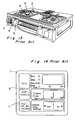
- a commercially available gas range is shown in Figs. 13 and 14.
- Fig. 13 illustrates a perspective view of the conventional gas range
- Fig. 14 illustrates, on an enlarged scale, a control panel 1 employed in the conventional gas range shown in Fig. 13 and installed at a front thereof accessible to a user.
- the conventional gas range comprises, in addition to the control panel 1 referred to above, at least one gas burner 2, a heat adjusting knob 4, a temperature sensor 5 for detecting a temperature at a bottom of a cooking vessel, for example, a frying pan, and a fire extinguishing button 6.
- the control panel 1 includes, as shown in Fig.
- a "TEMPURA” key 7 that, when operated, sets the gas range in a frying mode in which the temperature of cooking oil is automatically controlled to a target temperature required for a particular cooking; and a “SIMMERING” key 8 that, when operated, sets the gas range in a simmering mode in which an automatic fire extinguishing timer adapted to be activated upon boiling and, at the same time, the heating power is set to a gentle heating.
- a temperature adjusting scheme (hereinafter referred to as a frying mode) employed therein works with a standard pan, unique to a particular make of gas ranges, in such a manner as to accomplish a temperature control by adequately adjusting the difference between the temperature of cooking oil, contained in the pan in a predetermined quantity, and the temperature of a pan sensor that measures the temperature in contact with the bottom of the pan. Accordingly, so far as the standard pan is employed which meets requirements set up by a manufacturer of the standard pans, the cooking oil in the standard pan can be heated to a value substantially matching with the preset temperature.
- the present invention has for its essential object to provide a frying cooker utilized for preparing fried food such as, for example, tempura, wherein design has been made to automatically adjust the temperature of cooking oil to a target temperature required for a particular cooking regardless of the wall thickness of and/or the type of material for the pan used.
- Another important object of the present invention is to substantially eliminate inconveniences which would, in the case where the temperature of the cooking oil is detected indirectly by a sensor for detecting the temperature at the bottom of a cooking vessel, for example, a frying pan, occur as a result of a substantial difference between the actual temperature of the cooking oil being heated and the temperature at the bottom of the pan which may vary depending on the type of material for the pan and/or the thickness of at least a bottom of the pan.
- the present invention provides a method of controlling a heating of food material to be fried in a cooking oil contained in a cooking vessel with the use of a heating apparatus comprising a heating means for heating the food material accommodated in the cooking vessel, a temperature detecting means for detecting a temperature of the cooking vessel and a heating control means operable in response to a signal fed from the temperature detecting means to control a heating power generated by the heating means.
- the heating control method comprises the steps of detecting a temperature increase characteristic of the cooking vessel by means of the temperature detecting means subsequent to a start of heating and also determining, in a first temperature region of the temperature increase characteristic, a characteristic of the cooking vessel such as type of material for and a wall thickness of the cooking vessel; determining the quantity of the cooking oil in the cooking vessel in a second temperature region of the temperature increase characteristic which is higher than said first temperature region; and controlling the heating power of the heating means according to both a result of determination of the characteristic of the cooking vessel and a result of determination of the quantity of the cooking oil.
- the present invention according to another aspect thereof provides a cooking apparatus which comprises a heating means for heating a cooking vessel containing material to be heated; a temperature detecting means for detecting a temperature of the cooking vessel; a heating control means operable in response to a signal from the temperature detecting means for controlling a heating power generated by the heating means.
- the temperature detecting means detects a temperature increase characteristic of the cooking vessel as time passes subsequent to a start of heating.
- the heating control means is operable to determine, in a first temperature region of the temperature increase characteristic, a characteristic of the cooking vessel such as type of material for and a wall thickness of the cooking vessel, to determine the quantity of the cooking oil in the cooking vessel in a second temperature region of the temperature increase characteristic which is higher than said first temperature region, and to control the heating power of the heating means according to both a result of determination of the characteristic of the cooking vessel and a result of determination of the quantity of the cooking oil.
- Fig. 1 illustrates, in a perspective view, a gas range embodying the present invention
- Fig. 2 is a block diagram showing a gas control system, forming a heating means, and an electronic circuit including a microcomputer
- Figs. 3 to 6 are flowcharts showing respective sequences of operation performed mainly by the microcomputer.
- the gas range embodying the present invention is provided with a warning lamp 9.
- Fig. 2 illustrates the structure in a block of one of a plurality of, for example, two, gas burners forming parts of a heating means 10.
- the heating means 10 is broadly constituted by an electronic circuit block 11.
- the heating means 10 includes a gas supply pipe 12; an ON/OFF button 6; a heating power adjustment lever 4; a main valve 13 operatively coupled with the ON/OFF button 6 for selectively opening and closing the gas supply pipe 12; an electronically controlled safety valve 14 for selectively opening and closing the gas supply pipe 12; a lead wire 14a extending from the safety valve 14; a heating power adjustment mechanism 15 for manually adjusting a heating power by a manipulation of the heating power adjusting lever 4; an electronically controlled electromagnetic valve 16 for setting a minimum gas flow; a lead wire 16a leading from the electromagnetic valve 16; a bypass nozzle 17 for setting the minimum gas flow during a closure of the electromagnetic valve 16; a main nozzle 18 for setting a maximum gas flow; a switch 18 operatively associated with the ON/OFF button 6; a lead wire 19a leading from the switch 19; a gas burner 2; a vessel temperature sensor 5; an ignition electrode 20; and a lead wire 20a leading from the ignition electrode 20.
- An electronic circuit block 11 includes a 100-volt AC power supply line 21 connected to a power circuit 23 for the supply of an electric power thereto and also includes a menu select key 22, an igniter 31, a warning buzzer 32 and the warning lamp 9.
- the burner switch 19 operatively associated with the ON/OFF button 6 is turned on to supply the electric power to the safety valve and the electromagnetic valve 16, which are controlled by a heating control means 24, to open the safety valve 14 and the electromagnetic valve 16.
- Gas in the heating means 24 is then supplied to the heating power adjustment mechanism 15 through the gas supply pipe 12 by way of the main valve 13 and the safety valve 14, then to the main nozzle 18 in part through the electromagnetic valve 16 and in part through the bypass nozzle 17 and finally to the burner 2.
- the gas emerging from the burner 2 is ignited by sparks generated from the ignition electrode 20 to which a high voltage is applied from the igniter 30 which operates for a limited time subsequent to the burner switch 19 having been turned on. Combustion of the gas so ignited in the manner described above takes place.
- both of the safety valve 14 and the electromagnetic valve 16 are held in an open position, and the heat value or heating power can be adjusted by the user by manipulating the heating power adjusting lever 4 to control the heating power adjustment mechanism 15. It is to be noted that the heating power adjustment mechanism 15 is held in a position to attain the minimum available heating power, the electromagnetic valve 16 is in a closed position while the minimum gas flow through the bypass nozzle 17 is utilized to accomplish the combustion at the minimum available heating power.
- a setting of the heating power adjusting lever 4 to a minimum power position may serve an alternative to the electromagnetic valve 14.
- the burning gas can be extinguished either when the ON/OFF button 6 is subsequently manipulated or when the supply of the electric power to the safety valve 14 is interrupted.
- a continued combustion of the gas results in an increase of the temperature of the food material to be cooked, accompanied by a corresponding change in resistance of the vessel temperature sensor 5 which employs a thermistor as a temperature measuring element.
- the change in resistance of the vessel temperature sensor 5 is inputted to the electronic circuit block 11 through the lead wire 5a.
- a temperature detecting means 25 operable to add or subtract a predetermined coefficient to or from the resistance value of the vessel temperature sensor 5, which varies with change in temperature, and then to convert it into a temperature.
- Fig. 3 illustrates a basic structure of various determining means operating during the tempura (frying) mode that is initiated when the TEMPURA key shown in Fig. 14 has been pressed.
- the extent to which a pan containing food material is heated by the heat generated by a heating means controlled by the heating control means 24 is detected by the temperature detecting means 25.
- Both of the shape of the pan and the type of material for the pan are determined by a material determining means 25.
- a high temperature start temperature correcting means 33 is provided, and a preset change time temperature correcting means 34 is also provided, as a countermeasure to meet with a situation in which a preset temperature is changed during the use, to accomplish a temperature correction at the time of change of the preset temperature during the use.
- an overheating prevention determining means 29 is operated, in the event that the temperature detected by the temperature detecting means 25 during the low fire heating attains an overheating suppression temperature ⁇ , so that, when an overheating prevention temperature is attained, a control signal can be supplied from the overheating prevention determining means 29 to both of the heating control means 24 and a warning means 32.
- Block A shown therein illustrates contents of the material determining means 26 and the L temperature correction value determining means 30.
- a preset temperature appropriate to a particular cooking purpose has been keyed in by manipulating keys 7a and 7b (shown in Fig. 14)
- a standard pan control temperature Z2 relative to the preset temperature is determined at block 38.
- the material determining means 26 is operated only when an initial value of the detected temperature (i.e., the temperature detected by the temperature detecting means 25) is lower than 50°C, and the detected temperature is inputted to the material determining means 28 at intervals of a predetermined time so that, when the detected temperature attains 50°C and 60°C, material variables X1 and X2 are sequentially calculated by dividing the difference between the temperatures detected a predetermined time after the detected temperatures have exceeded 50°C and 60°C and the temperatures detected at the time the detected temperatures have attained 50°C and 60°C, by the predetermined time.
- the both are multiplied together to provide a material determined value X3 which is subsequently compared with a determining value ⁇ .
- the L temperature correction value determining means 30 performs a rank classification at successive blocks 36 according to the magnitude of the material determined value X3 determined at block 39 and determines a L correction value Z4 at block 36 for each rank, which is subsequently stored in a correction value storage 37 as an L correction value Z4m while outputting a signal to the heating control means 24.
- Block B shown in Fig. 4 illustrates contents of the high temperature start correction means 33.
- the standard pan control temperature Z2 relative to the preset temperature is determined at block 38.
- the material determining means 26 is operated only when an initial value of the detected temperature (i.e., the temperature detected by the temperature detecting means 25) is higher than 50°C.
- the temperature difference DF between the standard pan control temperature Z2 and the initial value of the detected temperature is determined at block 49, the magnitude of said temperature difference DF being classified into ranks so that the H correction value Z3 appropriate to a particular rank can be determined at one of blocks 50.
- the L correction value Z4m stored during the previous cycle of use is used as an L correction value Z4.
- Fig. 12 illustrates contents of the quantity determining means 27 and the H temperature correction value determining means 28.
- the quantity determining means 27 reads the detected temperature of the temperature detecting means into the material determining means 26 at intervals of a predetermined time; when the detected temperature attains 100°C, calculates a quantity determining variable X4 at block 40 by dividing the difference between the temperature detected a predetermined time after the detected temperature has exceeded 100°C and the temperature detected at the time the detected temperature has attained 100°C, by the predetermined time; determine the H correction value Z3 at block 42 in reference to an interrelationship between variables W1 to S5 determined at block 40 for each of ranks of the material determined value X3 determined at block 39 and the quantity determining variable X4 determined at block 40; and substitutes a predetermined value ⁇ for the L correction value Z4; stores in a correction value storage 37 as a stored H correction
- Fig. 6 illustrates the overheating control means 29.
- a decision is made to determine if the detected temperature is higher than the overheating suppression temperature ⁇ and, if it is higher than the overheating suppression temperature ⁇ , an overheating suppression signal is outputted at block P2 to a next step and, at the same time, a heating power reducing command is generated to the warning buzzer 32 and the heating control means 24 at block P3.
- a signal indicative of the detected temperature being higher than the overheating prevention temperature ⁇ is outputted at block P8 to energize the warning buzzer 32 and, at the same time, to command the heating control means 24 to interrupt the heating.
- Fig. 7 illustrates contents of the heating control means 24.
- block 44 at which the control temperature Z1 is set to be unable to exceed the overheating prevention temperature ⁇ , while allowing the heating means 10 to heat until the detected temperature attains a value equal to the control temperature Z1.
- a temperature control unit 47 monitors both of the control temperature Z1 and the status of the detected temperature and outputs to the heating unit 10 one of a low heating command when the control temperature Z1 is lower than the detected temperature and a high heating command when the control temperature Z1 is higher than the detected temperature.
- Fig. 8 illustrates the preset change time temperature correcting means 34.
- a decision is made to determine if a new preset temperature is lower than the current preset temperature and, if the new preset temperature is high than the current preset time, a new H correction value Z3 is determined at block P10 in reference to a relationship between the stored H corrected temperature, the current H corrected temperature and the difference between the respective temperatures before and after the change of the preset temperature so that a new control temperature Z1 can subsequently be determined at block P11.
- the present invention makes it possible to make the temperature of the cooking oil attain a value substantially equal to the preset temperature regardless of the thickness of the material for the pan, even at the high temperature start at which time the type of material for the pan cannot be determined, and/or even when the preset temperature is changed during the course of heating.
- the pan 52 accommodating food material to be cooked by the heating means 10 is, as shown in Fig. 9, heated by flames emanating from the burner 2 touching heating points 53 at the bottom of the pan 52, with heat consequently transmitted to the whole of the pan 52. Simultaneously with the conduction of heat to the pan 52,. the heat is transmitted to the food material within the pan 52 with convection taking place within the pan 52. As a result of the convection taking place within the pan 52, the pan 52 with the food material therein can be uniformly heated, accompanied by an increase in temperature of the vessel temperature sensor 5.
- the vessel temperature sensor 5 for the measurement of the temperature at the bottom of the pan 52 which is disposed at a position aligned with the center of the bottom of the pan 52, essentially detects the previously described two conditions of heat. (However, it is pointed out that, in order to lessen the thermal influence which may be brought on the vessel temperature sensor 5, the vessel temperature sensor 5 is cooled by a secondary air for cooling as indicated by 54.) In this condition, where the pan 52 is made of material having a high thermal conductivity such as aluminum, the temperature of the vessel temperature sensor 5 due to a thermal conduction at the bottom of the pan 52 regardless of the temperature of the cooking oil within the pan 52.
- the temperature of the vessel temperature sensor 5 increases with increase of the temperature of the cooking oil. Also, since the convection does not occur vigorously in the cooking oil unless the temperature of the cooking oil attains a value higher than 100°C, the foregoing tendency occurs considerably before the vigorous convection takes place within the pan 52.
- the above described tendency as actually measured is shown. As shown therein, subsequent to the start of heating, the rate of increase of the temperature is highest in the case of an thin-walled aluminum pan shown by A and lowest in the case of the thick-walled iron pan shown by C with the thick-walled aluminum pan exhibiting a value generally intermediate therebetween as shown by B.
- Fig. 11 illustrates how the increase in temperature of the vessel temperature sensor 5 increases with a change in quantity of the cooking oil within an aluminum pan having a wall thickness of 4mm. Fig. 11 makes it clear that, since the convection takes place vigorously within the pan when the cooking oil is heated to a temperature exceeding 100°C, the rate of increase of the sensor temperature varies with a change in quantity of the cooking oil.
- Whether the thermal conductivity is high or whether the thermal conductivity is low may vary even then the sensor temperature exhibits a high temperature.
- a temperature curve T2 exhibited by the vessel temperature sensor 5 measuring the bottom temperature of an iron pan with the cooking oil heated to 180°C and a temperature curve T3 exhibited by the vessel temperature sensor 5 when the cooking oil within the same iron pan is heated to 180°C.
- the material determining means 26 determines, as discussed with reference to Fig. 10, the material determined value X3 in reference to the "rate of increase of the temperature at the bottom of the pan when each type of pan is at a low temperature of each pan", the smaller the material determined value X3 is, the lower the thermal conductivity the material (ferrous type) has. For a given ferrous material, the thermal conductivity becomes high with increase in wall thickness and, therefore, any correction is needed. For this purpose, depending on the value of the material determined value X3, the correction is carried out to calculate the L corrected value Z4.
- the difference between the preset temperature, which may vary depending on the type of pan, and the temperature of the cooking oil is automatically eliminated.
- the purpose of storage of the L correction value Z4 as the stored L correction value Z4m is that, in view of the fact that in most households a particular pan once used for frying purpose or designed for use in frying is generally limited for use in frying, the previous condition of use in which the pan was used for frying is stored in the storage unit 37 and, at the time of high temperature start, the condition of the pan is also stored because the type of material for the pan cannot be determined at a high temperature of the cooking oil, so that the high temperature start temperature correcting means 33 shown in Block B in Fig. 4 can be used.
- the control temperature Z1 has to be composed of the correction value (the H correction value Z3m) for equalizing the oil temperature by progressively subtracting the correction value from the initially corrected value, and the correction value (the L correction value Z3) superimposed on the preset temperature and having no change with time.
- the H correction value Z3 is corrected in reference to the correlation between the quantity determining variable X4, determined by the quantity determining means 40, and the material determined value, and, after the predetermined value ⁇ has been substituted for the L correction value Z4, various correction values are stored in the storage unit 37 in a manner similar to the foregoing.
- the overheating preventing means 29 has been described with reference to Fig. 6, this overheating preventing means is effective to avoid an occurrence of oil fire which would occur when the condition in which the pan used is very small while the minimum heat calorie of the heating unit 10 is very high (for example, the condition in which a small quantity of cooking oil is applied to a frying pan) is allowed to stand for a substantial length of time. Therefore, the use of the overheating suppression temperature ⁇ is effective to permit the user to be informed of the excessively high temperature and then to reduce the heating power before an automatic fire extinguishment takes place, thereby eliminating the problem associated with an unnecessary extinguishment and a difficulty to use.
- the control temperature Z1 is varied to suit to the nature of the pay so that the oil temperature, that is, the temperature of the cooking oil, can attain a value substantially equal to the preset temperature.
- the H correction value Z3 is effective to avoid the possibility that the preset temperature and the oil temperature do not coincide with each other due to the relationship with the difference between the new prepet temperature and the previous preset temperature and the detected temperature.
- the cooking apparatus according to the present invention can being about the following advantages:
Applications Claiming Priority (2)
| Application Number | Priority Date | Filing Date | Title |
|---|---|---|---|
| JP3113215A JP3063224B2 (ja) | 1991-05-17 | 1991-05-17 | 調理器 |
| JP113215/91 | 1991-05-17 |
Publications (3)
| Publication Number | Publication Date |
|---|---|
| EP0514109A2 true EP0514109A2 (de) | 1992-11-19 |
| EP0514109A3 EP0514109A3 (de) | 1994-02-16 |
| EP0514109B1 EP0514109B1 (de) | 1998-02-11 |
Family
ID=14606489
Family Applications (1)
| Application Number | Title | Priority Date | Filing Date |
|---|---|---|---|
| EP92304232A Expired - Lifetime EP0514109B1 (de) | 1991-05-17 | 1992-05-12 | Verfahren und Vorrichtung zur Heizleistungssteuerung |
Country Status (6)
| Country | Link |
|---|---|
| US (1) | US5240725A (de) |
| EP (1) | EP0514109B1 (de) |
| JP (1) | JP3063224B2 (de) |
| KR (1) | KR950005886B1 (de) |
| AU (1) | AU635173B2 (de) |
| DE (1) | DE69224404T2 (de) |
Cited By (1)
| Publication number | Priority date | Publication date | Assignee | Title |
|---|---|---|---|---|
| EP0788292A1 (de) * | 1996-02-02 | 1997-08-06 | AEG Hausgeräte GmbH | Kochmulde mit automatischer Regelung des Garvorganges |
Families Citing this family (25)
| Publication number | Priority date | Publication date | Assignee | Title |
|---|---|---|---|---|
| US5398597A (en) * | 1993-09-24 | 1995-03-21 | Henny Penny Corporation | Electronic control system for cooking system |
| CA2144201C (en) * | 1994-03-17 | 1999-05-25 | Charles A. Maher, Jr. | Electronic control system for a heating apparatus |
| US6018150A (en) * | 1995-03-23 | 2000-01-25 | Tridelta Industries, Inc. | Method of heating a medium to a desired temperature |
| US5582755A (en) * | 1995-04-04 | 1996-12-10 | Tridelta Industries, Inc. | Apparatus and method for classifying a medium in a cooking chamber |
| US5617777A (en) * | 1995-06-01 | 1997-04-08 | The Frymaster Corporation | Deep fat frying apparatus with automated oil management |
| US5809994A (en) * | 1996-09-11 | 1998-09-22 | Tridelta Industries, Inc. | Electronic control system for a heating apparatus |
| US5827556A (en) * | 1996-10-23 | 1998-10-27 | Tridelta Industries, Inc. | Electronic controller for heating apparatus |
| JP3717727B2 (ja) * | 1999-10-14 | 2005-11-16 | リンナイ株式会社 | 焼物調理器 |
| US20040016348A1 (en) * | 2002-07-24 | 2004-01-29 | Richard Sharpe | Electronic cooking pan systems and methods |
| JP2002280157A (ja) * | 2001-03-19 | 2002-09-27 | Matsushita Electric Ind Co Ltd | 誘導加熱調理器 |
| JP2004081430A (ja) * | 2002-08-26 | 2004-03-18 | Paloma Ind Ltd | フライヤー |
| US8337757B2 (en) * | 2008-02-07 | 2012-12-25 | Precision Combustion, Inc. | Reactor control method |
| US10252852B2 (en) | 2011-04-22 | 2019-04-09 | Jbt Food & Dairy Systems B.V. | Adaptive packaging for food processing systems |
| US9241510B2 (en) * | 2011-04-23 | 2016-01-26 | Ics Solutions B.V. | Apparatus and method for optimizing and controlling food processing system performance |
| US8893518B2 (en) | 2011-04-25 | 2014-11-25 | Ics Solutions B.V. | Accelerating, optimizing and controlling product cooling in food processing systems |
| US9955711B2 (en) | 2011-05-20 | 2018-05-01 | Jbt Food & Dairy Systems B.V. | Method and apparatus for increased product throughput capacity, improved quality and enhanced treatment and product packaging flexibility in a continuous sterilizing system |
| US9131729B2 (en) | 2011-09-28 | 2015-09-15 | Ics Solutions B.V. | Safe and efficient thermal transfer media for processing of food and drink products |
| US9357881B2 (en) | 2012-03-31 | 2016-06-07 | Pitco Frialator, Inc. | Oil level detection system for deep fat fryer |
| KR101413982B1 (ko) * | 2012-11-29 | 2014-07-04 | 린나이코리아 주식회사 | 가스레인지의 조리용기별 과열방지 자동 온도보정방법 |
| JP6489935B2 (ja) * | 2015-05-22 | 2019-03-27 | 株式会社ハーマン | ガスコンロ |
| US10588443B2 (en) * | 2016-03-04 | 2020-03-17 | CE Brands, LLC | Smart slow cooker |
| CN108784322B (zh) * | 2017-05-04 | 2020-11-27 | 佛山市顺德区美的电热电器制造有限公司 | 一种控制方法和设备 |
| CA3100563A1 (en) * | 2018-05-18 | 2019-11-21 | Pioneering Technology Corp. | Temperature modulation in a cooking apparatus |
| US11497341B2 (en) * | 2019-10-03 | 2022-11-15 | Bsh Home Appliances Corporation | Temperature sensing and smart gas cooking |
| CN110957035A (zh) * | 2019-10-17 | 2020-04-03 | 佛山市云米电器科技有限公司 | 一种能评估身体健康状态的方法及家庭智能系统 |
Citations (7)
| Publication number | Priority date | Publication date | Assignee | Title |
|---|---|---|---|---|
| EP0146705A1 (de) * | 1983-10-26 | 1985-07-03 | Kurt Wolf & Co. KG | Anordnung zum Ableiten eines vom Temperaturanstieg einer Temperatur-Zeit-Kennlinie abhängigen Steuersignals in einem Heizsystem |
| EP0309770A2 (de) * | 1987-09-30 | 1989-04-05 | FOOD AUTOMATION-SERVICE TECHNIQUES, INC. a corporation of the State of Delaware | Vorrichtung zur Überwachung der Temperatur in einem Kochgerät |
| EP0348298A1 (de) * | 1988-06-22 | 1989-12-27 | Seb S.A. | Verfahren und Vorrichtung zur thermischen Regulierung eines Heizgerätes und mit dieser Vorrichtung versehenes Heizgerät |
| FR2633482A1 (fr) * | 1988-06-22 | 1989-12-29 | Seb Sa | Recipient culinaire, procede et dispositif de regulation thermique du chauffage de ce recipient |
| US4994652A (en) * | 1988-04-09 | 1991-02-19 | Fissler Gmbh | Device for controlling the heating output of the heating element of a cooking or heating plate |
| EP0441364A1 (de) * | 1990-02-09 | 1991-08-14 | Matsushita Electric Industrial Co., Ltd. | Verfahren zur thermischen Regulierung eines Kochgefässes und Vorrichtung zur Durchführung dieses Verfahrens |
| EP0514212A1 (de) * | 1991-05-17 | 1992-11-19 | Matsushita Electric Industrial Co., Ltd. | Heizeinrichtung und Verfahren zur Leistungssteuerung |
Family Cites Families (3)
| Publication number | Priority date | Publication date | Assignee | Title |
|---|---|---|---|---|
| US3423210A (en) * | 1962-06-04 | 1969-01-21 | Mcdonalds System Inc | Method for signalling the completion of cooking of a food product in a cooking bath |
| DE3323399C2 (de) * | 1983-06-29 | 1985-04-25 | Kurt Wolf & Co Kg, 7547 Wildbad | Vorrichtung zum Steuern des Gar- bzw. Kochvorganges bei einem Dampfdruckkochgefäß |
| US5090305A (en) * | 1990-10-10 | 1992-02-25 | Daylight Donut Flour & Equipment Co. | Deep fat fryer |
-
1991
- 1991-05-17 JP JP3113215A patent/JP3063224B2/ja not_active Expired - Fee Related
-
1992
- 1992-05-12 AU AU16172/92A patent/AU635173B2/en not_active Ceased
- 1992-05-12 US US07/881,635 patent/US5240725A/en not_active Expired - Lifetime
- 1992-05-12 DE DE69224404T patent/DE69224404T2/de not_active Expired - Fee Related
- 1992-05-12 EP EP92304232A patent/EP0514109B1/de not_active Expired - Lifetime
- 1992-05-16 KR KR1019920008299A patent/KR950005886B1/ko not_active IP Right Cessation
Patent Citations (7)
| Publication number | Priority date | Publication date | Assignee | Title |
|---|---|---|---|---|
| EP0146705A1 (de) * | 1983-10-26 | 1985-07-03 | Kurt Wolf & Co. KG | Anordnung zum Ableiten eines vom Temperaturanstieg einer Temperatur-Zeit-Kennlinie abhängigen Steuersignals in einem Heizsystem |
| EP0309770A2 (de) * | 1987-09-30 | 1989-04-05 | FOOD AUTOMATION-SERVICE TECHNIQUES, INC. a corporation of the State of Delaware | Vorrichtung zur Überwachung der Temperatur in einem Kochgerät |
| US4994652A (en) * | 1988-04-09 | 1991-02-19 | Fissler Gmbh | Device for controlling the heating output of the heating element of a cooking or heating plate |
| EP0348298A1 (de) * | 1988-06-22 | 1989-12-27 | Seb S.A. | Verfahren und Vorrichtung zur thermischen Regulierung eines Heizgerätes und mit dieser Vorrichtung versehenes Heizgerät |
| FR2633482A1 (fr) * | 1988-06-22 | 1989-12-29 | Seb Sa | Recipient culinaire, procede et dispositif de regulation thermique du chauffage de ce recipient |
| EP0441364A1 (de) * | 1990-02-09 | 1991-08-14 | Matsushita Electric Industrial Co., Ltd. | Verfahren zur thermischen Regulierung eines Kochgefässes und Vorrichtung zur Durchführung dieses Verfahrens |
| EP0514212A1 (de) * | 1991-05-17 | 1992-11-19 | Matsushita Electric Industrial Co., Ltd. | Heizeinrichtung und Verfahren zur Leistungssteuerung |
Cited By (1)
| Publication number | Priority date | Publication date | Assignee | Title |
|---|---|---|---|---|
| EP0788292A1 (de) * | 1996-02-02 | 1997-08-06 | AEG Hausgeräte GmbH | Kochmulde mit automatischer Regelung des Garvorganges |
Also Published As
| Publication number | Publication date |
|---|---|
| KR950005886B1 (ko) | 1995-06-02 |
| EP0514109A3 (de) | 1994-02-16 |
| EP0514109B1 (de) | 1998-02-11 |
| JPH04356619A (ja) | 1992-12-10 |
| KR920021100A (ko) | 1992-12-18 |
| US5240725A (en) | 1993-08-31 |
| AU635173B2 (en) | 1993-03-11 |
| JP3063224B2 (ja) | 2000-07-12 |
| DE69224404D1 (de) | 1998-03-19 |
| DE69224404T2 (de) | 1998-06-04 |
| AU1617292A (en) | 1992-11-19 |
Similar Documents
| Publication | Publication Date | Title |
|---|---|---|
| EP0514109B1 (de) | Verfahren und Vorrichtung zur Heizleistungssteuerung | |
| AU647269B2 (en) | Heating apparatus and heating power control method | |
| EP0089247B1 (de) | Kochtemperaturregelungssystem | |
| JP6722542B2 (ja) | 加熱調理器 | |
| KR940008514B1 (ko) | 곤로의 제어장치 | |
| JP2979654B2 (ja) | 調理器 | |
| JP2970655B2 (ja) | 調理器 | |
| JP3024632B2 (ja) | 調理器 | |
| JP3055531B2 (ja) | 調理器 | |
| JP2637035B2 (ja) | 調理装置 | |
| JP2664565B2 (ja) | 加熱調理器 | |
| JP2664015B2 (ja) | 調理装置 | |
| JPH0777330A (ja) | 加熱調理器 | |
| JP2637888B2 (ja) | 加熱調理器 | |
| JPH05280740A (ja) | 調理装置 | |
| JP3021804B2 (ja) | 調理器用自動消火装置 | |
| KR940008517B1 (ko) | 곤로의 제어장치 | |
| JP2722428B2 (ja) | 調理装置 | |
| JP2553443B2 (ja) | 加熱調理器 | |
| JPH08105629A (ja) | 調理装置 | |
| KR940008516B1 (ko) | 곤로의 제어장치 | |
| KR950004617B1 (ko) | 곤로의 제어장치 | |
| JPH086928B2 (ja) | 自動調理器 | |
| JPH03204514A (ja) | 加熱調理制御方法 | |
| JPH0560326A (ja) | 調理用温度制御装置 |
Legal Events
| Date | Code | Title | Description |
|---|---|---|---|
| PUAI | Public reference made under article 153(3) epc to a published international application that has entered the european phase |
Free format text: ORIGINAL CODE: 0009012 |
|
| 17P | Request for examination filed |
Effective date: 19920529 |
|
| AK | Designated contracting states |
Kind code of ref document: A2 Designated state(s): DE FR GB IT SE |
|
| PUAL | Search report despatched |
Free format text: ORIGINAL CODE: 0009013 |
|
| AK | Designated contracting states |
Kind code of ref document: A3 Designated state(s): DE FR GB IT SE |
|
| 17Q | First examination report despatched |
Effective date: 19950703 |
|
| GRAG | Despatch of communication of intention to grant |
Free format text: ORIGINAL CODE: EPIDOS AGRA |
|
| GRAH | Despatch of communication of intention to grant a patent |
Free format text: ORIGINAL CODE: EPIDOS IGRA |
|
| GRAH | Despatch of communication of intention to grant a patent |
Free format text: ORIGINAL CODE: EPIDOS IGRA |
|
| GRAA | (expected) grant |
Free format text: ORIGINAL CODE: 0009210 |
|
| AK | Designated contracting states |
Kind code of ref document: B1 Designated state(s): DE FR GB IT SE |
|
| ITF | It: translation for a ep patent filed |
Owner name: JACOBACCI & PERANI S.P.A. |
|
| REF | Corresponds to: |
Ref document number: 69224404 Country of ref document: DE Date of ref document: 19980319 |
|
| ET | Fr: translation filed | ||
| PLBE | No opposition filed within time limit |
Free format text: ORIGINAL CODE: 0009261 |
|
| STAA | Information on the status of an ep patent application or granted ep patent |
Free format text: STATUS: NO OPPOSITION FILED WITHIN TIME LIMIT |
|
| 26N | No opposition filed | ||
| REG | Reference to a national code |
Ref country code: GB Ref legal event code: IF02 |
|
| PGFP | Annual fee paid to national office [announced via postgrant information from national office to epo] |
Ref country code: SE Payment date: 20070508 Year of fee payment: 16 |
|
| PGFP | Annual fee paid to national office [announced via postgrant information from national office to epo] |
Ref country code: DE Payment date: 20070510 Year of fee payment: 16 |
|
| PGFP | Annual fee paid to national office [announced via postgrant information from national office to epo] |
Ref country code: GB Payment date: 20070509 Year of fee payment: 16 |
|
| PGFP | Annual fee paid to national office [announced via postgrant information from national office to epo] |
Ref country code: IT Payment date: 20070528 Year of fee payment: 16 |
|
| PGFP | Annual fee paid to national office [announced via postgrant information from national office to epo] |
Ref country code: FR Payment date: 20070510 Year of fee payment: 16 |
|
| GBPC | Gb: european patent ceased through non-payment of renewal fee |
Effective date: 20080512 |
|
| REG | Reference to a national code |
Ref country code: FR Ref legal event code: ST Effective date: 20090119 |
|
| PG25 | Lapsed in a contracting state [announced via postgrant information from national office to epo] |
Ref country code: DE Free format text: LAPSE BECAUSE OF NON-PAYMENT OF DUE FEES Effective date: 20081202 Ref country code: FR Free format text: LAPSE BECAUSE OF NON-PAYMENT OF DUE FEES Effective date: 20080602 |
|
| PG25 | Lapsed in a contracting state [announced via postgrant information from national office to epo] |
Ref country code: GB Free format text: LAPSE BECAUSE OF NON-PAYMENT OF DUE FEES Effective date: 20080512 |
|
| PG25 | Lapsed in a contracting state [announced via postgrant information from national office to epo] |
Ref country code: IT Free format text: LAPSE BECAUSE OF NON-PAYMENT OF DUE FEES Effective date: 20080512 |
|
| PG25 | Lapsed in a contracting state [announced via postgrant information from national office to epo] |
Ref country code: SE Free format text: LAPSE BECAUSE OF NON-PAYMENT OF DUE FEES Effective date: 20080513 |