EP0509237A1 - Système régulateur de pression des freins d'un véhicule - Google Patents
Système régulateur de pression des freins d'un véhicule Download PDFInfo
- Publication number
- EP0509237A1 EP0509237A1 EP92104233A EP92104233A EP0509237A1 EP 0509237 A1 EP0509237 A1 EP 0509237A1 EP 92104233 A EP92104233 A EP 92104233A EP 92104233 A EP92104233 A EP 92104233A EP 0509237 A1 EP0509237 A1 EP 0509237A1
- Authority
- EP
- European Patent Office
- Prior art keywords
- brake pressure
- brake
- pressure
- rear axle
- solenoid valve
- Prior art date
- Legal status (The legal status is an assumption and is not a legal conclusion. Google has not performed a legal analysis and makes no representation as to the accuracy of the status listed.)
- Granted
Links
- 238000009826 distribution Methods 0.000 claims abstract description 21
- 230000001105 regulatory effect Effects 0.000 claims description 5
- 238000000926 separation method Methods 0.000 claims 2
- 230000001419 dependent effect Effects 0.000 description 6
- 230000007935 neutral effect Effects 0.000 description 6
- 230000009467 reduction Effects 0.000 description 6
- 238000010586 diagram Methods 0.000 description 5
- 230000004044 response Effects 0.000 description 5
- 230000008859 change Effects 0.000 description 4
- 239000003638 chemical reducing agent Substances 0.000 description 4
- 101100537098 Mus musculus Alyref gene Proteins 0.000 description 3
- 101100269674 Mus musculus Alyref2 gene Proteins 0.000 description 3
- 101150095908 apex1 gene Proteins 0.000 description 3
- 230000008901 benefit Effects 0.000 description 3
- 238000001914 filtration Methods 0.000 description 3
- 230000005484 gravity Effects 0.000 description 3
- 238000013459 approach Methods 0.000 description 2
- 230000033228 biological regulation Effects 0.000 description 2
- 230000005540 biological transmission Effects 0.000 description 2
- 238000012937 correction Methods 0.000 description 2
- 238000005562 fading Methods 0.000 description 2
- 230000003068 static effect Effects 0.000 description 2
- 238000012360 testing method Methods 0.000 description 2
- 230000007704 transition Effects 0.000 description 2
- 101001135770 Homo sapiens Parathyroid hormone Proteins 0.000 description 1
- 101001135995 Homo sapiens Probable peptidyl-tRNA hydrolase Proteins 0.000 description 1
- 102100036829 Probable peptidyl-tRNA hydrolase Human genes 0.000 description 1
- 230000001133 acceleration Effects 0.000 description 1
- 230000006978 adaptation Effects 0.000 description 1
- 239000000654 additive Substances 0.000 description 1
- 230000000996 additive effect Effects 0.000 description 1
- 230000032683 aging Effects 0.000 description 1
- 238000004364 calculation method Methods 0.000 description 1
- 230000001276 controlling effect Effects 0.000 description 1
- 238000011161 development Methods 0.000 description 1
- 230000018109 developmental process Effects 0.000 description 1
- 238000000034 method Methods 0.000 description 1
- 238000012544 monitoring process Methods 0.000 description 1
- 230000002787 reinforcement Effects 0.000 description 1
- 230000035882 stress Effects 0.000 description 1
Images


Classifications
-
- B—PERFORMING OPERATIONS; TRANSPORTING
- B60—VEHICLES IN GENERAL
- B60T—VEHICLE BRAKE CONTROL SYSTEMS OR PARTS THEREOF; BRAKE CONTROL SYSTEMS OR PARTS THEREOF, IN GENERAL; ARRANGEMENT OF BRAKING ELEMENTS ON VEHICLES IN GENERAL; PORTABLE DEVICES FOR PREVENTING UNWANTED MOVEMENT OF VEHICLES; VEHICLE MODIFICATIONS TO FACILITATE COOLING OF BRAKES
- B60T8/00—Arrangements for adjusting wheel-braking force to meet varying vehicular or ground-surface conditions, e.g. limiting or varying distribution of braking force
- B60T8/26—Arrangements for adjusting wheel-braking force to meet varying vehicular or ground-surface conditions, e.g. limiting or varying distribution of braking force characterised by producing differential braking between front and rear wheels
- B60T8/266—Arrangements for adjusting wheel-braking force to meet varying vehicular or ground-surface conditions, e.g. limiting or varying distribution of braking force characterised by producing differential braking between front and rear wheels using valves or actuators with external control means
- B60T8/268—Arrangements for adjusting wheel-braking force to meet varying vehicular or ground-surface conditions, e.g. limiting or varying distribution of braking force characterised by producing differential braking between front and rear wheels using valves or actuators with external control means using the valves of an ABS, ASR or ESP system
-
- B—PERFORMING OPERATIONS; TRANSPORTING
- B60—VEHICLES IN GENERAL
- B60T—VEHICLE BRAKE CONTROL SYSTEMS OR PARTS THEREOF; BRAKE CONTROL SYSTEMS OR PARTS THEREOF, IN GENERAL; ARRANGEMENT OF BRAKING ELEMENTS ON VEHICLES IN GENERAL; PORTABLE DEVICES FOR PREVENTING UNWANTED MOVEMENT OF VEHICLES; VEHICLE MODIFICATIONS TO FACILITATE COOLING OF BRAKES
- B60T8/00—Arrangements for adjusting wheel-braking force to meet varying vehicular or ground-surface conditions, e.g. limiting or varying distribution of braking force
- B60T8/32—Arrangements for adjusting wheel-braking force to meet varying vehicular or ground-surface conditions, e.g. limiting or varying distribution of braking force responsive to a speed condition, e.g. acceleration or deceleration
- B60T8/34—Arrangements for adjusting wheel-braking force to meet varying vehicular or ground-surface conditions, e.g. limiting or varying distribution of braking force responsive to a speed condition, e.g. acceleration or deceleration having a fluid pressure regulator responsive to a speed condition
- B60T8/40—Arrangements for adjusting wheel-braking force to meet varying vehicular or ground-surface conditions, e.g. limiting or varying distribution of braking force responsive to a speed condition, e.g. acceleration or deceleration having a fluid pressure regulator responsive to a speed condition comprising an additional fluid circuit including fluid pressurising means for modifying the pressure of the braking fluid, e.g. including wheel driven pumps for detecting a speed condition, or pumps which are controlled by means independent of the braking system
- B60T8/4072—Systems in which a driver input signal is used as a control signal for the additional fluid circuit which is normally used for braking
-
- B—PERFORMING OPERATIONS; TRANSPORTING
- B60—VEHICLES IN GENERAL
- B60T—VEHICLE BRAKE CONTROL SYSTEMS OR PARTS THEREOF; BRAKE CONTROL SYSTEMS OR PARTS THEREOF, IN GENERAL; ARRANGEMENT OF BRAKING ELEMENTS ON VEHICLES IN GENERAL; PORTABLE DEVICES FOR PREVENTING UNWANTED MOVEMENT OF VEHICLES; VEHICLE MODIFICATIONS TO FACILITATE COOLING OF BRAKES
- B60T8/00—Arrangements for adjusting wheel-braking force to meet varying vehicular or ground-surface conditions, e.g. limiting or varying distribution of braking force
- B60T8/32—Arrangements for adjusting wheel-braking force to meet varying vehicular or ground-surface conditions, e.g. limiting or varying distribution of braking force responsive to a speed condition, e.g. acceleration or deceleration
- B60T8/34—Arrangements for adjusting wheel-braking force to meet varying vehicular or ground-surface conditions, e.g. limiting or varying distribution of braking force responsive to a speed condition, e.g. acceleration or deceleration having a fluid pressure regulator responsive to a speed condition
- B60T8/48—Arrangements for adjusting wheel-braking force to meet varying vehicular or ground-surface conditions, e.g. limiting or varying distribution of braking force responsive to a speed condition, e.g. acceleration or deceleration having a fluid pressure regulator responsive to a speed condition connecting the brake actuator to an alternative or additional source of fluid pressure, e.g. traction control systems
- B60T8/4809—Traction control, stability control, using both the wheel brakes and other automatic braking systems
Definitions
- the braking force distribution of a conventional vehicle relates to the relationship between the front and rear axle braking force.
- This ratio cannot be influenced by the driver, since he brakes both axles with a brake pedal, so that the brake force distribution must be determined in a targeted manner when designing the vehicle brakes.
- the goal of an ideal braking force distribution is on the one hand to brake the front and rear axles equally (in relation to the dynamic axle loads), and on the other hand to choose the distribution when cornering so that a neutral driving behavior is achieved.
- the goal of neutral driving behavior is superior to the goal of equal braking.
- the same level of braking (based on the dynamic axle loads) at the front and rear can be achieved when driving straight ahead.
- cornering especially in the corner limit area
- the braking of the rear axle must be selected lower than on the front axle in favor of driving behavior.
- the brake force distribution is chosen in accordance with the legal regulations so that the rear axle does not come to a block in front of the front axle if possible. This requirement is due to the fact that if the rear axle is braked too hard, the vehicle can become unstable when braking on a curve, i.e. it can cause skidding.
- limiters or reducers are certainly necessary for some vehicles, but they basically impair the stability when braking on bends (compared to conventional fixed tuning, that is, to straight lines that are not bent).
- the rear axle pressure is controlled so that the slowest rear wheel runs slightly slower than the fastest front wheel. This ensures high rear axle braking when driving straight ahead.
- the control system brakes the rear axle less than the front axle due to the circular kinematics and the wheel load shifting (left - right).
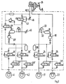
- the invention describes a concrete solution of an electronic brake force distribution control, whereby in the basic configuration only wheel speed sensors and pressure sensors for the pressure rear and front axles are required.
- a solenoid valve 7 separates the rear axle brake circuit from the master brake cylinder when braking, another solenoid valve 8 connects a pressure generator 9 (pump with motor, pressure chamber and pressure relief valve) to the rear wheel brakes connected at 10a and 10b to build up pressure.
- a pressure generator 9 pump with motor, pressure chamber and pressure relief valve
- Inlet valves 11 and 12 and an outlet valve 13 are used for anti-lock control and for ASR.
- the outlet valve 13 is also used for pressure control according to the invention.
- the various pressures (PVA, PHA) are measured with pressure sensors 14 and 15.
- the brakes of the front wheels 21 and 22 are connected to one master brake cylinder of the brake unit 26 via ABS inlet valves 24 and 25.
- Exhaust valves 27 and 28 are assigned to the two inlet valves 24 and 25, which temporarily release pressure to a storage chamber 29 in the ABS case.
- a pressure relief valve 33 is connected in parallel to the throttle parts.
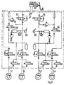
- the hydraulic circuit associated with the driven rear wheels 41 and 42, which is connected to the second master brake cylinder of the brake assembly 26, is constructed in almost completely the same way.
- a changeover valve 43 and a charging valve 44 are also provided.
- valves 43 and 44 switch over, the pump 30 starts and generates a brake pressure.
- the brake pressure on the wheels 41 and 42 is modulated by the valves 24 to 28.
- the valves 43 and 44 must be in the position not shown.
- the return pump 30 'and the valves 43 and 44 can also be used for the pressure variation according to the invention.
- Pressure sensors 45 and 46 are also provided here.
- Fig. 3 differs from Fig. 2 in that the brakes of diagonally lying wheels 51 and 52 or 53 and 54 each belong to a brake circuit.
- the braking pressure of the wheel of the driven axle which first shows the tendency to rotate, is modulated by incorporating a changeover valve (55) and a loading valve (56).
- both pumps, both changeover valves 55 and both charging valves 56 must now operate synchronously.
- pressure sensors 57 to 59 are required.
- FIG. 4 shows the block diagram of a control loop. It essentially consists of a wheel speed control loop, which has the task of setting a detected speed difference between the fastest front wheel and the slowest rear wheel to a specified target value and a subordinate pressure control loop, which sets a calculated target pressure (manipulated variable of the wheel speed controller) on the rear axle.
- a brake pedal 60 which directly pressurizes the brakes 61 of the front axle.
- the faster wheel is selected from the braked front wheels.
- the difference of the speed of the fastest front wheel with the selected slowest rear wheel is formed in a difference former 63; this difference ⁇ V is compared with a target value ⁇ V s in a difference generator 64.
- the storage of the target signal is fed to a wheel speed controller 65, which determines a target pressure therefrom.
- the difference between the setpoint pressure and the pressure pha prevailing at the brakes of the rear wheels are compared in a difference generator 66, the storage being fed to a pressure regulator 67, which uses this to determine control signals for the solenoid valve (s) 68 of the rear wheels.
- the resulting brake pressure acts on the rear wheels 70 via the brakes.
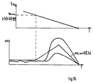
- Figure 5 shows a more detailed illustrated embodiment. Dimensions are indicated by dashed performances.
- ABS 100 is shown there as a block. Below this are blocks for the pulse width modulation (101a) of the valves, the magnetic valves (102a), the brakes (103a) and for the wheels (104a) of the front axle and corresponding blocks (101b, 102b, 103b, 104b) for the rear axle.
- the pressure modulation on the front axle is only considered with ABS control.
- a switching device 105 is controlled by a monitoring block 106, which can distinguish the ABS case from the normal braking case and then actuates the changeover switch 105.
- the difference between the fastest front wheel and the slowest rear wheel is also determined here via PT 1 filtering (low pass) (comparator 80).
- the two front wheels are subjected to stricter filtering since there is no pressure modulation on the front axle in the partial braking area under consideration, and thus the front wheel speeds serve as a reference for the rear wheel speeds.
- This variable ⁇ V thus formed is compared with a target value ⁇ V s to be determined depending on the driving situation in a further comparator 81, and the deviation ⁇ V is fed to a wheel speed control amplifier 82.
- K D is the control gain for the differential component.
- K D K D on (> 0) for ⁇ V ⁇ ⁇ V max
- K D K D ab ( ⁇ 0) for ( ⁇ V ⁇ > ⁇ V max) ⁇ ( ⁇ V ⁇ 0)
- KD 0 for ( ⁇ V ⁇ V max) ⁇ ( ⁇ V ⁇ 0) ⁇ ( ⁇ V ⁇ > 0)
- V ⁇ ⁇ V (K) - ⁇ V (K-1)
- the controller gain is adapted in accordance with the current extension of the stretcher.
- the corrected output signal p s - corr. of the wheel speed controller 82 is then fed into a pressure control circuit (66-68 in FIG. 4; 85-88 and 101b and 102b in FIG. 5) in which the measured HA pressure is set to this p s -corr.
- the regulated HA pressure p-ha now acts on the controlled system, which includes the systems rear wheel brakes, rear wheels, tires and road.
- the two rear wheel speeds form the output variables of the route.
- the measured wheel speed signal of the slower rear wheel is compared with that of the faster front wheel and the deviation is fed to the comparator 81.
- the measured front axle pressure p-va (sensors 4, or 46 or 57) becomes the relationship
- an upper limit for the rear axle target pressure ps, corr determined in the wheel speed controller is determined
- the applied rear axle pressure is regulated to the target pressure p-corr determined in the wheel speed controller.
- the measured rear axle pressure p-ha is compared with the calculated target pressure p-corr in comparator 91 and this difference is fed to a pressure regulator 85 which has a proportional-integral transmission behavior.
- the controlled system here includes the component rear axle valve. Since, in accordance with the pressure-volume core line of the brake system, the pressure change achieved at a specific valve actuation time depends on the pressure level in the wheel brake cylinder itself and on the temperature, this pressure gradient is determined in an identification element 95 according to the following relationships: A distinction must be made here between pressure build-up and pressure reduction, because different pressure change speeds act. This stretching gain, determined according to the above equations, is used as the reciprocal value for the proportional gain of the pressure regulator 85 (gain correction block 86).
- the control law of the pressure regulator thus has the following appearance:
- the valve response times tp, tm (from the estimation block 87) that apply to pressure build-up and pressure reduction are taken into account in an adder 88 by adding to the calculated net valve actuation time.
- the valve response times are determined in block 87 by means of a (strong) 1st order filter according to the relationships (ktp and ktm are between 1 and 5 in the range). estimated and updated.
- ktp u. ktm Gain factors that have to be set in the driving test with regard to good control behavior of the pressure regulator.
- This calculation of the valve response times has the essential advantage that scatter in the valve response times and time-changing response times (eg due to "valve aging") are taken into account and corrected accordingly.
- Switch 105 can be used to switch between the pressure control and the ABS control for the rear axle.
- the following transition logic applies: In the partial braking range, ie if no front wheel has yet reached the ABS threshold, the HA is governed according to the invention.
- Conditions for entering ABS control are: Only when a front wheel is already in ABS control and the other front wheel has already requested a certain filter time pressure reduction is it switched over.
- Conditions for getting out of ABS are: If the calculated valve actuation time of a front wheel exceeds the maximum opening time (cycle time; here: 20 ms) over a certain time (ie pre-pressure is too low or when both front wheels have fallen below a certain minimum speed, it shifts down.
- Both algorithms ABS and pressure control
- ABS and pressure control are preferably always run through - both in the partial braking area and in the ABS case and during the respective transitions.
- the decisive valve actuation time that is to say either the one calculated in the ABS controller or the one calculated in the pressure controller, is then used to actuate the valve drivers.
Landscapes
- Engineering & Computer Science (AREA)
- Physics & Mathematics (AREA)
- Fluid Mechanics (AREA)
- Transportation (AREA)
- Mechanical Engineering (AREA)
- Regulating Braking Force (AREA)
- Hydraulic Control Valves For Brake Systems (AREA)
Applications Claiming Priority (2)
| Application Number | Priority Date | Filing Date | Title |
|---|---|---|---|
| DE4112388 | 1991-04-16 | ||
| DE4112388A DE4112388A1 (de) | 1991-04-16 | 1991-04-16 | Bremsdruckregelanlage fuer ein fahrzeug |
Publications (2)
| Publication Number | Publication Date |
|---|---|
| EP0509237A1 true EP0509237A1 (fr) | 1992-10-21 |
| EP0509237B1 EP0509237B1 (fr) | 1995-12-20 |
Family
ID=6429695
Family Applications (1)
| Application Number | Title | Priority Date | Filing Date |
|---|---|---|---|
| EP92104233A Expired - Lifetime EP0509237B1 (fr) | 1991-04-16 | 1992-03-12 | Système régulateur de pression des freins d'un véhicule |
Country Status (4)
| Country | Link |
|---|---|
| US (1) | US5281012A (fr) |
| EP (1) | EP0509237B1 (fr) |
| JP (2) | JPH05116608A (fr) |
| DE (2) | DE4112388A1 (fr) |
Cited By (7)
| Publication number | Priority date | Publication date | Assignee | Title |
|---|---|---|---|---|
| EP0601480A1 (fr) * | 1992-12-07 | 1994-06-15 | KNORR-BREMSE SYSTEME FÜR NUTZFAHRZEUGE GmbH | Dispositif de contrôle automatique du freinage en fonction de la charge pour véhicule utilitaire |
| WO1994013517A1 (fr) * | 1992-12-11 | 1994-06-23 | Robert Bosch Gmbh | Systeme de freinage |
| FR2699487A1 (fr) * | 1992-12-23 | 1994-06-24 | Bosch Gmbh Robert | Installation de freinage pour véhicule automobile avec distribution de la pression de freinage sur les essieux de véhicules routiers. |
| FR2714006A1 (fr) * | 1993-12-18 | 1995-06-23 | Bosch Gmbh Robert | Système de freinage hydraulique pour véhicules routiers, notamment des voitures particulières. |
| WO1996010507A1 (fr) * | 1994-09-30 | 1996-04-11 | Itt Automotive Europe Gmbh | Systeme de freinage hydraulique et procede de regulation de pression |
| WO1998025805A1 (fr) * | 1996-12-11 | 1998-06-18 | Robert Bosch Gmbh | Procede et dispositif de commande de la repartition de la force de freinage dans un vehicule |
| EP0768965B1 (fr) * | 1995-03-24 | 2000-05-03 | Robert Bosch Gmbh | Procede et dispositif de commande du systeme de freinage d'un vehicule |
Families Citing this family (42)
| Publication number | Priority date | Publication date | Assignee | Title |
|---|---|---|---|---|
| US5547264A (en) * | 1992-11-04 | 1996-08-20 | Aisin Seiki Kabushiki Kaisha | Braking force distribution control system |
| DE4309243C2 (de) * | 1993-03-23 | 2003-07-03 | Continental Teves Ag & Co Ohg | Bremsanlage mit elektronischer Steuerung der Bremskraftverteilung |
| DE4327208A1 (de) * | 1993-08-13 | 1995-02-16 | Teves Gmbh Alfred | Hydraulische Zweikreisbremsanlage |
| DE4334838A1 (de) * | 1993-10-13 | 1995-04-20 | Teves Gmbh Alfred | Bremsanlage mit elektronischer Blockierschutzregelung |
| DE4417935A1 (de) * | 1994-05-21 | 1995-11-23 | Teves Gmbh Alfred | Schaltungsanordnung für eine Bremsanlage mit elektronischer Regelung der Bremskraftverteilung |
| US5487598A (en) * | 1994-12-12 | 1996-01-30 | Alliedsignal Inc. | Variable duty cycle antilock braking system with accelerometer |
| DE19511161A1 (de) * | 1995-03-27 | 1996-10-02 | Bosch Gmbh Robert | Bremssystem für ein Kraftfahrzeug |
| DE19511152A1 (de) | 1995-03-27 | 1996-10-02 | Bosch Gmbh Robert | Verfahren und Vorrichtung zur Steuerung der Bremsanlage eines Fahrzeugs |
| DE19518206B4 (de) * | 1995-05-18 | 2005-10-13 | Robert Bosch Gmbh | Verfahren und Vorrichtung zur Steuerung der Bremsanlage eines Fahrzeugs |
| US5632535A (en) * | 1995-08-28 | 1997-05-27 | Kelsey-Hayes Company | Dynamic rear proportioning brake system |
| DE19541601B4 (de) * | 1995-11-08 | 2007-08-09 | Robert Bosch Gmbh | Verfahren und Vorrichtung zur Steuerung der Bremsanlage eines Fahrzeugs |
| US6474751B1 (en) | 1995-12-26 | 2002-11-05 | Denso Corporation | Hydraulic circuit having a rotary type pump and brake apparatus for a vehicle provided with the same |
| US6142581A (en) * | 1995-12-26 | 2000-11-07 | Denso Corporation | Hydraulic circuit having a rotary type pump and brake apparatus for a vehicle provided with the same |
| EP1026059B1 (fr) * | 1995-12-26 | 2005-11-02 | Denso Corporation | Appareil de contrôle de freinage pour un véhicule |
| DE19614630A1 (de) * | 1996-04-13 | 1997-10-16 | Teves Gmbh Alfred | Bremsanlage mit elektronischer Bremskraftverteilung |
| EP0803421B1 (fr) * | 1996-04-26 | 2001-11-07 | Denso Corporation | Dispositif de freinage pour un véhicule |
| DE19653230B4 (de) * | 1996-12-20 | 2012-03-15 | Robert Bosch Gmbh | Verfahren und Vorrichtung zur Steuerung der Bremsanlage eines Fahrzeugs |
| DE19701070A1 (de) * | 1997-01-15 | 1998-07-16 | Bosch Gmbh Robert | Hydraulische Fahrzeugbremsanlage |
| DE19705619A1 (de) | 1997-02-14 | 1998-08-20 | Bosch Gmbh Robert | Verfahren und Vorrichtung zur Steuerung der Bremskraftverteilung bei einem Kraftfahrzeug |
| DE69729717T2 (de) * | 1997-03-07 | 2005-08-04 | Same Deutz-Fahr Group S.P.A., Treviglio | Bremssteuerungssystem für landwirtschaftliche Traktoren |
| DE19712889A1 (de) * | 1997-03-27 | 1998-10-01 | Bosch Gmbh Robert | Verfahren und Vorrichtung zur Ermittlung einer den Systemdruck in einem Bremskreis beschreibenden Größe |
| JPH10278767A (ja) * | 1997-04-09 | 1998-10-20 | Akebono Brake Ind Co Ltd | ブレーキ液圧制御装置 |
| DE19749005A1 (de) | 1997-06-30 | 1999-01-07 | Bosch Gmbh Robert | Verfahren und Vorrichtung zur Regelung von die Fahrzeugbewegung repräsentierenden Bewegungsgrößen |
| DE19733379B4 (de) | 1997-08-01 | 2005-03-10 | Bosch Gmbh Robert | Vorrichtung zur Steuerung einer Bremsanlage |
| GB9811585D0 (en) * | 1998-06-01 | 1998-07-29 | Delphi France Automotive Sys | Method for controlling vehicle behaviour during cornering and a braking system for implementation thereof |
| WO2001019652A1 (fr) * | 1999-09-16 | 2001-03-22 | Robert Bosch Gmbh | Procede et dispositif de stabilisation d'un vehicule equipe d'un systeme de freinage antiblocage de roues |
| DE19955094A1 (de) * | 1999-11-16 | 2001-05-23 | Siemens Ag | Verfahren zur Bremsregelung eines Kraftfahrzeugs und Bremsvorrichtung für ein Kraftfahrzeug |
| GB2360336B (en) * | 2000-03-14 | 2004-02-04 | Rover Group | Vehicle braking |
| JP2002037044A (ja) * | 2000-07-27 | 2002-02-06 | Aisin Seiki Co Ltd | 車両の前後制動力配分制御装置 |
| DE10234366B3 (de) * | 2002-07-27 | 2004-03-04 | Daimlerchrysler Ag | Bremsdrucksteuervorrichtung |
| US20050067884A1 (en) * | 2003-09-25 | 2005-03-31 | Clark James R. | Brake balance system for tandem axles |
| EP1791740B1 (fr) * | 2004-09-24 | 2011-03-23 | Continental Teves AG & Co. oHG | Procede pour assister un dispositif de freinage en cas de baisse d'efficacite du systeme de freinage du vehicule |
| US7809486B2 (en) * | 2005-04-29 | 2010-10-05 | Kelsey-Hayes Company | Pressure boost for vehicle rear brake circuits |
| NL1030943C2 (nl) * | 2006-01-18 | 2007-07-19 | Tomtom Int Bv | Werkwijze voor het opslaan van de positie van een geparkeerd voertuig en navigatieapparaat dat daarvoor is ingericht. |
| JP4413931B2 (ja) * | 2007-01-18 | 2010-02-10 | 株式会社日立製作所 | 自動車及び自動車の制御装置 |
| DE102008041353A1 (de) * | 2008-08-19 | 2010-02-25 | Robert Bosch Gmbh | Verfahren zur Kompensation von Volumenänderungen eines Hydraulikfluids in einer hydraulischen Betätigungseinrichtung zur Betätigung einer Kupplung, sowie hydraulische Betätigungseinrichtung |
| US8868281B2 (en) * | 2010-10-28 | 2014-10-21 | GM Global Technology Operations LLC | Understeer assessment for vehicles |
| KR102111909B1 (ko) * | 2013-11-21 | 2020-05-18 | 현대모비스 주식회사 | 전자식 유압 브레이크 시스템 |
| DE102015010400A1 (de) | 2015-08-11 | 2017-02-16 | Günter Fendt | Bremsvorrichtung mit aktiver Niveauregelung für ein Fahrzeug, sowie Verfahren für eine Bremsvorrichtung mit aktiver Niveauregelung |
| DE102016201179B4 (de) * | 2016-01-27 | 2021-04-15 | Ford Global Technologies, Llc | Verfahren zum Betreiben eines Bremssystems eines Kraftfahrzeugs sowie Bremssystem für ein Kraftfahrzeug |
| CN113830042A (zh) * | 2020-06-24 | 2021-12-24 | 广州汽车集团股份有限公司 | 一种汽车制动控制方法及系统 |
| US11767003B2 (en) | 2020-12-14 | 2023-09-26 | Continental Automotive Systems, Inc. | By-wire brake system for motor vehicles |
Citations (4)
| Publication number | Priority date | Publication date | Assignee | Title |
|---|---|---|---|---|
| DE3323402A1 (de) * | 1983-04-07 | 1984-10-18 | Alfred Teves Gmbh, 6000 Frankfurt | Bremsanlage fuer kraftfahrzeuge |
| US4962971A (en) * | 1987-11-19 | 1990-10-16 | Akebono Brake Industry Co., Ltd. | Anti-skid control system for motor vehicles |
| DE3923955A1 (de) * | 1989-07-19 | 1991-01-31 | Lucas Ind Plc | Bremsvorrichtung fuer ein zweiachsiges fahrzeug |
| DE4007360A1 (de) * | 1990-03-08 | 1991-09-12 | Daimler Benz Ag | Verfahren zur bremsdruckverteilung auf die achsen eines kraftfahrzeugs mit abs-druckmittelbremse |
Family Cites Families (24)
| Publication number | Priority date | Publication date | Assignee | Title |
|---|---|---|---|---|
| US3574415A (en) * | 1968-08-26 | 1971-04-13 | Rockwell Standard Co | Brake system |
| FR2067882A5 (fr) * | 1969-11-20 | 1971-08-20 | Dba | |
| US3608978A (en) * | 1970-05-01 | 1971-09-28 | Rockwell Standard Co | Antiskid brake control |
| BE794514A (fr) * | 1972-02-08 | 1973-05-16 | Citroen Sa | Perfectionnements apportes aux dispositifs de commande de freinage d'un vehicule |
| DE2327508A1 (de) * | 1973-05-30 | 1974-12-19 | Teldix Gmbh | Fahrzeugbremsanlage |
| DE2411096A1 (de) * | 1974-03-08 | 1975-09-18 | Daimler Benz Ag | Verfahren und einrichtung zur ansteuerung einer zweikreis-bremsanlage fuer kraftfahrzeuge |
| DE3240275A1 (de) * | 1982-10-30 | 1984-05-03 | Robert Bosch Gmbh, 7000 Stuttgart | Einrichtung zur lastabhaengigen bremskraftregelung |
| DE3301948A1 (de) * | 1983-01-21 | 1984-07-26 | Alfred Teves Gmbh, 6000 Frankfurt | Verfahren und vorrichtung zur steuerung der bremskraftverteilung |
| DE3302642C2 (de) * | 1983-01-27 | 1986-09-04 | Daimler-Benz Ag, 7000 Stuttgart | Antiblockiersystem für ein Zweirad-Straßenfahrzeug mit hydraulischer Zweikreis-Bremsanlage |
| DE3306611A1 (de) * | 1983-02-25 | 1984-08-30 | Alfred Teves Gmbh, 6000 Frankfurt | Verfahren und vorrichtung zur steuerung der bremskraftverteilung |
| JPH0613287B2 (ja) * | 1984-05-21 | 1994-02-23 | 日産自動車株式会社 | 車両用制動力制御装置 |
| DE3602432A1 (de) * | 1986-01-28 | 1987-07-30 | Bosch Gmbh Robert | Antiblockierregelsystem |
| DE3700742C1 (de) * | 1987-01-13 | 1988-06-23 | Hans Deinlein-Kalb | Regelsystem fuer die Anfahr-und Bremsschlupfregelung von Zweiradfahrzeugen |
| DE3721210A1 (de) * | 1987-06-26 | 1989-01-05 | Rexroth Mannesmann Gmbh | Anordnung zum regeln des bremsdrucks |
| DE3723916A1 (de) * | 1987-07-18 | 1989-01-26 | Daimler Benz Ag | Hydraulische zweikreis-bremsanlage |
| DE3741310A1 (de) * | 1987-12-05 | 1989-06-15 | Bosch Gmbh Robert | Blockierschutz- und antriebsschlupfregelanlage |
| DE3802133A1 (de) * | 1988-01-26 | 1989-08-03 | Daimler Benz Ag | Antriebs-schlupf-regeleinrichtung |
| DE3814045C2 (de) * | 1988-04-26 | 1996-08-08 | Teves Gmbh Alfred | Schlupfgeregelte hydraulische Bremsanlage |
| US4850650A (en) * | 1988-09-02 | 1989-07-25 | General Motors Corporation | Hierarchical brake controller |
| US5042884A (en) * | 1988-11-25 | 1991-08-27 | Lucas Industries Public Limited Company | Hydraulic braking systems for vehicles |
| JP2980920B2 (ja) * | 1989-08-03 | 1999-11-22 | 日本エービーエス株式会社 | 車両用液圧ブレーキ制御装置 |
| DE4010410A1 (de) * | 1990-03-31 | 1991-10-02 | Bosch Gmbh Robert | Hydraulische zweikreisbremsanlage |
| JP2650459B2 (ja) * | 1990-04-06 | 1997-09-03 | トヨタ自動車株式会社 | 加速スリップ制御装置 |
| DE4016560A1 (de) * | 1990-05-23 | 1991-11-28 | Bosch Gmbh Robert | Hydraulische bremsanlage |
-
1991
- 1991-04-16 DE DE4112388A patent/DE4112388A1/de not_active Withdrawn
-
1992
- 1992-03-12 EP EP92104233A patent/EP0509237B1/fr not_active Expired - Lifetime
- 1992-03-12 DE DE59204719T patent/DE59204719D1/de not_active Expired - Lifetime
- 1992-04-16 JP JP4096654A patent/JPH05116608A/ja active Pending
- 1992-04-16 US US07/870,047 patent/US5281012A/en not_active Expired - Lifetime
-
2003
- 2003-09-04 JP JP2003270996U patent/JP2004000005U/ja active Pending
Patent Citations (4)
| Publication number | Priority date | Publication date | Assignee | Title |
|---|---|---|---|---|
| DE3323402A1 (de) * | 1983-04-07 | 1984-10-18 | Alfred Teves Gmbh, 6000 Frankfurt | Bremsanlage fuer kraftfahrzeuge |
| US4962971A (en) * | 1987-11-19 | 1990-10-16 | Akebono Brake Industry Co., Ltd. | Anti-skid control system for motor vehicles |
| DE3923955A1 (de) * | 1989-07-19 | 1991-01-31 | Lucas Ind Plc | Bremsvorrichtung fuer ein zweiachsiges fahrzeug |
| DE4007360A1 (de) * | 1990-03-08 | 1991-09-12 | Daimler Benz Ag | Verfahren zur bremsdruckverteilung auf die achsen eines kraftfahrzeugs mit abs-druckmittelbremse |
Cited By (8)
| Publication number | Priority date | Publication date | Assignee | Title |
|---|---|---|---|---|
| EP0601480A1 (fr) * | 1992-12-07 | 1994-06-15 | KNORR-BREMSE SYSTEME FÜR NUTZFAHRZEUGE GmbH | Dispositif de contrôle automatique du freinage en fonction de la charge pour véhicule utilitaire |
| WO1994013517A1 (fr) * | 1992-12-11 | 1994-06-23 | Robert Bosch Gmbh | Systeme de freinage |
| FR2699487A1 (fr) * | 1992-12-23 | 1994-06-24 | Bosch Gmbh Robert | Installation de freinage pour véhicule automobile avec distribution de la pression de freinage sur les essieux de véhicules routiers. |
| FR2714006A1 (fr) * | 1993-12-18 | 1995-06-23 | Bosch Gmbh Robert | Système de freinage hydraulique pour véhicules routiers, notamment des voitures particulières. |
| WO1996010507A1 (fr) * | 1994-09-30 | 1996-04-11 | Itt Automotive Europe Gmbh | Systeme de freinage hydraulique et procede de regulation de pression |
| US6082830A (en) * | 1994-09-30 | 2000-07-04 | Itt Mfg Emterprises Inc | Brake system having variable pump pressure control and method of pressure control |
| EP0768965B1 (fr) * | 1995-03-24 | 2000-05-03 | Robert Bosch Gmbh | Procede et dispositif de commande du systeme de freinage d'un vehicule |
| WO1998025805A1 (fr) * | 1996-12-11 | 1998-06-18 | Robert Bosch Gmbh | Procede et dispositif de commande de la repartition de la force de freinage dans un vehicule |
Also Published As
| Publication number | Publication date |
|---|---|
| EP0509237B1 (fr) | 1995-12-20 |
| JPH05116608A (ja) | 1993-05-14 |
| US5281012A (en) | 1994-01-25 |
| DE59204719D1 (de) | 1996-02-01 |
| DE4112388A1 (de) | 1992-10-22 |
| JP2004000005U (ja) | 2004-02-05 |
Similar Documents
| Publication | Publication Date | Title |
|---|---|---|
| EP0509237B1 (fr) | Système régulateur de pression des freins d'un véhicule | |
| DE60311566T2 (de) | Fahrzeugbremssystem und Verfahren zu dessen Regelung | |
| DE112005001226B4 (de) | Bremskraftregelungssystem für Fahrzeuge | |
| DE69229634T2 (de) | Verfahren und vorrichtung zur regelung der bremskraft der hinterräder | |
| EP1888387B1 (fr) | Circuit de freinagepor un système de freinage hydraulique, système de freinage avec un tel circuit de freinage et une méthode de commande d'un système de freinage hydraulique pour un véhicule terrestre | |
| DE102016013054A1 (de) | Verfahren zum Einstellen von Bremsdrücken eines Fahrzeugs, Bremsanlage zur Durchführung des Verfahrens sowie Fahrzeug | |
| DE102006000145A1 (de) | Bremssteuervorrichtung für ein Fahrzeug | |
| DE102005013741A1 (de) | Steuervorrichtung zum Automatischen Abbremsen für ein Fahrzeug | |
| DE4121747A1 (de) | Antriebs-schlupf-regelung fuer ein motorfahrzeug | |
| DE102009046629A1 (de) | Steuervorrichtung für ein Bremsgerät | |
| DE19502384A1 (de) | Verfahren zur Berechnung geschätzter Fahrzeuggeschwindigkeiten | |
| DE69508164T2 (de) | Bremsdruckregeleinrichtung für Kraftfahrzeuge | |
| DE69502298T2 (de) | Verfahren zur Berechnung der Radreferenzgeschwindigkeit bei einer Antiblockierbremssystem | |
| DE19838179A1 (de) | Steuervorrichtung für das Fahrzeug-Fahrverhalten | |
| DE10225870B4 (de) | Fahrzeugbremsregelvorrichtung und -Verfahren | |
| DE4208581A1 (de) | Bremsdruck-steuereinrichtung | |
| DE4128087A1 (de) | Bremsdruckregelanlage fuer ein fahrzeug | |
| DE69208433T2 (de) | Verfahren zur Regelung der Hinterradbremskraft und Vorrichtung dafür | |
| DE19624491C2 (de) | Vorrichtung zum Steuern der Bremskraftverteilung eines Fahrzeugs | |
| DE19607185A1 (de) | Verfahren zur Sicherstellung eines neutralen Fahrverhaltens bei Kurvenfahrten und gleichzeitigem Lastwechsel | |
| DE19504295A1 (de) | Blockierschutzbremssystem für Fahrzeuge, bei dem ein Austrittsende eines Pumpkanals mit einem Kanal verbunden ist, der einen Hinterradbremszylinder und ein Proportionalventil verbindet | |
| DE19542294B4 (de) | Schlupfregler für eine Antriebsschlupfregelung | |
| DE4105490C2 (de) | Schlupfregelsystem für ein Motorfahrzeug | |
| DE69219489T2 (de) | Traktionssteuersystem für Motorfahrzeuge | |
| DE19834167B4 (de) | Verfahren und Vorrichtung zur Anpassung der Bremsleistung an momentane Rad-Fahrbahn-Kraftschluß-Bedingungen |
Legal Events
| Date | Code | Title | Description |
|---|---|---|---|
| PUAI | Public reference made under article 153(3) epc to a published international application that has entered the european phase |
Free format text: ORIGINAL CODE: 0009012 |
|
| AK | Designated contracting states |
Kind code of ref document: A1 Designated state(s): DE FR IT SE |
|
| 17P | Request for examination filed |
Effective date: 19930326 |
|
| 17Q | First examination report despatched |
Effective date: 19940420 |
|
| GRAA | (expected) grant |
Free format text: ORIGINAL CODE: 0009210 |
|
| AK | Designated contracting states |
Kind code of ref document: B1 Designated state(s): DE FR IT SE |
|
| ET | Fr: translation filed | ||
| REF | Corresponds to: |
Ref document number: 59204719 Country of ref document: DE Date of ref document: 19960201 |
|
| ITF | It: translation for a ep patent filed | ||
| PLBE | No opposition filed within time limit |
Free format text: ORIGINAL CODE: 0009261 |
|
| STAA | Information on the status of an ep patent application or granted ep patent |
Free format text: STATUS: NO OPPOSITION FILED WITHIN TIME LIMIT |
|
| 26N | No opposition filed | ||
| PGFP | Annual fee paid to national office [announced via postgrant information from national office to epo] |
Ref country code: SE Payment date: 20040322 Year of fee payment: 13 |
|
| PG25 | Lapsed in a contracting state [announced via postgrant information from national office to epo] |
Ref country code: IT Free format text: LAPSE BECAUSE OF NON-PAYMENT OF DUE FEES;WARNING: LAPSES OF ITALIAN PATENTS WITH EFFECTIVE DATE BEFORE 2007 MAY HAVE OCCURRED AT ANY TIME BEFORE 2007. THE CORRECT EFFECTIVE DATE MAY BE DIFFERENT FROM THE ONE RECORDED. Effective date: 20050312 |
|
| PG25 | Lapsed in a contracting state [announced via postgrant information from national office to epo] |
Ref country code: SE Free format text: LAPSE BECAUSE OF NON-PAYMENT OF DUE FEES Effective date: 20050313 |
|
| EUG | Se: european patent has lapsed | ||
| PGFP | Annual fee paid to national office [announced via postgrant information from national office to epo] |
Ref country code: FR Payment date: 20110401 Year of fee payment: 20 |
|
| PGFP | Annual fee paid to national office [announced via postgrant information from national office to epo] |
Ref country code: DE Payment date: 20110525 Year of fee payment: 20 |
|
| REG | Reference to a national code |
Ref country code: DE Ref legal event code: R071 Ref document number: 59204719 Country of ref document: DE |
|
| REG | Reference to a national code |
Ref country code: DE Ref legal event code: R071 Ref document number: 59204719 Country of ref document: DE |
|
| PG25 | Lapsed in a contracting state [announced via postgrant information from national office to epo] |
Ref country code: DE Free format text: LAPSE BECAUSE OF EXPIRATION OF PROTECTION Effective date: 20120313 |