EP0508941A1 - Werkzeug zur Zerspanung von Werkstoffen - Google Patents
Werkzeug zur Zerspanung von Werkstoffen Download PDFInfo
- Publication number
- EP0508941A1 EP0508941A1 EP92810107A EP92810107A EP0508941A1 EP 0508941 A1 EP0508941 A1 EP 0508941A1 EP 92810107 A EP92810107 A EP 92810107A EP 92810107 A EP92810107 A EP 92810107A EP 0508941 A1 EP0508941 A1 EP 0508941A1
- Authority
- EP
- European Patent Office
- Prior art keywords
- layer
- diamond
- tool
- hard material
- material layer
- Prior art date
- Legal status (The legal status is an assumption and is not a legal conclusion. Google has not performed a legal analysis and makes no representation as to the accuracy of the status listed.)
- Granted
Links
Images
Classifications
-
- C—CHEMISTRY; METALLURGY
- C23—COATING METALLIC MATERIAL; COATING MATERIAL WITH METALLIC MATERIAL; CHEMICAL SURFACE TREATMENT; DIFFUSION TREATMENT OF METALLIC MATERIAL; COATING BY VACUUM EVAPORATION, BY SPUTTERING, BY ION IMPLANTATION OR BY CHEMICAL VAPOUR DEPOSITION, IN GENERAL; INHIBITING CORROSION OF METALLIC MATERIAL OR INCRUSTATION IN GENERAL
- C23C—COATING METALLIC MATERIAL; COATING MATERIAL WITH METALLIC MATERIAL; SURFACE TREATMENT OF METALLIC MATERIAL BY DIFFUSION INTO THE SURFACE, BY CHEMICAL CONVERSION OR SUBSTITUTION; COATING BY VACUUM EVAPORATION, BY SPUTTERING, BY ION IMPLANTATION OR BY CHEMICAL VAPOUR DEPOSITION, IN GENERAL
- C23C30/00—Coating with metallic material characterised only by the composition of the metallic material, i.e. not characterised by the coating process
- C23C30/005—Coating with metallic material characterised only by the composition of the metallic material, i.e. not characterised by the coating process on hard metal substrates
-
- B—PERFORMING OPERATIONS; TRANSPORTING
- B23—MACHINE TOOLS; METAL-WORKING NOT OTHERWISE PROVIDED FOR
- B23B—TURNING; BORING
- B23B51/00—Tools for drilling machines
- B23B51/04—Drills for trepanning
-
- B—PERFORMING OPERATIONS; TRANSPORTING
- B23—MACHINE TOOLS; METAL-WORKING NOT OTHERWISE PROVIDED FOR
- B23B—TURNING; BORING
- B23B2222/00—Materials of tools or workpieces composed of metals, alloys or metal matrices
- B23B2222/28—Details of hard metal, i.e. cemented carbide
-
- B—PERFORMING OPERATIONS; TRANSPORTING
- B23—MACHINE TOOLS; METAL-WORKING NOT OTHERWISE PROVIDED FOR
- B23B—TURNING; BORING
- B23B2226/00—Materials of tools or workpieces not comprising a metal
- B23B2226/31—Diamond
- B23B2226/315—Diamond polycrystalline [PCD]
-
- B—PERFORMING OPERATIONS; TRANSPORTING
- B23—MACHINE TOOLS; METAL-WORKING NOT OTHERWISE PROVIDED FOR
- B23B—TURNING; BORING
- B23B2228/00—Properties of materials of tools or workpieces, materials of tools or workpieces applied in a specific manner
- B23B2228/10—Coatings
-
- B—PERFORMING OPERATIONS; TRANSPORTING
- B23—MACHINE TOOLS; METAL-WORKING NOT OTHERWISE PROVIDED FOR
- B23B—TURNING; BORING
- B23B2240/00—Details of connections of tools or workpieces
- B23B2240/08—Brazed connections
-
- B—PERFORMING OPERATIONS; TRANSPORTING
- B23—MACHINE TOOLS; METAL-WORKING NOT OTHERWISE PROVIDED FOR
- B23B—TURNING; BORING
- B23B2251/00—Details of tools for drilling machines
- B23B2251/50—Drilling tools comprising cutting inserts
-
- Y—GENERAL TAGGING OF NEW TECHNOLOGICAL DEVELOPMENTS; GENERAL TAGGING OF CROSS-SECTIONAL TECHNOLOGIES SPANNING OVER SEVERAL SECTIONS OF THE IPC; TECHNICAL SUBJECTS COVERED BY FORMER USPC CROSS-REFERENCE ART COLLECTIONS [XRACs] AND DIGESTS
- Y10—TECHNICAL SUBJECTS COVERED BY FORMER USPC
- Y10T—TECHNICAL SUBJECTS COVERED BY FORMER US CLASSIFICATION
- Y10T407/00—Cutters, for shaping
- Y10T407/27—Cutters, for shaping comprising tool of specific chemical composition
-
- Y—GENERAL TAGGING OF NEW TECHNOLOGICAL DEVELOPMENTS; GENERAL TAGGING OF CROSS-SECTIONAL TECHNOLOGIES SPANNING OVER SEVERAL SECTIONS OF THE IPC; TECHNICAL SUBJECTS COVERED BY FORMER USPC CROSS-REFERENCE ART COLLECTIONS [XRACs] AND DIGESTS
- Y10—TECHNICAL SUBJECTS COVERED BY FORMER USPC
- Y10T—TECHNICAL SUBJECTS COVERED BY FORMER US CLASSIFICATION
- Y10T408/00—Cutting by use of rotating axially moving tool
- Y10T408/78—Tool of specific diverse material
-
- Y—GENERAL TAGGING OF NEW TECHNOLOGICAL DEVELOPMENTS; GENERAL TAGGING OF CROSS-SECTIONAL TECHNOLOGIES SPANNING OVER SEVERAL SECTIONS OF THE IPC; TECHNICAL SUBJECTS COVERED BY FORMER USPC CROSS-REFERENCE ART COLLECTIONS [XRACs] AND DIGESTS
- Y10—TECHNICAL SUBJECTS COVERED BY FORMER USPC
- Y10T—TECHNICAL SUBJECTS COVERED BY FORMER US CLASSIFICATION
- Y10T408/00—Cutting by use of rotating axially moving tool
- Y10T408/81—Tool having crystalline cutting edge
Definitions
- the invention relates to a tool with a carrier body for a diamond-like layer.
- the carrier body with hard metal bodies.
- the tools can be milling, drilling, turning or chiseling tools, the carrier bodies each having an appropriately coordinated shape.
- the hard metal bodies can be connected, for example via solder connections, to the relevant end faces of the carrier bodies.
- the hard metal body with one or more layers of metal boron nitride, the boron concentration being kept below a certain value.
- the layers act as a kind of diffusion barrier. It is essential that the hardness of the applied layer is harder than the hard metal underneath, which means that the layer must also be self-supporting. In order to adequately comply with this self-supporting property, the layer must have a relatively large thickness in the range from 1 to 10 micrometers. This large thickness is associated with internal stress, which is why the layer is susceptible to breakage and cracking, which is promoted in particular by giving in to the softer surface.
- the diamond-like layer can be present in various ways. For example, it can be applied to the carrier body using the known PVD or CVD processes. In addition, it is possible to arrange diamond grains individually on the carrier body, for example by means of soldering or a galvanic process. However, polycrystalline diamond flakes, for example soldered onto the carrier body, are widespread, these polycrystalline diamond flakes having a hard metal base body which has the diamond grains in a composite or as a diamond layer.
- iron alloys cannot be processed with them.
- an interaction between the diamond-like layer as carbon and the iron occurs in such a way that chemical wear of the layer takes place.
- Such an interaction can occur, for example, when concrete has to be processed with iron reinforcements and a tool provided with such a diamond-like layer hits the iron reinforcements. Since such iron reinforcements can be expected in most components made of concrete, tools with diamond-like layers cannot be used for such cases.
- the invention has for its object to provide a tool based on the use of diamond-like layers, with which iron alloys or materials mixed with iron alloys can also be machined.
- the object is achieved in that at least the diamond-like layer is coated with a thin hard material layer acting as a carbon diffusion barrier.
- the hard material layer forms a diffusion barrier. Thanks to this diffusion barrier, there is no interaction between the diamond-like layer and the iron alloy, so that the disadvantageously described chemical wear does not occur. Since the diamond-like layer with its extraordinarily high hardness serves as a base for the hard material layer, the hard material layer does not have to be self-supporting, so that its thickness can be chosen to be very thin, for example in the range from 0.1 to 1 micrometer. Thanks to this extraordinarily thin hard material layer, only low residual stresses occur, so that cracking, as would occur with thicker layers, is avoided. Due to the lack of interaction between the diamond-like layer and iron, the coefficient of friction also drops, which promotes the "flow" of the "chips".
- the diamond-like layer of the tool is coated with the hard material layer.
- other parts of the tool can also be coated with the hard material layer, for example when using polycrystalline diamond plates, also a part of the hard metal base body.
- Such polycrystalline diamond flakes which are wholly or only partially provided with the hard material layer, are preferably connected to the carrier body by means of soldering, it being possible for there to be recesses matched to the flake on the carrier body.
- the hard material layer preferably has metal nitrides. Titanium nitrides are particularly advantageous as metal nitrides.
- an analogous effect with regard to diffusion barrier is achieved with metal oxides, with aluminum oxides being particularly preferred for economic reasons.
- the hard material layer further preferably contains metal carbides.
- the use of titanium carbides is particularly advantageous from the point of view of achieving high hardness.
- the over-stoichiometric carbon content of the hard material layer resulting from the aforementioned composition examples also has a similar effect to a lubricant, so that the coefficient of friction between the tool and the material to be machined is also thereby reduced.
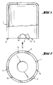
- FIGS. 1 and 2 show a tool designed as a countersink.
- This tool consists of a carrier body 1 which has cutouts 1 a on the end face, within which polycrystalline diamond plates 2 are arranged, facing in the direction of rotation. As shown in particular in FIG. 2, three polycrystalline diamond plates 2 are provided, for example, evenly distributed over the circumference.
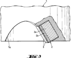
- FIG. 3 shows an enlarged section of the carrier body 1 with recess 1a and polycrystalline diamond plate 2 embedded in the carrier body 1.
- the polycrystalline diamond plate 2 consists of a hard metal base body 2a and a diamond-like layer 2b.
- the diamond-like layer 2b is arranged on the hard metal base body 2a on the side facing in the direction of rotation.
- the diamond-like layer 2b and part of the hard metal base body 2a are coated with a hard material layer 3.
- the arrangement of the hard material layer 3 shown in FIG. 3 is only intended to represent one example. In itself, it is sufficient if only the diamond-like layer 2b is covered by the hard material layer 3. Depending on the manufacturing process, however, the entire polycrystalline diamond plate 2 can also be coated by the hard material layer 3.
- the thickness of the diamond-like layer 2b can be approximately 0.7 mm, the thickness of the hard material layer is approximately 0.1 to 1 micrometer.
Landscapes
- Chemical & Material Sciences (AREA)
- Engineering & Computer Science (AREA)
- Mechanical Engineering (AREA)
- Chemical Kinetics & Catalysis (AREA)
- Materials Engineering (AREA)
- Metallurgy (AREA)
- Organic Chemistry (AREA)
- Cutting Tools, Boring Holders, And Turrets (AREA)
- Polishing Bodies And Polishing Tools (AREA)
- Chemical Vapour Deposition (AREA)
- Crystals, And After-Treatments Of Crystals (AREA)
- Drilling Tools (AREA)
- Turning (AREA)
- Other Surface Treatments For Metallic Materials (AREA)
- Mounting, Exchange, And Manufacturing Of Dies (AREA)
- Earth Drilling (AREA)
Abstract
Description
- Die Erfindung betrifft ein Werkzeug mit Trägerkörper für eine diamantartige Schicht.
- Bei Werkzeugen, die den Zerspanen von Werkstoffen unterschiedlicher Art wie Holz, Gestein, Metallegierungen und dergleichen dienen, ist es bekannt, einen Trägerkörper mit Hartmetallkörpern zu versehen. Bei den Werkzeugen kann es sich um Fräs-, Bohr-, Dreh oder Meisselwerkzeuge handeln, wobei die Trägerkörper jeweils eine entsprechend abgestimmte Form aufweisen. Die Hartmetallkörper können je nach Anwendungsfall beispielsweise über Lötverbindungen mit den jeweils massgebenden Stirnseiten der Trägerkörper verbunden sein.
- Zur Erhöhung der Verschleissfestigkeit ist es beispielsweise aus der EP-A-0 306 077 bekannt, den Hartmetallkörper mit einer oder mehrerer Schichten aus Metall-Bornitrid zu versehen, wobei die Borkonzentration unter einem bestimmten Wert gehalten wird. Die Schichten wirken dabei als eine Art Diffusionssperre. Dabei ist wesentlich, dass die Härte der aufgetragenen Schicht härter ist als das darunter liegende Hartmetall, was dazu führt, dass die Schicht auch selbsttragend sein muss. Um dieser selbsttragenden Eigenschaft ausreichend nachzukommen, muss die Schicht eine relativ grosse Dicke im Bereich von 1 bis 10 Mikrometer aufweisen. Diese grosse Dicke ist mit Eigenspannung verbunden, weshalb die Schicht anfällig auf Bruch und Rissbildung ist, was insbesondere durch Nachgeben der weicheren Unterlage gefördert wird.
- Insbesondere aus der Sicht der hohen Anforderungen hinsichtlich Verschleissfestigkeit sind auf dem Gebiet der Zerspanung von Holz, Aluminiumlegierungen, Gestein und dergleichen vermehrt mit einer diamantartigen Schicht versehene Werkzeuge bekannt geworden. Bei diesen Werkzeugen handelt es sich wiederum um einen Trägerkörper, der entsprechend dem Anwendungsfall ausgebildet ist.
- Die diamantartige Schicht kann in verschiedenartiger Weise vorliegen. So kann sie beispielsweise mittels den bekannten PVD- oder CVD-Verfahren auf den Trägerkörper aufgebracht werden. Darüber hinaus besteht die Möglichkeit, Diamantkörner einzeln, beispielsweise mittels Löten oder einem galvanischen Verfahren auf dem Trägerkörper anzuordnen. Verbreitet sind aber vor allem auf dem Trägerkörper beispielsweise aufgelötete polykristalline Diamantplättchen, wobei diese polykristallinen Diamantplättchen einen Hartmetallgrundkörper aufweisen, welcher die Diamantkörner im Verbund oder als Diamantschicht aufweist.
- Während hinsichtlich Verschleissfestigkeit diamantartige Schichten bei den vorgenannten Anwendungsfällen grosse Vorteile bringen, besteht der Nachteil darin, dass damit Eisenlegierungen nicht bearbeitet werden können. Im Falle der Bearbeitung von Eisenlegierungen tritt eine Wechselwirkung zwischen der diamantartigen Schicht als Kohlenstoffund dem Eisen derart auf, dass ein chemischer Verschleiss der Schicht stattfindet. Eine solche Wechselwirkung kann beispielsweise dann eintreten, wenn Beton mit Eisenarmierungen bearbeitet werden muss und ein mit einer solchen diamantartigen Schicht versehenes Werkzeug auf die Eisenarmierungen trifft. Da mit solchen Eisenarmierungen in den meisten aus Beton bestehenden Bauteilen zu rechnen ist, können mit diamantartigen Schichten versehene Werkzeuge für solche Fälle nicht eingesetzt werden.
- Der Erfindung liegt die Aufgabe zugrunde, ein auf der Verwendung diamantartiger Schichten aufgebautes Werkzeug zu schaffen, mit welchem sich auch Eisenlegierungen bzw. mit Eisenlegierungen versetzte Werkstoffe zerspanen lassen.
- Erfindungsgemäss wird die Aufgabe dadurch gelöst, dass zumindest die diamantartige Schicht mit einer als Kohlenstoff-Diffusionsbarriere wirkenden dünnen Hartstoffschicht überzogen ist.
- Wird ein Werkzeug mit einer diamantartigen Schicht, die in der vorgenannten Weise bearbeitet ist, zum Zerspanen von Eisenlegierungen eingesetzt, bildet die Hartstoffschicht eine Diffusionsbarriere. Dank dieser Diffusionsbarriere findet keine Wechselwirkung zwischen der diamantartigen Schicht und der Eisenlegierung statt, so dass der nachteilig geschilderte chemische Verschleiss ausbleibt. Da als Unterlage für die Hartstoffschicht die diamantartige Schicht mit ihrer ausserordentlich hohen Härte dient, muss die Hartstoffschicht nicht selbsttragend sein, so dass deren Dicke sehr dünn gewählt werden kann, beispielsweise im Bereich von 0,1 bis 1 Mikrometer. Dank dieser ausserordentlich dünnen Hartstoffschicht treten nur geringe Eigenspannungen auf, so dass eine Rissbildung, wie sie bei dickeren Schichten auftreten würde, vermieden wird. Aufgrund des Ausbleibens der Wechselwirkung zwischen diamantartiger Schicht und Eisen sinkt ferner der Reibkoeffizient, was das "Fliessen" der "Späne" fördert.
- An sich reicht es aus, wenn nur die diamantartige Schicht des Werkzeuges mit der Hartstoffschicht überzogen ist. Je nach Verfahren, das zum Aufbringen der Hartstoffschicht verwendet wird, können auch weitere Teile des Werkzeuges, beispielsweise bei Verwendung polykristalliner Diamantplättchen auch ein Teil des Hartmetallgrundkörpers mit der Hartstoffschicht überzogen sein. Solche ganz oder nur teilweise mit der Hartstoffschicht versehene polykristalline Diamantplättchen werden vorzugsweise mittels Löten mit dem Trägerkörper verbunden, wobei gegebenenfalls am Trägerkörper auf das Plättchen abgestimmte Ausnehmungen vorhanden sein können.
- Aus der Sicht der Diffusionssperre weist die Hartstoffschicht vorzugsweise Metall-Nitride auf. Insbesondere wirken sich als Metall-Nitride Titan-Nitride vorteilhaft aus.
- Eine analoge Wirkung hinsichtlich Diffusionssperre wird gemäss einer weiteren Ausführungsform der Erfindung mit Metalloxyden erzielt, anbei sich insbesondere aus wirtschaftlichen Überlegungen Aluminiumoxyde in bevorzugter Weise anbieten.
- Zur Erhöhung der Härte enthält die Hartstoffschicht im weiteren in bevorzugter Weise Metallkarbide. Insbesondere aus der Sicht der Erzielung einer hohen Härte wirkt sich die Verwendung von Titankarbiden vorteilhaft aus.
- Der sich aus den vorgenannten Zusammensetzungsbeispielen ergebende überstöchiometrische Kohlenstoffgehalt der Hartstoffschicht wirkt sich weiterhin ähnlich einem Schmierstoff aus, so dass auch dadurch der Reibungskoeffizient zwischen den Werkzeug und dem zu bearbeitenden Werkstoff herabgesetzt wird.
- Die Erfindung wird nachstehend in beispielhafter Form erläutert. Es zeigen:
- Fig. 1 eine Ansicht eines Werkzeuges in Form eines Dosensenkers mit polykristallinen Diamantplättchen;
- Fig. 2 eine Ansicht des Werkzeuges der Fig. 1 in Richtung A;
- Fig. 3 die Anordnung eines Diamantplättchens entsprechend Fig. 1 in vergrösserter Daratellung.
- Aus den Figuren 1 und 2 ist ein als Dosensenker ausgebildetes Werkzeug ersichtlich. Dieses Werkzeug besteht aus einem Trägerkörper 1, welcher stirnseitig Aussparungen 1a aufweist, innerhalb welcher in Drehrichtung zugewandt polykristalline Diamantplättchen 2 angeordnet sind. wie insbesondere Figur 2 zeigt, sind beispielhaft über den Umfang gleichmässig verteilt drei polykristalline Diamantplättchen 2 vorgesehen.
- Figur 3 zeigt einen vergrösserten Ausschnitt des Trägerkörpers 1 mit Aussparung 1a und im Trägerkörper 1 eingelassenem polykristallinen Diamantplättchen 2. Wie die Figur 3 ferner zeigt, besteht das polykristalline Diamantplättchen 2 aus einem Hartmetallgrundkörper 2a und einer diamantartigen Schicht 2b. Die diamantartige Schicht 2b ist an der in Drehrichtung zugewandten Seite am Hartmetallgrundkörper 2a angeordnet. Die diamantartige Schicht 2b und ein Teil des Hartmetallgrundkörpers 2a sind mit einer Hartstoffschicht 3 überzogen.
- Die in der Figur 3 gezeigte Anordnung der Hartstoffschicht 3 soll nur ein Beispiel darstellen. An sich genügt es, wenn nur die diamantartige Schicht 2b von der Hartstoffschicht 3 überzogen ist. Je nach Herstellungsvorgang kann aber auch das gesamte polykristalline Diamantplättchen 2 von der Hartstoffschicht 3 überzogen sein.
- Während die Dicke der diamantartigen Schicht 2b etwa 0,7 mm betragen kann, beträgt die Dicke der Hartstoffschicht etwa 0,1 bis 1 Mikrometer.
Claims (7)
- Werkzeug mit Trägerkörper (1) für eine diamantartige Schicht (2b), dadurch gekennzeichnet, dass zumindeet die diamantartige Schicht (2b) mit einer als Kohlenstoff-Diffusionsbarriere wirkenden dünnen Hartstoffschicht (3) überzogen ist.
- Werkzeug nach Anspruch 1, dadurch gekennzeichnet, dass die Hartstoffschicht (3) Metall-Nitride aufweist.
- Werkzeug nach Anspruch 2, dadurch gekennzeichnet, dass die Metall-Nitride Titan-Nitride sind.
- Werkzeug nach einem der Ansprüche 1 bis 3, dadurch gekennzeichnet, dass die Hartstoffschicht (3) Metalloxyde aufweist.
- Werkzeug nach Anspruch 4, dadurch gekennzeichnet, dass die Metalloxyde Aluminiumoxyde sind.
- Werkzeug nach einem der Ansprüche 1 bis 5, dadurch gekennzeichnet, dass die Hartstoffschicht (3) Metallkarbid enthält.
- Werkzeug nach Anspruch 6, dadurch gekennzeichnet, dass die Metallkarbide Titankarbide sind.
Applications Claiming Priority (2)
| Application Number | Priority Date | Filing Date | Title |
|---|---|---|---|
| DE4111238 | 1991-04-08 | ||
| DE4111238A DE4111238A1 (de) | 1991-04-08 | 1991-04-08 | Werkzeug zur zerspanung von werkstoffen |
Publications (2)
| Publication Number | Publication Date |
|---|---|
| EP0508941A1 true EP0508941A1 (de) | 1992-10-14 |
| EP0508941B1 EP0508941B1 (de) | 1995-04-19 |
Family
ID=6429013
Family Applications (1)
| Application Number | Title | Priority Date | Filing Date |
|---|---|---|---|
| EP92810107A Expired - Lifetime EP0508941B1 (de) | 1991-04-08 | 1992-02-17 | Werkzeug zur Zerspanung von Werkstoffen |
Country Status (6)
| Country | Link |
|---|---|
| US (1) | US5271696A (de) |
| EP (1) | EP0508941B1 (de) |
| JP (1) | JPH05104308A (de) |
| KR (1) | KR100240177B1 (de) |
| AT (1) | ATE121464T1 (de) |
| DE (2) | DE4111238A1 (de) |
Cited By (1)
| Publication number | Priority date | Publication date | Assignee | Title |
|---|---|---|---|---|
| EP0603121A1 (de) * | 1992-12-16 | 1994-06-22 | HILTI Aktiengesellschaft | Hohlbohrkrone mit stirnseitigen Schneiden |
Families Citing this family (10)
| Publication number | Priority date | Publication date | Assignee | Title |
|---|---|---|---|---|
| DE4126852A1 (de) * | 1991-08-14 | 1993-02-18 | Krupp Widia Gmbh | Werkzeug mit verschleissfester diamantschneide, verfahren zu dessen herstellung sowie dessen verwendung |
| US5759623A (en) * | 1995-09-14 | 1998-06-02 | Universite De Montreal | Method for producing a high adhesion thin film of diamond on a Fe-based substrate |
| US5971087A (en) * | 1998-05-20 | 1999-10-26 | Baker Hughes Incorporated | Reduced residual tensile stress superabrasive cutters for earth boring and drill bits so equipped |
| US6338754B1 (en) | 2000-05-31 | 2002-01-15 | Us Synthetic Corporation | Synthetic gasket material |
| FR2930423B1 (fr) * | 2008-04-25 | 2010-05-07 | Gerard Scortecci | Dispositif pour la regeneration osseuse |
| US9136194B2 (en) * | 2012-03-16 | 2015-09-15 | Sumitomo Bakelite Co., Ltd. | Resin composition for encapsulation and electronic device using the same |
| US10273758B2 (en) * | 2016-07-07 | 2019-04-30 | Baker Hughes Incorporated | Cutting elements comprising a low-carbon steel material, related earth-boring tools, and related methods |
| DE102017201487A1 (de) * | 2017-01-31 | 2018-08-02 | Gühring KG | Verfahren zum Beschichten von soliden Diamantwerkstoffen |
| WO2019104176A1 (en) | 2017-11-27 | 2019-05-31 | Dynatech Systems, Inc. | Material removal manufacture, assembly, and method of assembly |
| USD940767S1 (en) | 2020-01-24 | 2022-01-11 | Dynatech Systems, Inc. | Cutter head for grinding machines and the like |
Citations (7)
| Publication number | Priority date | Publication date | Assignee | Title |
|---|---|---|---|---|
| AT376160B (de) * | 1981-07-20 | 1984-10-25 | Swarovski Tyrolit Schleif | Schleifkoerper mit einem schleifinaktiven, aus metall bestehenden oder metall enthaltenden traegerkoerper |
| US4606738A (en) * | 1981-04-01 | 1986-08-19 | General Electric Company | Randomly-oriented polycrystalline silicon carbide coatings for abrasive grains |
| DE3539729A1 (de) * | 1985-10-25 | 1987-05-21 | Vni Instrument Inst | Schneidwerkzeug mit verschleissfestem ueberzug |
| DE3620901A1 (de) * | 1986-06-21 | 1988-01-14 | Krupp Gmbh | Schneidwerkzeug |
| EP0083843B1 (de) * | 1981-12-07 | 1989-09-27 | Corning Glass Works | Verlustarmer monomoder optischer Wellenleiter mit niedriger Dispersion |
| EP0403461A1 (de) * | 1989-06-16 | 1990-12-19 | Sandvik Aktiebolag | Beschichteter Schneideinsatz |
| EP0298729B1 (de) * | 1987-07-10 | 1992-09-16 | Sumitomo Electric Industries Limited | Schneidwerkzeug |
Family Cites Families (15)
| Publication number | Priority date | Publication date | Assignee | Title |
|---|---|---|---|---|
| JPS59170262A (ja) * | 1983-03-14 | 1984-09-26 | Mitsubishi Metal Corp | 耐摩耗性のすぐれた表面被覆工具部材 |
| JPS6090884A (ja) * | 1983-10-21 | 1985-05-22 | 三菱マテリアル株式会社 | 切削工具および耐摩耗工具用表面被覆ダイヤモンド基焼結材料 |
| US4738689A (en) * | 1984-03-20 | 1988-04-19 | General Electric Company | Coated oxidation-resistant porous abrasive compact and method for making same |
| JPS60238481A (ja) * | 1984-05-14 | 1985-11-27 | Sumitomo Electric Ind Ltd | 多重層被覆超硬合金 |
| JPS60263604A (ja) * | 1984-06-12 | 1985-12-27 | Seikosha Co Ltd | プリント基板の穴明け方法およびその装置 |
| JPS62133068A (ja) * | 1985-12-03 | 1987-06-16 | Toshiba Tungaloy Co Ltd | ダイヤモンド被覆部材 |
| JPS6411404A (en) * | 1987-07-03 | 1989-01-17 | Nippon Telegraph & Telephone | Double balance type mixer circuit |
| US4776862A (en) * | 1987-12-08 | 1988-10-11 | Wiand Ronald C | Brazing of diamond |
| JP2559788B2 (ja) * | 1988-01-20 | 1996-12-04 | 日立精工株式会社 | プリント基板の加工装置 |
| JPH0360901A (ja) * | 1989-07-28 | 1991-03-15 | Mitsubishi Materials Corp | 密着性のすぐれた硬質被覆層を有する表面被覆切削工具部材 |
| US5049164A (en) * | 1990-01-05 | 1991-09-17 | Norton Company | Multilayer coated abrasive element for bonding to a backing |
| JPH03226575A (ja) * | 1990-02-01 | 1991-10-07 | Sumitomo Electric Ind Ltd | ダイヤモンド被覆超硬合金製切削工具部材 |
| JP2624561B2 (ja) * | 1990-05-11 | 1997-06-25 | 工業技術院長 | 非晶質硬質炭素膜被覆ダイヤモンド工具 |
| US5126207A (en) * | 1990-07-20 | 1992-06-30 | Norton Company | Diamond having multiple coatings and methods for their manufacture |
| JPH04152048A (ja) * | 1990-10-11 | 1992-05-26 | Japan Steel Works Ltd:The | 多層プリント基板の基準マーク位置自動穴あけ方法 |
-
1991
- 1991-04-08 DE DE4111238A patent/DE4111238A1/de not_active Withdrawn
-
1992
- 1992-02-17 AT AT92810107T patent/ATE121464T1/de not_active IP Right Cessation
- 1992-02-17 EP EP92810107A patent/EP0508941B1/de not_active Expired - Lifetime
- 1992-02-17 DE DE59201941T patent/DE59201941D1/de not_active Expired - Lifetime
- 1992-04-03 US US07/866,883 patent/US5271696A/en not_active Expired - Fee Related
- 1992-04-06 KR KR1019920005676A patent/KR100240177B1/ko not_active Expired - Fee Related
- 1992-04-07 JP JP4085646A patent/JPH05104308A/ja active Pending
Patent Citations (7)
| Publication number | Priority date | Publication date | Assignee | Title |
|---|---|---|---|---|
| US4606738A (en) * | 1981-04-01 | 1986-08-19 | General Electric Company | Randomly-oriented polycrystalline silicon carbide coatings for abrasive grains |
| AT376160B (de) * | 1981-07-20 | 1984-10-25 | Swarovski Tyrolit Schleif | Schleifkoerper mit einem schleifinaktiven, aus metall bestehenden oder metall enthaltenden traegerkoerper |
| EP0083843B1 (de) * | 1981-12-07 | 1989-09-27 | Corning Glass Works | Verlustarmer monomoder optischer Wellenleiter mit niedriger Dispersion |
| DE3539729A1 (de) * | 1985-10-25 | 1987-05-21 | Vni Instrument Inst | Schneidwerkzeug mit verschleissfestem ueberzug |
| DE3620901A1 (de) * | 1986-06-21 | 1988-01-14 | Krupp Gmbh | Schneidwerkzeug |
| EP0298729B1 (de) * | 1987-07-10 | 1992-09-16 | Sumitomo Electric Industries Limited | Schneidwerkzeug |
| EP0403461A1 (de) * | 1989-06-16 | 1990-12-19 | Sandvik Aktiebolag | Beschichteter Schneideinsatz |
Cited By (1)
| Publication number | Priority date | Publication date | Assignee | Title |
|---|---|---|---|---|
| EP0603121A1 (de) * | 1992-12-16 | 1994-06-22 | HILTI Aktiengesellschaft | Hohlbohrkrone mit stirnseitigen Schneiden |
Also Published As
| Publication number | Publication date |
|---|---|
| EP0508941B1 (de) | 1995-04-19 |
| DE59201941D1 (de) | 1995-05-24 |
| KR100240177B1 (ko) | 2000-01-15 |
| KR920019967A (ko) | 1992-11-20 |
| JPH05104308A (ja) | 1993-04-27 |
| US5271696A (en) | 1993-12-21 |
| DE4111238A1 (de) | 1992-10-15 |
| ATE121464T1 (de) | 1995-05-15 |
Similar Documents
| Publication | Publication Date | Title |
|---|---|---|
| DE69306165T2 (de) | Diamantenschneiden mit geänderter Schneidkantengeometrie und ihre Montageanordnung am Bohrmeissel | |
| DE69112665T2 (de) | Bohrer mit Einwegschneideinsatz. | |
| EP1193328A1 (de) | Schneidplatte mit Verschleisserkennung | |
| DE19905735A1 (de) | Verfahren zum Herstellen eines Zerspanungswerkzeugs sowie Zerspanungswerkzeug | |
| DE2511242A1 (de) | Schneidwerkzeug mit laminiertem karbideinsatz | |
| EP0508941B1 (de) | Werkzeug zur Zerspanung von Werkstoffen | |
| DE7613731U1 (de) | Stabilisiervorrichtung fuer einen bohrstrang | |
| DE69008721T2 (de) | Verbesserter kombinierter werkzeughalter. | |
| DE4329553C2 (de) | Einmesser-Reibahle | |
| EP0141195B1 (de) | Werkzeug | |
| DE4338077C2 (de) | Honelement | |
| DE2511241A1 (de) | Beschichteter und teilweise laminierter einsatz fuer schneidwerkzeuge | |
| EP1033210A2 (de) | Schneidplatte, insbesondere für ein Fräswerkzeug | |
| DE3328224A1 (de) | Hauptspindel fuer eine werkzeugmaschine | |
| DE3539729A1 (de) | Schneidwerkzeug mit verschleissfestem ueberzug | |
| WO2006128411A1 (de) | Schneideinsatz | |
| DE19757242A1 (de) | Bohrwerkzeug für Bohrungen in Vollmaterial | |
| DE102019117799B4 (de) | Zerspanungswerkzeug mit asymmetrischen Zähnen mit Schneidpartikeln | |
| DE3310632A1 (de) | Drehbohrer mit schneideinsaetzen | |
| EP0519267B1 (de) | Bornitrid-belegter Mikro-fräser | |
| DE20006541U1 (de) | Schlangenbohrer für Holz | |
| DE202008017120U1 (de) | Zerspanungswerkzeug | |
| EP1673192B1 (de) | Reibahle | |
| EP4653112A1 (de) | Verschleissschutzelement für ein trägerwerkzeug | |
| DE202007007663U1 (de) | Stabmesser mit CBN-Plattensegment |
Legal Events
| Date | Code | Title | Description |
|---|---|---|---|
| PUAI | Public reference made under article 153(3) epc to a published international application that has entered the european phase |
Free format text: ORIGINAL CODE: 0009012 |
|
| AK | Designated contracting states |
Kind code of ref document: A1 Designated state(s): AT BE CH DE FR GB IT LI SE |
|
| 17P | Request for examination filed |
Effective date: 19921109 |
|
| 17Q | First examination report despatched |
Effective date: 19940303 |
|
| GRAA | (expected) grant |
Free format text: ORIGINAL CODE: 0009210 |
|
| ITF | It: translation for a ep patent filed | ||
| AK | Designated contracting states |
Kind code of ref document: B1 Designated state(s): AT BE CH DE FR GB IT LI SE |
|
| REF | Corresponds to: |
Ref document number: 121464 Country of ref document: AT Date of ref document: 19950515 Kind code of ref document: T |
|
| REF | Corresponds to: |
Ref document number: 59201941 Country of ref document: DE Date of ref document: 19950524 |
|
| GBT | Gb: translation of ep patent filed (gb section 77(6)(a)/1977) |
Effective date: 19950707 |
|
| ET | Fr: translation filed | ||
| PLBE | No opposition filed within time limit |
Free format text: ORIGINAL CODE: 0009261 |
|
| 26N | No opposition filed | ||
| REG | Reference to a national code |
Ref country code: GB Ref legal event code: IF02 |
|
| PGFP | Annual fee paid to national office [announced via postgrant information from national office to epo] |
Ref country code: SE Payment date: 20040204 Year of fee payment: 13 |
|
| PGFP | Annual fee paid to national office [announced via postgrant information from national office to epo] |
Ref country code: FR Payment date: 20040210 Year of fee payment: 13 |
|
| PGFP | Annual fee paid to national office [announced via postgrant information from national office to epo] |
Ref country code: GB Payment date: 20040211 Year of fee payment: 13 Ref country code: AT Payment date: 20040211 Year of fee payment: 13 |
|
| PGFP | Annual fee paid to national office [announced via postgrant information from national office to epo] |
Ref country code: CH Payment date: 20040218 Year of fee payment: 13 |
|
| PGFP | Annual fee paid to national office [announced via postgrant information from national office to epo] |
Ref country code: BE Payment date: 20040506 Year of fee payment: 13 |
|
| PG25 | Lapsed in a contracting state [announced via postgrant information from national office to epo] |
Ref country code: IT Free format text: LAPSE BECAUSE OF NON-PAYMENT OF DUE FEES Effective date: 20050217 Ref country code: AT Free format text: LAPSE BECAUSE OF NON-PAYMENT OF DUE FEES Effective date: 20050217 |
|
| PG25 | Lapsed in a contracting state [announced via postgrant information from national office to epo] |
Ref country code: SE Free format text: LAPSE BECAUSE OF NON-PAYMENT OF DUE FEES Effective date: 20050218 |
|
| PG25 | Lapsed in a contracting state [announced via postgrant information from national office to epo] |
Ref country code: LI Free format text: LAPSE BECAUSE OF NON-PAYMENT OF DUE FEES Effective date: 20050228 Ref country code: CH Free format text: LAPSE BECAUSE OF NON-PAYMENT OF DUE FEES Effective date: 20050228 Ref country code: BE Free format text: LAPSE BECAUSE OF NON-PAYMENT OF DUE FEES Effective date: 20050228 |
|
| BERE | Be: lapsed |
Owner name: *HILTI A.G. Effective date: 20050228 |
|
| EUG | Se: european patent has lapsed | ||
| GBPC | Gb: european patent ceased through non-payment of renewal fee |
Effective date: 20050217 |
|
| REG | Reference to a national code |
Ref country code: CH Ref legal event code: PL |
|
| PG25 | Lapsed in a contracting state [announced via postgrant information from national office to epo] |
Ref country code: FR Free format text: LAPSE BECAUSE OF NON-PAYMENT OF DUE FEES Effective date: 20051031 |
|
| REG | Reference to a national code |
Ref country code: FR Ref legal event code: ST Effective date: 20051031 |
|
| BERE | Be: lapsed |
Owner name: *HILTI A.G. Effective date: 20050228 |
|
| PGFP | Annual fee paid to national office [announced via postgrant information from national office to epo] |
Ref country code: DE Payment date: 20110119 Year of fee payment: 20 |
|
| REG | Reference to a national code |
Ref country code: DE Ref legal event code: R071 Ref document number: 59201941 Country of ref document: DE |
|
| REG | Reference to a national code |
Ref country code: DE Ref legal event code: R071 Ref document number: 59201941 Country of ref document: DE |
|
| PG25 | Lapsed in a contracting state [announced via postgrant information from national office to epo] |
Ref country code: DE Free format text: LAPSE BECAUSE OF EXPIRATION OF PROTECTION Effective date: 20120218 |