EP0508512A2 - Apparat zur Beseitigung von Batteriesäure - Google Patents
Apparat zur Beseitigung von Batteriesäure Download PDFInfo
- Publication number
- EP0508512A2 EP0508512A2 EP92200733A EP92200733A EP0508512A2 EP 0508512 A2 EP0508512 A2 EP 0508512A2 EP 92200733 A EP92200733 A EP 92200733A EP 92200733 A EP92200733 A EP 92200733A EP 0508512 A2 EP0508512 A2 EP 0508512A2
- Authority
- EP
- European Patent Office
- Prior art keywords
- station
- horizontal plane
- conveyor belt
- flat horizontal
- conveyor belts
- Prior art date
- Legal status (The legal status is an assumption and is not a legal conclusion. Google has not performed a legal analysis and makes no representation as to the accuracy of the status listed.)
- Granted
Links
Images

Classifications
-
- B—PERFORMING OPERATIONS; TRANSPORTING
- B65—CONVEYING; PACKING; STORING; HANDLING THIN OR FILAMENTARY MATERIAL
- B65G—TRANSPORT OR STORAGE DEVICES, e.g. CONVEYORS FOR LOADING OR TIPPING, SHOP CONVEYOR SYSTEMS OR PNEUMATIC TUBE CONVEYORS
- B65G47/00—Article or material-handling devices associated with conveyors; Methods employing such devices
- B65G47/22—Devices influencing the relative position or the attitude of articles during transit by conveyors
- B65G47/24—Devices influencing the relative position or the attitude of articles during transit by conveyors orientating the articles
- B65G47/248—Devices influencing the relative position or the attitude of articles during transit by conveyors orientating the articles by turning over or inverting them
-
- H—ELECTRICITY
- H01—ELECTRIC ELEMENTS
- H01M—PROCESSES OR MEANS, e.g. BATTERIES, FOR THE DIRECT CONVERSION OF CHEMICAL ENERGY INTO ELECTRICAL ENERGY
- H01M50/00—Constructional details or processes of manufacture of the non-active parts of electrochemical cells other than fuel cells, e.g. hybrid cells
- H01M50/60—Arrangements or processes for filling or topping-up with liquids; Arrangements or processes for draining liquids from casings
- H01M50/691—Arrangements or processes for draining liquids from casings; Cleaning battery or cell casings
-
- Y—GENERAL TAGGING OF NEW TECHNOLOGICAL DEVELOPMENTS; GENERAL TAGGING OF CROSS-SECTIONAL TECHNOLOGIES SPANNING OVER SEVERAL SECTIONS OF THE IPC; TECHNICAL SUBJECTS COVERED BY FORMER USPC CROSS-REFERENCE ART COLLECTIONS [XRACs] AND DIGESTS
- Y02—TECHNOLOGIES OR APPLICATIONS FOR MITIGATION OR ADAPTATION AGAINST CLIMATE CHANGE
- Y02E—REDUCTION OF GREENHOUSE GAS [GHG] EMISSIONS, RELATED TO ENERGY GENERATION, TRANSMISSION OR DISTRIBUTION
- Y02E60/00—Enabling technologies; Technologies with a potential or indirect contribution to GHG emissions mitigation
- Y02E60/10—Energy storage using batteries
Definitions
- This invention relates to a battery acid dumping apparatus, and in particular, to an apparatus for dumping the acid or other liquid from a lead-acid battery.
- Lead-acid batteries have extensive use in the field of motor vehicles and other forms of transport, and also have other uses for electric power storage and supply.
- the cells of the battery are filled with electrolyte (usually, sulphuric acid) and the battery is then charged for the first time.
- the electrolyte is tipped out (commonly known as dumping), and the battery is subsequently filled with fresh electrolyte before packaging and selling.
- GB Patent No. 1,536,981 discloses apparatus in which the batteries are loaded into a barrel, and the barrel is then rotated to dump the acid. This arrangement is very messy in terms of acid spill; has a high maintenance cost; batteries can fall out; and the process is not continuous, that is, the need to load and unload the barrel means that the batteries cannot be manufactured on a continuously running production line.
- US Patent No. 2,988,239 discloses apparatus in which batteries are held in place on a conveyor belt by securing means, and the conveyor belt and securing means are rotated to dump the acid.
- batteries are guided onto the conveyor belts at the upstream roller. Then, as the conveyor belts move along their respective paths each battery is tipped from its upright position through an angle of between 120 and 180 degrees to dump the acid, and then tipped back to its upright position. Further details of this arrangement are given hereinafter.
- the angle to which a battery is tipped is dependent on the predetermined vertical distance between the first and third flat horizontal planes the external dimensions of the battery, and the number of conveyor belts. Although a typical range is given above for this angle, the preferred angle is approximately 140 degrees. Preferably, there are three conveyor belts.
- each station is defined by a guide rod or roller over which the respective conveyor belt passes.
- a first side wall is preferably positioned adjacent the said one of the outer conveyor belts on the opposite side thereof to the central conveyor belt between the upstream roller and the first station, the first side wall curving to overlie the said one of the outer conveyor belts near the first station.
- a second side wall is positioned adjacent the said other of the outer conveyor belts on the opposite side thereof to the central conveyor belt between the fifth station and the sixth station, the second side wall curving to overlie the said other of the outer conveyor belts near the sixth station.
- the said one of the outer conveyor belts preferably decends from the second station to the downstream roller at a shallower angle than the said other of the outer conveyor belts decends from the sixth station to the downstream roller.
- the drive means comprises an electric motor which drives the upstream roller.
- the battery acid dumping apparatus 10 comprises a tank 12; two rollers 14,16; three conveyor belts 18,20,22; and guide means 24.
- the tank 12 has an open top 26 and an opening 28 in the bottom thereof. The opening 28 allows acid or other liquid to drain from the tank 12 into a drainage channel 30 from which the acid can be removed for recycling or disposal.
- the rollers 14,16 are positioned above the open top 26 of the tank 12, one at the upstream end 32 thereof, and the other at the downstream end 34 respectively.
- the upstream roller 14 is driven by drive means in the form of an electric motor 36.
- the downstream roller 16 is free rolling in bearings 38.
- the three conveyor belts 18,20,22 are positioned closely adjacent to each other and are mounted on the rollers 14,16 for travel therebetween.
- the conveyor belts are endless belts and comprise a central conveyor belt 18, a first outer conveyor belt 20, and a second outer conveyor belt 22.
- the central conveyor belt 18 is driven by the upstream roller 14 to move along a path which lies in a first substantially flat horizontal plane 40 from the upstream roller to the downstream roller 16.
- the first outer conveyor belt 20 is driven by the upstream roller 14 to move from the upstream roller to the downstream roller 16 along a path which rises from the upstream roller to a first station 42, then lies in a second substantially flat horizontal plane 44 between the first station and a second station 46, and then drops from the second station to the downstream roller.
- the second outer conveyor belt 22 is driven by the upstream roller 14 to move from the upstream roller to the downstream roller 16 along a path which rises from the upstream roller to a third station 48, then drops from the third station to a fourth station 50, then lies in a third substantially flat horizontal plane 52 between the fourth station and a fifth station 54, then rises from the fifth station to a sixth station 56, and then drops from the sixth station to the downstream roller. All the conveyor belts 18,20,22 return from the downstream roller 16 to the upstream roller 14 along a path which lies in a fourth substantially flat horizontal plane 58.
- the second flat horizontal plane 44 is above the first flat horizontal plane 40; the first flat horizontal plane 40 is above the third flat horizontal plane 52; and the third flat horizontal plane 52 is above the fourth flat horizontal plane 58.
- the third flat horizontal plane 52 is preferably a predetermined vertical distance 60 from the first flat horizontal plane 40 as discussed in greater detail hereinafter.
- Each station 42,46,48,50,54,56 is defined by a guide rod or roller 62 attached to the side walls 64,66 of the tank 12, or otherwise suitably mounted, over which the respective conveyor belt 18,20,22 passes.
- the first station 42 is downstream of the third station 48 and upstream of the fourth station 50
- the second station 46 is downstream of the fifth station 54 and upstream of the sixth station 56.
- the angle of decent from the second station 46 to the downstream roller 16 is slightly less than the angle of decent from the sixth station 56 to the downstream roller. All the stations 42,46,50,54,56 are positioned between the upstream roller 14 and the downstream roller 16.
- the guide means 24 is positioned at the upstream end 32 of the tank 12, and comprises a conveyor belt or other suitable transporting means.
- the guide means 24 is positioned such as to ensure that lead-acid batteries, on moving onto the conveyor belts 18,20,22 at the upstream roller 14, straddle the central conveyor belt 18 and the first outer conveyor belt 20.
- Output guide means 68 may also be provided at the downstream end 34 of the tank 12 for the removal of lead-acid batteries from the battery acid dumping apparatus 10.
- a curved side wall or plough 70 may be positioned adjacent the first outer conveyor belt 20 between the upstream roller 14 and the first station 42.
- the curved side wall 70 is positioned on the opposite side of the first outer conveyor belt 20 to the central conveyor belt 18, and is gradually curved so as to overlie the first outer conveyor belt near the first station 42.
- a curved side wall or plough 72 may be positioned adjacent the second outer conveyor belt 22 between the fifth station 54 and the sixth station 56.
- the curved side wall 72 is positioned on the opposite side of the second outer conveyor belt 22 to the central conveyor belt 18, and is gradually curved so as to overlie the second outer conveyor belt near the sixth station 56.
- the curved side walls 70,72 assist the tipping of lead-acid batteries as they pass through the battery acid dumping apparatus 10 as will be explained in more detail hereinafter.
- the curved side walls 70,72 may be attached to the side walls 64,66 respectively of the tank 12, or otherwise suitably mounted.
- the conveyor belts 18,20,22 are preferably made from polypropylene, such as INTRALOX SERIAL 400.
- the tank 12 is preferably made from fibreglass polyester.
- the rollers 14,16 are preferably made from polypropylene, such as INTRALOX SERIAL 400.
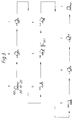
- FIG. 3 Various dispositions of a lead-acid battery 100 are shown in Figure 3 at points labelled A to J, which correspond to similarly labelled points in Figure 1.
- Lead-acid batteries travel through the battery acid dumping apparatus 10 in the direction X.
- the conveyor belts 18,20,22 move from the upstream roller 14 to the downstream roller 16 along their respective paths in substantially the direction X due the the drive means 36 acting on the upstream roller 14, and then return along the path which forms the fourth flat horizontal plane 58.
- the lead-acid battery 100 containing acid is guided by the guide means 24 to straddle the central conveyor belt 18 and the first outer conveyor belt 20 at point A.
- the first and second outer conveyor belts 20,22 rise at substantially the same angle causing the lead-acid battery 100 to tip through an angle of approximately 30 degrees as shown at point B.
- the curved side wall 70 may assist this tipping of the lead-acid battery 100.
- the first outer conveyor belt 20 continues to rise to the first station 42, but the second outer conveyor belt 22 drops causing the lead-acid battery 100 to tip over even further as shown at points C and D such that acid in the lead-acid battery 100 can start to drain out into the tank 12.
- the lead-acid battery will by now have preferably been tipped through an angle of anywhere between 120 and 180 degrees (preferably approximately 140 degrees), relative to its upright position.
- the lead-acid battery 100 remains at this angle between points E and F allowing substantially all the acid to drain from the lead-acid battery.
- the second outer conveyor belt 22 starts to rise, and at the second station 46, the first outer conveyor belt 20 begins to fall, such that the lead-acid battery 100 tips back as shown at point G.
- the curved side wall 72 assists the lead-acid battery to tip back to the position shown at point G.
- the second outer conveyor belt 22 continues to rise as the first outer conveyor belt 20 continues to fall, until the second outer conveyor belt reaches the sixth station 56, and the lead-acid battery 100 continues to tip back towards its upright position as shown at points H and I.
- the lead-acid battery 100 leaves the battery acid dumping apparatus 10 by way of output guide means 68. Whilst only one lead-acid battery 100 is shown, it will be appreciated that a number of lead-acid batteries may pass through the battery acid dumping apparatus 10 at any one time and on a continuous basis.
- each of the conveyor belts described above could comprise two or more belts.
- additional belts may be positioned between the central conveyor belt and the outer conveyor belts. Such changes can be made in order to alter the angle to which a battery is tipped and/or to change the speed of through-put.
- the battery acid dumping apparatus 10 of the present invention has several advantages over the previously known arrangements. It is very simple and clean, with little splashing of acid, and provides low maintenance costs. The acid can be easily collected for cleaning and recycling if desired. Lead-acid batteries can pass through the apparatus in a continuous line, without any stoppages for loading or unloading, thereby providing a continuous process, and a quick throughput. There is no need to make adjustments for batteries of varying sizes as the apparatus can handle mixed sizes of batteries. There is no need to provide sensors for detecting the presence of a lead-acid battery. The apparatus is cheap and can be run on an automatic basis with little or no surveillance. A single motor can be used to run the apparatus thereby providing low running costs.
Landscapes
- Chemical & Material Sciences (AREA)
- Chemical Kinetics & Catalysis (AREA)
- Electrochemistry (AREA)
- General Chemical & Material Sciences (AREA)
- Engineering & Computer Science (AREA)
- Mechanical Engineering (AREA)
- Secondary Cells (AREA)
- Processing Of Solid Wastes (AREA)
Applications Claiming Priority (2)
| Application Number | Priority Date | Filing Date | Title |
|---|---|---|---|
| GB9107656 | 1991-04-11 | ||
| GB9107656A GB2254727B (en) | 1991-04-11 | 1991-04-11 | Battery acid dumping apparatus |
Publications (3)
| Publication Number | Publication Date |
|---|---|
| EP0508512A2 true EP0508512A2 (de) | 1992-10-14 |
| EP0508512A3 EP0508512A3 (en) | 1993-03-10 |
| EP0508512B1 EP0508512B1 (de) | 1995-07-26 |
Family
ID=10693050
Family Applications (1)
| Application Number | Title | Priority Date | Filing Date |
|---|---|---|---|
| EP92200733A Expired - Lifetime EP0508512B1 (de) | 1991-04-11 | 1992-03-13 | Apparat zur Beseitigung von Batteriesäure |
Country Status (4)
| Country | Link |
|---|---|
| EP (1) | EP0508512B1 (de) |
| DE (1) | DE69203638T2 (de) |
| ES (1) | ES2074806T3 (de) |
| GB (1) | GB2254727B (de) |
Family Cites Families (8)
| Publication number | Priority date | Publication date | Assignee | Title |
|---|---|---|---|---|
| GB369447A (en) * | 1931-04-28 | 1932-03-24 | Giovanni Pastrone | Improvements relating to storage batteries |
| US2977007A (en) * | 1957-07-22 | 1961-03-28 | Morris P Kirk & Son Inc | Apparatus for dismantling electric storage batteries |
| US4203699A (en) * | 1976-03-22 | 1980-05-20 | General Battery Corporation | Method of dumping and collecting corrosive substances from _automotive batteries |
| US4081093A (en) * | 1976-03-22 | 1978-03-28 | General Battery Corporation | Apparatus for dumping and collecting corrosive substances from automotive batteries |
| US4225037A (en) * | 1978-04-07 | 1980-09-30 | General Battery Corporation | Acid-proof conveyor |
| US4294292A (en) * | 1979-11-01 | 1981-10-13 | General Battery Corporation | Tumble dumper |
| SE449348B (sv) * | 1984-05-08 | 1987-04-27 | Tetra Pak Int | Anordning vid transportor |
| US4685553A (en) * | 1985-11-21 | 1987-08-11 | Jennings Michael W | Container inverter |
-
1991
- 1991-04-11 GB GB9107656A patent/GB2254727B/en not_active Expired - Fee Related
-
1992
- 1992-03-13 ES ES92200733T patent/ES2074806T3/es not_active Expired - Lifetime
- 1992-03-13 EP EP92200733A patent/EP0508512B1/de not_active Expired - Lifetime
- 1992-03-13 DE DE69203638T patent/DE69203638T2/de not_active Expired - Fee Related
Also Published As
| Publication number | Publication date |
|---|---|
| GB2254727B (en) | 1994-07-20 |
| GB2254727A (en) | 1992-10-14 |
| GB9107656D0 (en) | 1991-05-29 |
| EP0508512A3 (en) | 1993-03-10 |
| DE69203638T2 (de) | 1996-01-11 |
| EP0508512B1 (de) | 1995-07-26 |
| ES2074806T3 (es) | 1995-09-16 |
| DE69203638D1 (de) | 1995-08-31 |
Similar Documents
| Publication | Publication Date | Title |
|---|---|---|
| US6503044B1 (en) | Method for emptying parcel containers | |
| CN205708649U (zh) | 一种自动收料机 | |
| CN110451293B (zh) | 卸货输送系统 | |
| EP0508512B1 (de) | Apparat zur Beseitigung von Batteriesäure | |
| CN206782166U (zh) | 一种自动化装盘机 | |
| CN115583384A (zh) | 条包水平理料机 | |
| CN209815219U (zh) | 卸货输送系统 | |
| CN112079135B (zh) | 用于搅拌站的物料输送控制方法和搅拌站 | |
| CN213084526U (zh) | 保温箱换冰系统及仓储系统 | |
| US3210833A (en) | Storage battery assembly machines | |
| CN220182142U (zh) | 一种料盘自动收投装置 | |
| CN112193284A (zh) | 一种可自动脱离的棒材运输装置 | |
| CN110369317A (zh) | 一种水力清洗水果分选装置 | |
| CN211329783U (zh) | 一种用于废旧电池带电破碎设备的自动给料装置 | |
| JP2755540B2 (ja) | 搬送容器反転設備 | |
| CN211544769U (zh) | 一种自动输料装置 | |
| JPH11278594A (ja) | 液体充填装置 | |
| CN114906637A (zh) | 一种袋式料装车装置及其使用方法 | |
| CN113083692A (zh) | 一种仓储物流中心自动化分拣处理系统及分拣处理方法 | |
| JP2544022B2 (ja) | 作物の選別用搬送装置 | |
| CN216613162U (zh) | 一种双向精准的物料装车系统 | |
| CN112249632A (zh) | 保温箱换冰系统及方法、仓储系统 | |
| EP0160280A2 (de) | Verfahren und Vorrichtung zum Zuführen von stabförmigen Gegenständen | |
| CN222683732U (zh) | 散装自动装车系统 | |
| US2122272A (en) | Battery dumper |
Legal Events
| Date | Code | Title | Description |
|---|---|---|---|
| PUAI | Public reference made under article 153(3) epc to a published international application that has entered the european phase |
Free format text: ORIGINAL CODE: 0009012 |
|
| AK | Designated contracting states |
Kind code of ref document: A2 Designated state(s): BE DE ES FR GR IT NL PT SE |
|
| PUAL | Search report despatched |
Free format text: ORIGINAL CODE: 0009013 |
|
| AK | Designated contracting states |
Kind code of ref document: A3 Designated state(s): BE DE ES FR GR IT NL PT SE |
|
| 17P | Request for examination filed |
Effective date: 19930504 |
|
| RAP1 | Party data changed (applicant data changed or rights of an application transferred) |
Owner name: ACG FRANCE |
|
| 17Q | First examination report despatched |
Effective date: 19941031 |
|
| GRAA | (expected) grant |
Free format text: ORIGINAL CODE: 0009210 |
|
| ITF | It: translation for a ep patent filed | ||
| AK | Designated contracting states |
Kind code of ref document: B1 Designated state(s): BE DE ES FR GR IT NL PT SE |
|
| PG25 | Lapsed in a contracting state [announced via postgrant information from national office to epo] |
Ref country code: GR Free format text: LAPSE BECAUSE OF FAILURE TO SUBMIT A TRANSLATION OF THE DESCRIPTION OR TO PAY THE FEE WITHIN THE PRESCRIBED TIME-LIMIT Effective date: 19950726 |
|
| RAP2 | Party data changed (patent owner data changed or rights of a patent transferred) |
Owner name: DELPHI FRANCE AUTOMOTIVE SYSTEMS |
|
| REF | Corresponds to: |
Ref document number: 69203638 Country of ref document: DE Date of ref document: 19950831 |
|
| ET | Fr: translation filed | ||
| REG | Reference to a national code |
Ref country code: ES Ref legal event code: FG2A Ref document number: 2074806 Country of ref document: ES Kind code of ref document: T3 |
|
| NLT2 | Nl: modifications (of names), taken from the european patent patent bulletin |
Owner name: DELPHI FRANCE AUTOMOTIVE SYSTEMS |
|
| PG25 | Lapsed in a contracting state [announced via postgrant information from national office to epo] |
Ref country code: PT Effective date: 19951026 |
|
| PLBE | No opposition filed within time limit |
Free format text: ORIGINAL CODE: 0009261 |
|
| STAA | Information on the status of an ep patent application or granted ep patent |
Free format text: STATUS: NO OPPOSITION FILED WITHIN TIME LIMIT |
|
| 26N | No opposition filed | ||
| NLXE | Nl: other communications concerning ep-patents (part 3 heading xe) |
Free format text: PAT.BUL.18/96 PAGE 3119:CORR.:DELPHI FRANCE AUTOMOTIVE SYSTEMS |
|
| REG | Reference to a national code |
Ref country code: FR Ref legal event code: CA |
|
| PGFP | Annual fee paid to national office [announced via postgrant information from national office to epo] |
Ref country code: SE Payment date: 20030311 Year of fee payment: 12 |
|
| PGFP | Annual fee paid to national office [announced via postgrant information from national office to epo] |
Ref country code: ES Payment date: 20030327 Year of fee payment: 12 |
|
| PGFP | Annual fee paid to national office [announced via postgrant information from national office to epo] |
Ref country code: BE Payment date: 20030328 Year of fee payment: 12 |
|
| PGFP | Annual fee paid to national office [announced via postgrant information from national office to epo] |
Ref country code: NL Payment date: 20030331 Year of fee payment: 12 |
|
| PG25 | Lapsed in a contracting state [announced via postgrant information from national office to epo] |
Ref country code: SE Free format text: LAPSE BECAUSE OF NON-PAYMENT OF DUE FEES Effective date: 20040314 |
|
| PG25 | Lapsed in a contracting state [announced via postgrant information from national office to epo] |
Ref country code: ES Free format text: LAPSE BECAUSE OF NON-PAYMENT OF DUE FEES Effective date: 20040315 |
|
| PG25 | Lapsed in a contracting state [announced via postgrant information from national office to epo] |
Ref country code: BE Free format text: LAPSE BECAUSE OF NON-PAYMENT OF DUE FEES Effective date: 20040331 |
|
| BERE | Be: lapsed |
Owner name: *ACG FRANCE Effective date: 20040331 |
|
| PG25 | Lapsed in a contracting state [announced via postgrant information from national office to epo] |
Ref country code: NL Free format text: LAPSE BECAUSE OF NON-PAYMENT OF DUE FEES Effective date: 20041001 |
|
| EUG | Se: european patent has lapsed | ||
| NLV4 | Nl: lapsed or anulled due to non-payment of the annual fee |
Effective date: 20041001 |
|
| PGFP | Annual fee paid to national office [announced via postgrant information from national office to epo] |
Ref country code: FR Payment date: 20050316 Year of fee payment: 14 |
|
| PGFP | Annual fee paid to national office [announced via postgrant information from national office to epo] |
Ref country code: DE Payment date: 20050530 Year of fee payment: 14 |
|
| REG | Reference to a national code |
Ref country code: ES Ref legal event code: FD2A Effective date: 20040315 |
|
| REG | Reference to a national code |
Ref country code: FR Ref legal event code: TP |
|
| PGFP | Annual fee paid to national office [announced via postgrant information from national office to epo] |
Ref country code: IT Payment date: 20060331 Year of fee payment: 15 |
|
| REG | Reference to a national code |
Ref country code: FR Ref legal event code: TP |
|
| PG25 | Lapsed in a contracting state [announced via postgrant information from national office to epo] |
Ref country code: DE Free format text: LAPSE BECAUSE OF NON-PAYMENT OF DUE FEES Effective date: 20061003 |
|
| REG | Reference to a national code |
Ref country code: FR Ref legal event code: ST Effective date: 20061130 |
|
| PG25 | Lapsed in a contracting state [announced via postgrant information from national office to epo] |
Ref country code: FR Free format text: LAPSE BECAUSE OF NON-PAYMENT OF DUE FEES Effective date: 20060331 |
|
| PG25 | Lapsed in a contracting state [announced via postgrant information from national office to epo] |
Ref country code: IT Free format text: LAPSE BECAUSE OF NON-PAYMENT OF DUE FEES Effective date: 20070313 |