EP0506305B1 - Siebdruckfähige Elektrolytzusammensetzung, miniaturisierte Sauerstoffelektrode, und Verfahren zur Herstellung derselben - Google Patents
Siebdruckfähige Elektrolytzusammensetzung, miniaturisierte Sauerstoffelektrode, und Verfahren zur Herstellung derselben Download PDFInfo
- Publication number
- EP0506305B1 EP0506305B1 EP92302399A EP92302399A EP0506305B1 EP 0506305 B1 EP0506305 B1 EP 0506305B1 EP 92302399 A EP92302399 A EP 92302399A EP 92302399 A EP92302399 A EP 92302399A EP 0506305 B1 EP0506305 B1 EP 0506305B1
- Authority
- EP
- European Patent Office
- Prior art keywords
- electrolyte
- substrate
- oxygen
- containing material
- permeable membrane
- Prior art date
- Legal status (The legal status is an assumption and is not a legal conclusion. Google has not performed a legal analysis and makes no representation as to the accuracy of the status listed.)
- Expired - Lifetime
Links
Images











Classifications
-
- G—PHYSICS
- G01—MEASURING; TESTING
- G01N—INVESTIGATING OR ANALYSING MATERIALS BY DETERMINING THEIR CHEMICAL OR PHYSICAL PROPERTIES
- G01N27/00—Investigating or analysing materials by the use of electric, electrochemical, or magnetic means
- G01N27/26—Investigating or analysing materials by the use of electric, electrochemical, or magnetic means by investigating electrochemical variables; by using electrolysis or electrophoresis
- G01N27/403—Cells and electrode assemblies
- G01N27/404—Cells with anode, cathode and cell electrolyte on the same side of a permeable membrane which separates them from the sample fluid, e.g. Clark-type oxygen sensors
Definitions
- the present invention relates to a diaphragm-type miniaturized oxygen electrode, more particularly, to a miniaturized oxygen electrode useful for many applications including the measurement of the dissolved oxygen concentration of a solution; to an electrolyte composition suitable for forming the sensing site of the miniaturized oxygen electrode ; and to a process of mass-producing miniaturized oxygen electrodes having a uniform quality.
- An oxygen electrode is very useful for measuring the dissolved oxygen concentration in many fields.
- oxygen electrodes are used in the field of water control, where the BOD (Biochemical Oxygen Demand) in water is measured.
- BOD Biochemical Oxygen Demand
- the dissolved oxygen concentration of a fermentation tank or fermenter is measured to ensure an efficient fermentation of alcohol, etc.
- An oxygen electrode can be combined with an enzyme to form a biosensor or an enzyme electrode to be used for measuring the concentration of sugar, vitamins, etc.
- an oxygen electrode can be combined with glucose oxidase to measure the concentration of glucose or grape sugar.
- This biosensor utilizes the catalytic action of glucose oxidase in promoting the oxidation of glucose by the dissolved oxygen to form gluconolactone, with a resulting reduction in the amount of dissolved oxygen diffusing into the oxygen electrode.
- an oxygen electrode can be advantageously used in the control of the oxygen concentration of a gas phase.
- a reduction in the ambient oxygen concentration to below 18% causes a dangerous oxygen deficiency.
- the oxygen concentration of a gas used must be strictly controlled.
- the oxygen electrode thus finds advantageous use in many fields, including environmental instrumentation, the fermentation industry, clinical care, and industrial hygiene.
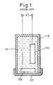
- the conventional oxygen electrode typically has the structure as shown in Fig. 1.
- a vessel or container 118 made of glass, plastics, stainless steel, or the like has an open end (lower end) covered and sealed with an oxygen gas-permeable membrane 107 made of silicone resin, fluororesin or the like.
- the vessel 118 is filled with an aqueous solution 119 of potassium chloride (KC1), sodium hydroxide (NaOH), etc., and an anode 104 made of silver (Ag), lead (Pb), etc., and a cathode 105 made of platinum (Pt), gold (Au), etc., are arranged.
- KC1 potassium chloride
- NaOH sodium hydroxide
- anode 104 made of silver (Ag), lead (Pb), etc.
- a cathode 105 made of platinum (Pt), gold (Au), etc.
- the conventional oxygen electrode has a complicated structure, and therefore, it is difficult to miniaturize and also to mass-produce.
- the present inventors and others have proposed a new type of miniaturized oxygen electrode that can be produced by utilizing a semiconductor production process including photolithography and anisotropic etching, as disclosed in Japanese Unexamined Patent Publication (Kokai) No. 63-238,548 and US-A- 4,975,175.
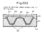
- the new type of oxygen electrode has the structure shown in Fig . 2 in which Fig. 2(b) shows an unfinished structure with an oxygen gas-permeable membrane not yet having been formed.
- This structure is produced by the following sequence. Two grooves 202 to be filled with an electrolyte-containing material are formed on a silicon wafer 201 by anisotropic etching. The wafer surface is then covered by an SiO 2 insulating layer 203 to form an electrically insulating substrate. Then, two component electrodes, i.e., an anode 204 and a cathode 205, are formed on the insulating layer 203.
- One end 204A of the anode 204 is for external electrical connection and the other end has a branch extending into each of the grooves 202.
- One end 205A of the cathode 205 is for external electrical connection and the other end extends to the top surface of a plateau between the grooves 202.
- the grooves 202 are filled with an electrolyte-containing material 206, such that the electrolyte-containing material 206 is in contact with the anode 204 within the grooves 202 and with the cathode 205 on the plateau.
- the upper surface of the electrolyte-containing material 206 is then covered with an oxygen gas-permeable membrane 207.
- the step of filling the grooves 202 with the electrolyte-containing material 206 and the step of covering the electrolyte-containing material 206 with the oxygen gas-permeable membrane 207 are difficult to carry out in a semiconductor process. Therefore, they are carried out manually chip by chip after the wafer 201 on which miniaturized oxygen electrodes have been formed is cut into chips forming respective oxygen electrodes.
- the manual operation is a serious obstacle to the realizing mass-production and, furthermore, involves too much fluctuation in operation to obtain miniaturized oxygen electrodes having a stable or uniform performance.
- the step of filling the electrolyte-containing material has the following problems.
- the present inventors studied gels containing an aqueous solution of potassium chloride and polyelectrolytes and found that, because many of these are not photosensitive, the photolithography used in the semiconductor process cannot be actually applied to the filling of an electrolyte-containing material.
- the electrolyte-containing material must be a liquid having a fluidity when it is filled in a groove, and the filled material must form a dense film after being dried. Also, whether or not the filled material contains water significantly affects the quality of the oxygen gas-permeable membrane applied on the filled material. Therefore, upon application of an oxygen gas-permeable membrane, the electrolyte-containing material is preferably dried.
- the water required for the measurement of the oxygen concentration is supplied as a water vapor through the gas-permeable membrane just before the measurement starts.
- the electrolyte-containing material need not contain water during the production of an oxygen electrode.
- Screen printinq is a preferred method of filling collectively a number of miniaturized oxygen electrodes on a wafer with an electrolyte-containing material.
- This screen printing generally uses an emulsion mask or a metal mask to define a printed pattern.
- the emulsion mask is prepared by applying a photosensitive resin in the form of an emulsion on a mesh of stainless steel, etc. to provide a printing pattern.
- Some resins have a transparency which advantageously facilitates the fine alignment required when producing a miniaturized oxygen electrode because a wafer covered by a resin mask is visible through the resin.
- the emulsion mask is very weak against water, as can be understood from the fact that the developing treatment of an emulsion is carried out by using water, and the printing of a water-containing substance is difficult.
- the metal mask is prepared by forming holes in a plate of a stainless steel, etc., and therefore, is strong against water.
- the metal mask is disadvantageous from the point of view of the fine alignment, because it is not transparent.
- the metal mask occasionally provides a printing quality lower than that obtained by the emulsion mask, when using some kinds of printing inks.
- the present inventors proposed a process in which an electrolyte-containing gel is applied by screen printing, i.e. calcium alginate gel, polyacrylamide gel, and agarose gel, as disclosed in Japanese Unexamined Patent Publication (Kokai) No. 1-56,902.
- This process uses a metal mask to print an aqueous gel and cannot be advantageously used in the production of a miniaturized oxygen electrode, for the reasons mentioned above.
- a strong film cannot be obtained because the oxygen gas-permeable membrane is formed on a wet gel.
- Potassium chloride is generally used as the electrolyte of an oxygen electrode.
- potassium chloride is a superior electrolyte, it is not suitable for use in a miniaturized oxygen electrode because it has a drawback in that it is only soluble in water and that a filled aqueous solution thereof becomes a white brittle powder when dried.
- the present inventors also proposed a polyelectrolyte, as disclosed in Japanese Unexamined Patent Publication (Kokai) No. 2-240,556. Although this has a good film forming property, the proposed polyelectrolyte is also soluble only in water, and is difficult to treat because it has a high polymerization degree and exhibits a high viscosity even as a dilute solution.
- the step of forming an oxygen gas-permeable membrane has the following problems.
- the gas-permeable membrane is made of silicone resin, fluororesin, or other electrically insulating material.
- the gas-permeable membrane is therefore formed not to cover the whole surface of a wafer, but to have a pattern such that the component electrode ends or "pads" 204A and 205 for external electrical connection are exposed.
- the gas-permeable membrane is formed selectively in the predetermined region of the wafer other than the pad region which is to be exposed, either by applying a resin only to the predetermined region or by first forming the gas-permeable membrane on the whole surface of the wafer and then removing the gas-permeable membrane in the pad region to be exposed.
- the former method i.e., the selective application of a resin
- This method has an advantage in that a single printing operation simultaneously effects both the application and the patterning of the resin.
- the silicone resin used for forming the gas-permeable membrane is progressively cured by water in the ambient air. Therefore, the viscosity of the resin varies during printing, causing nonuniform printing and, in the worst case, clogging of the printing stencil.
- U.S. Patent No. 4,062,750 to J.F. Butler discloses a thin film type electrochemical electrode formed on a silicon substrate, having a feature that an electroconductive layer extends through the silicon substrate thickness so that a signal from a sensor disposed on one side of the substrate is taken out from the other side of the substrate.
- a gas-permeable membrane may cover the whole surface and patterning of the membrane for exposing the pad portion is not required.
- This electrode requires a complicated production process, causinq a problem in the practical application thereof.
- the filling of an electrolyte is carried out by vacuum deposition, and although sodium chloride and potassium chloride can be vacuum deposited, many of the inorganic salts used as a buffering agent are deteriorated by dehydration and condensation when exposed to the heat associated with vacuum deposition. Therefore, even when a buffered electrolyte is obtained, the resulting pH will significantly deviate from an expected value and the obtained electrolyte composition must be very restricted. Thus, this is not an optimum process. Moreover, a problem arises when a single vacuum desposition apparatus is used for depositing both electrolytes and electrode metals, Therefore, individual deposition apparatuses must be provided for the respective depositions.
- M.J. Madou et al. proposed a micro-electrochemical sensor, as disclosed in U.S. Patent No. 4,874,500 and in AIChE SYMPOSIUM SERIES, No. 267, vol. 85, pp. 7-13 (1989).
- This sensor also has a feature in that an electroconductive layer extends through the silicon substrate thickness and a signal from a sensor disposed on one side of the substrate is taken out from the other side of the substrate. Therefore, it has the same drawback as that of US-A-4062750.
- An electrolyte is filled in such a manner that an alcoholic solution of poly(hydroxyethylmethacrylate), etc.
- the electrolyte solution is introduced to form a gel, and is then dried.
- the conventional problem is apparently eliminated, because the electrolyte is introduced after a polymer is applied, but a crystal grows when a potassium chloride solution is evaporated.
- the amount of potassium chloride is small, the grown crystal is enclosed by the polymer, but when the amount is large, a number of large crystals appear, which may not be supported by the polymer.
- the amount of electrolyte must be as large as possible, because the service life of an oxygen electrode is affected by the electrolyte amount contained therein. Thus, the restricted amount of electrolyte reduces the service life of the oxygen electrode.
- An object of the present invention is to provide a miniaturized oxygen electrode which can be mass-produced at a high efficiency by collectively and uniformly processing a substrate as a whole, a production process therefor, and an electrolyte composition able to be advantageously used therein.
- an electrolyte composition for screen printing comprising:
- the electrolyte composition is suitable for screen-printing to form an electrolyte-containing material on a substrate.
- the inorganic salt is preferably potassium chloride or sodium chloride.
- the inorganic salt used as the electrolyte must be in the form of a fine powder which can pass through the screen printing mesh, for example, in the form of a fine particle having a diameter not larger than 50 ⁇ m.
- the organic solvent used in the present invention is preferably an alcohol such as butanol, pentanol, or hexanol.
- the electrolyte composition of the first aspect of the present invention is prepared by dispersing an inorganic salt such as potassium chloride, which is a superior electrolyte, in the form of fine particles adapted for screen printing, in a high molecule polymer dissolved in an organic solvent.
- the present invention uses polyvinyl pyrrolidone as the high molecule polymer.
- An inorganic salt, such as potassium chloride, in the form of fine particles may be prepared either by pulverizing a solid material or by pouring a saturated or near-saturated aqueous solution of the inorganic salt into an organic solvent such as alcohol and acetone, which can be mixed with water in any proportion, to precipitate fine particles. Either method provides a powder of fine particles having a uniform size.
- the electrolyte composition may further comprise a buffering agent, to ensure a constant pH (hydrogen ion concentration) of the electroylyte.
- the buffering agent is preferably a salt exhibiting a buffering effect, such as phosphate, acetate, borate, citrate, phthalate, tetraborate, glycine salt, and tris (hydroxymethyl)-aminomethane salt, and is preferably used in the form of a fine powder like the potassium chloride powder.
- a miniaturized oxygen electrode comprising:
- a process for producing a miniaturized oxygen electrode comprising:
- a fine powder of an inorganic salt, polyvinyl pyrrolidone, and an organic solvent are blended to form an electrolyte composition in the form of a paste, which is then applied to a substrate at predetermined portions collectively by screen printing.
- the printed electrolyte composition when dried, forms a dense film such that an oxygen gas-permeable membrane can be properly formed thereon.
- the oxygen gas-permeable membrane may be formed by:
- the removable cover film may be formed by screen-printing a thermosetting resin onto said region of said substrate including the ends of the component electrodes for external electrical connection, and curing said resin by heating.
- the oxygen gas-permeable membrane is formed selectively or patterned to cover the necessary region of the substrate surface by first covering a region of substrate to be exposed with a removable cover film, applying a resin for forming an oxygen gas-permeable membrane onto the whole surface of the substrate by spin coating, and then peeling or exfoliating the removable cover film, thereby to remove the oxygen gas-permeable membrane together with the cover film in the region of substrate to be exposed.
- the present invention uses, as the material of the removable cover film, a thermosetting resin, a solution of polyvinylchloride in an organic solvent, or other resins. Such resins are preferably applied to the predetermined region of a substrate by screen printing, and then cured by heating or drying to form a removable cover film.
- the electrically insulating substrate of the miniaturized oxygen electrode may be an electrically insulating substrate having a flatness and a smoothness sufficient for forming a miniaturized oxygen electrode by using the semiconductor process.
- a silicon wafer is most advantageously used as the insulating substrate, from the viewpoint of the application of the production process of silicon semiconductors currently most generally used.
- the present invention may be directly applied to miniaturized oxygen electrodes formed on insulating substrates other than the silicon wafer.
- a miniaturized oxygen electrode may be produced by using a flat substrate of an electrically insulating substance such as glass, quartz and plastics, in such a manner that a component electrode pattern is formed on the substrate, an electrolyte-containing material is filled in the oxygen sensing site by screen printing an electrolyte composition in accordance with first aspect of the present invention, and then an oxygen gas-permeable membrane is selectively formed or patterned by steps including forming a removable cover film by screen-printing a thermosetting resin, etc., on the pad portion, i.e., the region of the substrate including ends of the component electrodes for external electrical connection.
- the present invention also provides an advantage in that a number of miniaturized oxygen electrodes are formed collectively at one time on the whole region of an integral substrate.
- the screen-printed electrolyte composition contains a fine powder of an inorganic salt or an electrolyte not dissolved but dispersed in an organic solvent. Therefore, the inorganic salt, even when dried, does not form a brittle crystal but remains a fine powder, and this enables an electrolyte-containing material in the form of a dense solid material to be formed.
- the thus obtained electrolyte-containing material is essentially composed of the inorganic salt and polyvinyl pyrrolidone. Upon operating a miniaturized oxygen electrode including such an electrolyte-containing material, water is introduced into the electrolyte-containing material.
- Both the inorganic salt and polyvinyl pyrrolidone are water-soluble and completely dissolved in the introduced water.
- the electrolyte-containing material satisfies the requirement for a miniaturized oxygen electrode that it remains in a solid state during the formation of an oxygen gas-permeable membrane and forms an aqueous solution when the miniaturized oxygen electrode is operated.
- Potassium chloride and sodium chloride are superior electrolytes and can be advantageously used as the inorganic salt according to the present invention, to obtain the best performance of a miniaturized oxygen electrode.
- a salt having a pH buffering effect such as phosphate
- the electrolyte composition ensures that the electrolyte has a constant pH.
- the electrochemical reaction in the oxygen electrode depends on the pH value, the constant pH improves the stability of the performance of the oxygen electrode.
- the miniaturized oxygen electrode according to the present invention is produced by filling an electrolyte composition,containing an inorganic salt as an electrolyte in the form of a fine powder, collectively in all of the predetermined portions of a substrate, by screen printing,thereby to ensure a uniform filling operation and a high productivity.
- an electrolyte composition containing an inorganic salt as an electrolyte in the form of a fine powder is filled collectively in all of the predetermined portions of a substrate by screen printing. This ensures a uniform filling operation and mass-production of a miniaturized oxygen electrode, even when the portion to be filled has a complicated shape.
- the production process can also advantageously cope with any increase in the number of filling portions associated with an enlargement of the substrate size.
- a high productivity is ensured even when the oxygen gas-permeable membrane and the exposed portion have a complicated shape. This is because the oxygen gas-permeable membrane is patterned (or selectively formed) by removing a cover film formed in a predetermined shape.
- the oxygen gas-permeable membrane is applied on the entire substrate surface, preferably by spin-coating, and thereby a high productivity is ensured and an oxygen gas-permeable membrane having a uniform thickness over the entire substrate surface is formed.
- the oxygen gas-permeable membrane is preferably selectively formed by first covering a substrate region to be exposed with a removable cover film, forming an oxygen gas-permeable membrane collectively on the entire substrate surface, and then peeling or exfoliating the removable cover film.
- the oxygen gas-permeable membrane may be patterned by the steps of: applying a thermosetting resin of a resin dissolved in an organic solvent to the to-be-exposed portions by screen printing; curing the applied resin by heating or drying to form a removable cover film; and then peeling or exfoliating the removable cover film.
- a process sequence for producing a miniaturized oxygen electrode according to the present invention using a silicon wafer will be described below. Although, for simplicity the sequence is described for the case in which a miniaturized oxygen electrode is formed on a 2-inch silicon wafer, essentially the same process sequence can be used for a larger wafer.
- Step 1 Cleaning Wafer
- a 2-inch silicon wafer 301 (400 ⁇ m thick, (100) plane) was thoroughly cleaned with a mixed solution of hydrogen peroxide and ammonia and with concentrated nitric acid.
- Step 2 Forming SiO 2 Layer (Fig. 3(a))
- the wafer 301 was wet-thermally oxidized at 1000°C for 200 min. to form a 0.8 ⁇ m thick SiO 2 layer 312 on both sides of the wafer.
- the SiO 2 layer 312 is to be patterned in the following step 4 and used as a mask when anisotropically etching the silicon wafer in the following step 5.
- Step 3 Forming Resist Pattern (Fig. 3(b))
- a negative-type photoresist (Tokyo Ohka Kogyo Co., Ltd., OMR-83, viscosity 60cP) was applied on the entire upper surface of the wafer, prebaked at 80°C for 30 min. and was subjected to a photolithography treatment to form a resist pattern 313.
- the resist pattern 313 covers the upper surface of the wafer 301 except for a region 302A at which grooves 302 (Fig. 3(d)) for receiving an electrolyte-containing material are to be formed in the following step 5.
- the resist pattern 313 serves as a mask upon etching the SiO 2 layer 312 in the following step 4.
- the same photoresist was applied on the lower surface of the wafer 301, which was then baked at 150°C for 30 min.
- the wafer 301 was immersed in an etchant for SiO 2 (50%HF/lml + NH 4 F/6 ml) to remove the SiO 2 layer 312 in the portion 302A not covered with the photoresist 313.
- the wafer 301 was then immersed in a mixed solution of concentrated sulfuric acid and hydrogen peroxide, to remove the photoresist 313.
- Step 5 Anisotropically Etching Silicon Wafer (Fig. 3(d))
- the wafer 301 was immersed in an etchant for silicon (35% KOH) at 80°C to anisotropically etch the silicon wafer 301 by using the SiO 2 layer as a mask, thereby forming two 300 ⁇ m deep grooves 302 for receiving an electrolyte-containing material. After the anisotropic etching was finished, the wafer 301 was cleaned with pure water.
- an etchant for silicon 35% KOH
- Step 6 Removing SiO 2 Layer (Fig. 3(e))
- the SiO 2 layer 312 was removed by the same operation as that performed in Step 4.
- Step 7 Forming SiO 2 Layer (Fig. 3(f))
- Steps 1 and 2 The same operations as performed in Steps 1 and 2 were carried out to effect a thermal oxidation of the wafer 301, and thereby form a 0.8 ⁇ m thick SiO 2 layer 303 on the entirety of both sides of the wafer 301.
- the thus-formed SiO 2 layer 303 functions as an insulating layer of a miniaturized oxygen electrode or the final product.
- Step 8 Forming Thin Layers of Chromium and Silver (Figs. 3(g1), 3(g2))
- the silver layer 315 is an electroconductive layer composing the substantial portion of component electrodes (anode and cathode) and the chromium layer 314 is a ground layer for ensuring adhesion of the silver layer 315 to the SiO 2 insulating layer 303 formed on the wafer 301.
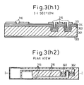
- Step 9 Forming Photoresist Pattern (Figs. 3(h1), 3(h2))
- This step provides a photoresist pattern 316 to be used as a mask in the following Steps 10 and 11, in which the silver layer 315 and the chromium layer 314 are etched to thereby effect a patterning of component electrodes (anode and cathode) of the miniaturized oxygen electrode.
- a positive-type photoresist (Tokyo Ohka Kogyo Co., Ltd., OFPR-800, viscosity 20 cP or OFPR-5000, viscosity 50 cP) was dropped on the wafer 301 to uniformly cover the wafer 301.
- the photoresist is preferably dropped in an amount such that it spreads just to the circumferential edge of the wafer.
- the wafer 301 was prebaked at 80°C for 30 min.
- the wafer 301 was pattern-aligned with a glass mask by a mask aligner, exposed to light, and developed to form a photoresist pattern 316. The exposure and development cycle was repeated to ensure a complete exposure of the positive-type photoresist layer, which is too thick to complete the exposure over the thickness in one step.
- Step 10 Etching Thin Layers of Silver and Chromium (Figs. 3(i1) and 3(i2))
- the wafer 301 was immersed in an etchant for silver (NH 3 water/1 ml + H 2 O 2 /1 ml + water/20 ml) to remove the bare portion of the silver layer, and thereby form the substantial portion of the component electrodes.
- an etchant for silver NH 3 water/1 ml + H 2 O 2 /1 ml + water/20 ml
- the wafer was then immersed in an etchant for chromium (NaOH/0.5 g + K 3 Fe(CN) 6 /1 g + water/4 ml) to remove the bare portion of the chronium layer 314.
- Step 11 Forming Photoresist Pattern (Fig. 3(j1) and 3(j2)
- This step provides a photoresist pattern 317 for defining the oxygen sensing site of the miniaturized oxygen electrode.
- a layer 317 of a negative-type photoresist (Tokyo Ohka Kogyo Co., Ltd., OMR-83, viscosity 60 cP) was formed on the wafer 301 to cover the wafer surface except for the region 309 of the oxygen sensing site (two grooves and a flat plateau therebetween) and a pad region 311, at which the pad portions 304A and 305A of component electrodes 304 and 305 are to be formed. This is performed by applying the photoresist to the wafer surface, prebaking the wafer at 80°C for 30 min, and exposing to light and developing the photoresist layer. Thereafter, the photoresist layer was postbaked at 150°C for 30 min.
- a negative-type photoresist Tokyo Ohka Kogyo Co., Ltd., OMR-83, viscosity 60 cP
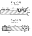
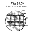
- Step 12 Screen-Printing Electrolyte Composition (Figs. 3(k1), 3(k2) and 3(k3))
- An electrolyte composition was screen-printed at the oxygen sensing site 309 (two grooves and the flat plateau therebetween) defined by the photoresist 317, to form an electrolyte-containing material 306.
- the preparation of the electrolyte used will be described later.
- Step 13 Forming Pad Region Cover Film (Figs. 3(l1) and 3(l2))
- thermosetting release coating (Fujikura Kasei Co. XB-801) was screen-printedon the pad region 311 at a thickness of 100 ⁇ m and cured by heating at 150°C for 10 min. to form a removable cover film 308.
- Step 14 Forming Oxygen Gas-Permeable Membrane (Figs. 3(m1) and 3(m2))
- An oxygen gas-permeable membrane 307 having a double-layered structure was formed on the wafer 301 to entirely cover the upper surface of the wafer 301.
- the lower layer of the membrane 307 was first formed by applying a negative-type photoresist (Tokyo Ohka Kogyo Co., Ltd., OMR-83, viscosity 100 cP) to the wafer 301 by spin coating, prebaking at 80°C for 30 min., exposing the entire wafer surface to light and developing, and postbaking at 150°C for 30 min.
- the upper layer of the membrane 307 was then formed by applying a silicone resin (Toray-Dow Corning Silicone Co. SE9176) to the wafer 301 by spin coating and curing the coated resin by heating at 70°C for 30 min. in an oven moistened by water contained in a Petri dish or a beaker placed in the oven.
- Step 15 Exposing Pads (Figs. 3(n1) and 3(n2)
- the cover film 308 formed on the pad region 311 was peeled with a pincette to-selectively remove the oxygen gas-permeable membrane in that region, and thereby expose the pads 304A and 305A of a miniaturized oxygen electrode.
- Step 16 Separating Miniaturized Oxygen Electrodes
- a number of miniaturized oxygen electrodes were collectively formed on the wafer 301 at one time by the preceding Steps 1 to 15 and were cut into chips by a dicing saw.
- the shown example provides forty chips with miniaturized oxygen electrodes at one time.
- Step 13 of forming a pad region cover film was modified as follows:
- Step 13' Forming Pad Region Cover Film (Modified)
- Polyvinylchloride resin dissolved in tetrahydrofuran was screen-printed on the pad region 311 at a thickness of 50 ⁇ m and cured by heating at 70°C to form a cover film 308.
- the electrolyte composition according to the present invention used in Step 12 of Examples 1 and 2 was prepared in the following manner.
- Fine particles of potassium chloride or sodium chloride were formed by either of the following procedures (a) or (b):
- Electrolyte Composition Case 1 Potassium chloride fine particles 0.25 g Polyvinyl pyrrolidone 1 g Pentanol 5 g
- Electrolyte Composition Case 2 Potassium chloride fine particles 4 g Polyvinyl pyrrolidone 1 g Pentanol 5 g
- the electrolyte composition further comprises a salt having a pH-buffering effect.
- a phosphate was added in the following case, the buffering agent used in the present invention may be selected from the group consisting of phosphates, accetates, borates, citrates, phthalates, tetraborates, glycine salts, and tris(hydroxymethyl)aminomethane salts.
- An electrolyte composition with the addition of a phosphate as a buffering agent may be prepared in the following manner, for example.
- Fine particles of potassium chloride or sodium chloride were formed by either of the following procedures (a)or (b):
- the fine particles of potassium chloride or sodium chloride and the fine particles of phosphate or a buffering agent may be prepared separately.
- a concentrated aqueous solution of potassium chloride or sodium chloride is formed, an aqueous solution of potassium dihydrogen phosphate and sodium dihydrogen phosphate (4 : 6 in molar ratio) can be separately formed. Both solutions are preferably in a saturation state, which provides a greater amount of fine particles, i.e., a high efficiency.
- the weighed phosphates must be completely dissolved in water, because the proportion of the dissolved phosphates significantly affects the pH value.
- the thus-prepared aqueous solutions are poured into an organic solvent such as ethanol, in the same manner as described above, and the precipitated fine particles are collected.
- Electrolyte Composition Case 3 Mixture of fine particles of potassium chloride and phosphate 0.25 g Polyvinyl pyrrolidone 1 g Pentanol 5 g Electrolyte Composition: Case 4 (fine particles of buffering agent separately formed) Potassium chloride fine particle 3.5 g Phosphate fine particle 0.5 g Polyvinyl pyrrolidone 1 g Pentanol 5 g
- the performance of the miniaturized oxygen electrode produced in Examples 1 and 2 was tested by measuring the dissolved oxygen concentration of a 10 mM buffered phosphoric acid solution having a pH value of 7.0 at an applied voltage of 0.6 V and a temperature of 25°C.
- Figure 4 shows a response curve observed when sodium sulfite is added to a solution saturated with 100% oxygen, to instantaneously reduce the oxygen concentration to zero.
- the response time was 40 seconds, which corresponded to the variation of the dissolved oxygen concentration.
- Figure 5 shows a calibration curve obtained in this case, from which it is seen that a good linearity is ensured over the entire range of the dissolved oxygen concentration of from 0 ppm through 8 ppm, i.e., the saturation concentration.
- FIG. 6 a process sequence for producing a miniaturized oxygen electrode according to the present invention by using an electrically insulating flat substrate other than a silicon wafer will be described.
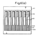
- Step 1 Forming Component Electrode Pattern (Fig. 6(a))
- the insulating substrate 401 may be made of glass, quartz, ceramics, plastics or other electrically insulating substances.
- a component electrode pattern consisting of an anode 404 and a cathode 405 was formed on the insulating substrate 401 by either of the following procedures (a) or (b):
- the component electrodes 404 and 405 have ends for external electrical connections or pads 404A and 405A, respectively.
- An auxiliary pad 420 provided between the pads 404A and 405A can be used for a miniaturized oxygen electrode having a three-pole structure, for example.
- Step 2 Screen-Printing Electrolyte Composition (Fig. 6(b))
- Example 2 The same electrolyte composition as used in Example 1 was screen-printed to fill the region 409 of the oxygen sensing site, and thereby form an electrolyte-containing material 406.
- Step 3 Forming Pad Region Cover Film (Fig. 6(c))
- thermosetting release coating (Fujikura Kasei Co., XB-801) was screen-printed at the region 411 of the pad containing the pads 404A and 405A and the auxiliary pad 420, to form a cover film 408 covering the pad region 411.
- Step 4 Forming Oxygen Gas-Permeable Membrane (Fig. 6(d))
- An oxygen gas-permeable membrane 407 having a double-layered structure was formed on the substrate 401 to entirely cover the upper surface of the substrate 401.
- the lower and the upper layers of the membrane 407 were formed by applying a negative-type photoresist (Tokyo Ohka Kogyo Co., Ltd., OMR-83, viscosity 100 cP) and a silicone resin (Toray-Dow Corning Silicone Co., SE9176) by spin coating, respectively, and then curing the applied layers.
- Step 5 Exposing Pad Region (Fig. 6(e))
- the cover film 408 formed on the pad region 411 was peeled with a pincette to selectively remove the oxygen gas-permeable membrane 407fromthat portion, and thereby expose the pads 404A and 405A of a miniaturized oxygen electrode.
- the auxiliary pad 420 was simultaneously exposed.
- Step 6 Separating Miniaturized Oxygen Electrodes (Fig. 6(f))
- a plurality of miniaturized oxygen electrodes were collectively formed on the electrically insulating substrate 401 by the preceding Steps 1 to 6, and were cut into chips by a dicinq saw.
- the illustrated example simultaneously provided seven chips of miniaturized oxygen electrodes 418 from a single substrate .
- the component electrodes may be formed of gold instead of silver, or a cathode and an anode may be formed of gold and silver, respectively.
- the component electrodes can be formed of gold instead of silver by a partial modification of the process steps of Example 1, as follows.
- Steps 8 and 10 of Example 1 were modified in the following manner.
- Step 8 the same operation was performed as in Example 1, except that a gold layer 315 (4000 ⁇ thick) was vacuum deposited instead of the silver layer 315 (4000 ⁇ thick).
- Step 10 the same operation was performed as that in Example 1, except that the wafer 301 was immersed in an etchant for gold (KI/4 g + I 2 /1 g + water/40 ml) instead of the etchant for silver.
- an etchant for gold KI/4 g + I 2 /1 g + water/40 ml
- a miniaturized oxygen electrode having a gold cathode and a silver anode may be produced in the following manner.
- a process sequence for producing a miniaturized oxygen electrode having a gold cathode and a silver anode according to the present invention using a glass substrate will be described.
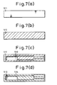
- Step 1 Cleaning Substrate (Fig. 7(a))
- a 60 mm square, 1.6 mm thick glass substrate 511 was thoroughly washed with a detergent (for example, Furuuchi Kagaku Co., Semico Clean 56) and acetone.
- a detergent for example, Furuuchi Kagaku Co., Semico Clean 56
- acetone for example,
- Step 2 Forming Thin Layers of Chromium, Gold and Silver (Fig. 7(b))
- a chromium layer 400 ⁇ thick, for example
- a gold layer (4000 ⁇ , for example)
- a silver thin layer 512 (4000 ⁇ thick, for example) were formed on the substrate 511, in that order, by vacuum deposition.
- the chronium layer ensures a good adhesion between the glass substrate 511 and component electrodes of gold and silver.
- Step 3 Forming Photoresist Pattern (Fig. 7(c))
- a positive-type photoresist (for example, Tokyo Ohka Kogyo Co., Ltd., OFPR-800, 20 cP or OFPR-5000, 50 cP) was applied on the silver layer 512 and prebaked at 80°C for 30 min. The thus-formed photoresist layer was exposed to light and developed to form a photoresist pattern 513 corresponding to all component electrodes.
- the substrate 511 was immersed in an etchant for silver (for example, 29%NH 4 OH/1 ml + 31%H 2 O 2 /1 ml + water/20 ml) to pattern the silver layer 512.
- the substrate 511 was then immersed in an etchant for gold (for example, KI/4 g + I 2 /1 g + water/40 ml) to pattern the gold layer.
- Step 5 Re-Patterning Photoresist Pattern (Fig. 7(e))
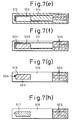
- the positive-type photoresist layer 513 was exposed to light and developed again so that the photoresist pattern 513 remained only in the portion at which an anode is to be formed, and the other portion of the photoresist pattern 513 was removed to expose the silver layer 512.
- the substrate 511 was immersed in an etchant for silver to remove the silver layer exposed in the preceding Step 5, and thereby expose the underlying gold layer, with the result that the gold cathode 504, including part of the extended card edge portion (or pad) 503, and part of a floating card edge portion (or pad), were exposed.
- the substrate was then immersed in an etchant for chromium (for example, NaOH/0.5 g + K 3 Fe(CN) 6 /1 g + water/4 ml) to remove the open portion of the chromium layer 514.
- the substrate was immersed in acetone to entirely remove the photoresist pattern 513, and thereby expose the silver anode 505 including part of the extended card edge portion (or pad) 503.
- Step 7 Forming Photoresist Pattern (Fig. 7(g))
- a negative-type photoresist (for example, Tokyo Ohka Kogyo Co., Ltd., OMR-83, 60 cP) was applied to the entire upper surface of the substrate 511 by spin coating and prebaked at 70-80°C for 30 min. After an exposure to light and development, the photoresist was postbaked at 150°C for 30 min. to form a photoresist pattern 516, which covered the substrate surface except for the oxygen sensing site 515 of the silver anode 505, part of the gold cathode 504, and the card edge portion (or pad) 503.
- a photoresist pattern 516 which covered the substrate surface except for the oxygen sensing site 515 of the silver anode 505, part of the gold cathode 504, and the card edge portion (or pad) 503.
- Step 8 Screen-Printing Electrolyte Composition (Fig. 7(h))
- An electrolyte composition of the present invention was screen-printed on the oxygen sensing site 515 defined by the photoresist pattern 516, to form an electrolyte-containing material 517.
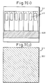
- Step 9 Forming Pad Region Cover Film (Fig. 7(i))
- thermosetting release coating (Fujikura Kasei Co., XB-801) was screen-printed on the pad region (or card edge portion) 503 at a thickness of 100 ⁇ m, and then cured by heating at 150°C for 10 min. to form a cover film 508.
- Step 10 Forming Oxygen Gas-Permeable Membrane (Fig. 7(j))
- An oxygen gas-permeable membrane 507 having a double-layered structure was formed on the glass substrate 511 to entirely cover the substrate upper surface.
- the lower layer of the membrane 507 was first formed by spin-coating a negative-type phtoresist (Tokyo Ohka Kogyo Co., Ltd., OMR-83, viscosity 100 cP), prebaking at 80°C for 30 min., exposing the entire substrate surface to light, and postbaking at 150°C for 30 min.
- the upper layer was then formed by spin-coating a silicone resin (Toray-Dow Corning Silicone Co., SE9176) and curing by heating at 70°C for 30 min. in an oven moistened with the water contained in a Petri dish or a beaker placed in the oven.
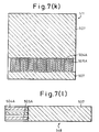
- Step 11 Exposing Pads (Fig. 7(k))
- the cover film 508 formed in the pad region 503 was peeled off with a pincette to selectively remove the oxygen gas-permeable membrane 507 from that portion, and thereby expose the pads (or card edges) 504A and 505A of a miniaturized oxygen electrode.
- the selective removal of the oxygen gas-permeable membrane 507 was effected in such a way that, when the cover film 508 was peeled off, the oxyqen qas-permeable membrane 507 was divided into two parts either side of the site of the cover film 508.
- the oxygen gas-permeable membrane remaining on the glass substrate strongly adhered to the substrate and was not exfoliated by the later treatments, including a water vapor treatment described later.
- the oxygen qas-permeable membrane also ensures a high reliability because that it does not fracture when attached to a catheter and used in medical care, or when used for monitoring the oxygen concentration in a fermenter subjected to sterilization at a temperature of 120°C and a differential pressure of 1.2 atm. for about 15 min.
- Step 12 Separating Miniaturized Oxygen Electrodes (Fig. 7(l))
- a plurality of miniaturized oxygen electrodes were collectively formed on the glass substrate 511 and were cut into chips by a dicing saw.
- the shown example provides seven miniaturized oxygen electrodes from a single substrate.
- the oxygen gas-permeable membrane strongly adhered to the substrate and did not exfoliate during the cutting thereof along a scribe line, and further, did not exhibit a lowered reliability when subjected to a reliability test.
- the miniaturized oxygen electrode according to the present invention can be applied to any clark type device for electrochemically detecting oxygen, including Galvani type, and three-pole type oxygen electrodes.
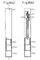
- Figures 8(a), (b) and (c) show an example of the three-pole type miniaturized oxygen electrode, wherein Fig. 8(b) shows an unfinished structure in which an oxygen gas-permeable membrane is not yet formed.
- a working electrode 702, a counter electrode 703 and a reference electrode 704 are formed on a silicon wafer 701 (see Fig. 8(b)) and an oxygen gas-permeable membrane 705 covers the surface except for pads 702A, 703A and 704A of the respective electrodes.
- Figure 8(c) is section of the oxygen sensing site taken along the line I-I of Fig. 8(a), in which an electrolyte composition 715 is filled in grooves formed in the silicon wafer to form a electrolyte-containing material.
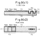
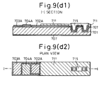
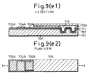
- a three-pole type miniaturized oxygen electrode according to the present invention and having a basic structure as shown in Figs. 8(a) to (c) was produced according to the present invention in the following sequence.
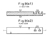
- Step 1 Forming Grooves for Receiving Electrolyte-Containing Material (Fig. 9(a1) and 9(a2))
- grooves 706 for receiving an electrolyte-containing material and an SiO2 insulating layer 707 were formed on both sides of a silicon wafer 701.
- Step 2 Forming Component Electrode Pattern (Figs. 9(b1) and 9(b2))
- Step 3 Forming Photoresist Pattern (Figs. 9(c1) and 9(c2))
- a photoresist pattern 711 was formed to cover the substrate surface except for a region 712 of the oxygen sensing site and a pad region 713.
- Step 4 Screen-Printing Electrolyte Composition (Figs. 9(d1) and 9(d2))
- Step 5 Forming Pad Region Cover Film (not shown)
- Step 6 Forming Oxygen Gas-Permeable Membrane (not shown)
- Step 7 Exposing Pads (Figs. 9(e1) and 9(e2))
- pads 702A, 703A and 704A were exposed.
- Step 8 Separating Miniaturized Oxygen Electrodes (not shown)
- miniaturized oxygen electrodes were produced at a yield of 98% or more and exhibited a good response characteristic, i.e., an output fluctuation of less than ⁇ 3% when measured in water saturated with oxygen.
- the produced miniaturized oxygen electrode is preserved in the dried condition and can be made operative when supplied with water through the oxygen gas-permeable membrane by water vapor sterilization (for example, at 121°C and 2.2 atm.), immersion in water, exposure to a saturated water vapor, etc.
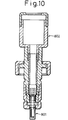
- a miniaturized oxygen electrode 801 of the present invention is conveniently attached to a special adaptor 802 designed for a fermenter (proposed by the present inventors and others in Japanese Patent Application No. 1-231,708).
- the external electrical connection of a miniaturized oxygen electrode is usually carried out by inserting the card edge portion (or pad portion) 503 to a card edge connecter (for example, Fujitsu Ltd., Type 760).
- a card edge connecter for example, Fujitsu Ltd., Type 760.
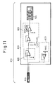
- FIG 11 shows an arrangement of an oxygen concentration measuring device in which a miniaturized oxygen electrode of the present invention is used.
- An oxygen concentration measuring device 810 is composed of a miniaturized oxygen electrode 819 of the present invention and a controller 820.
- the controller 820 is composed of a voltage supply unit 821 for generating a voltage to be supplied to the oxygen electrode 819, a current-to-voltage converter unit 822 for converting an output current from the oxygen electrode 819 to a voltage, a calibration unit 823 for calibrating an output voltage from the converter unit 822 at the oxygen concentrations of 0% and 100%, and a display unit 824.
- the device 810 measures the dissolved oxygen concentration in many kinds of solutions and the oxygen concentration of gas phases.
- the present invention provides a miniaturized oxygen electrode which can be mass-produced at a high efficiency by collectively and uniformly processing a substrate as a whole by using the semiconductor process, a production process thereof, and an electrolyte composition able to be advantageously used therefor.
Landscapes
- Chemical & Material Sciences (AREA)
- Life Sciences & Earth Sciences (AREA)
- Health & Medical Sciences (AREA)
- Biochemistry (AREA)
- General Physics & Mathematics (AREA)
- Electrochemistry (AREA)
- Physics & Mathematics (AREA)
- Analytical Chemistry (AREA)
- Molecular Biology (AREA)
- General Health & Medical Sciences (AREA)
- Chemical Kinetics & Catalysis (AREA)
- Immunology (AREA)
- Pathology (AREA)
- Separation Using Semi-Permeable Membranes (AREA)
- Electrodes For Compound Or Non-Metal Manufacture (AREA)
- Measurement Of The Respiration, Hearing Ability, Form, And Blood Characteristics Of Living Organisms (AREA)
- Measuring Oxygen Concentration In Cells (AREA)
Claims (10)
- Elektrolytzusammensetzung zum Siebdrucken, welche umfaßt:ein organisches Lösungsmittel;ein anorganisches Salz in Form eines feinen Pulvers, das durch ein Siebdrucknetz hindurchgehen kann, und das im organischen Lösungsmittel dispergiert ist; undPolyvinylpyrrolidon, das im organischen Lösungsmittel gelöst ist.
- Zusammensetzung nach Anspruch 1, welche 30 bis 70 % Feststoffe enthält, wobei 50 bis 90 % davon das anorganische Salz sind, und der Rest das organische Lösungsmittel ist.
- Zusammensetzung nach Anspruch 1 oder Anspruch 2, worin das organische Salz Kaliumchlorid oder Natriumchlorid ist.
- Zusammensetzung nach Anspruch 1, 2 oder 3, welche ferner ein Puffermittel umfaßt.
- Zusammensetzung nach Anspruch 4, worin das Puffermittel Phosphat, Acetat, Borat, Citrat, Phthalat, Tetraborat, Glycinsalz oder Tris-(hydroxymethyl)-aminomethansalz ist.
- Zusammensetzung nach einem der vorhergehenden Ansprüche, worin das organische Lösungsmittel ein Alkohol, vorzugsweise Butanol, Pentanol oder Hexanol, ist.
- Miniaturisierte Sauerstoffelektrode, mit:einem elektrisch isolierenden Substrat (303);einem elektrolythaltigen Material (306), das auf einem Teil des Substrats angeordnet ist;zwei oder mehreren Elektrodenkomponenten (304, 305), die auf dem Substrat angeordnet sind, und jeweils ein Ende, das mit dem elektrolythaltigen Material in Kontakt steht, und ein Ende für einen externen elektrischen Anschluß aufweisen; undeiner für Sauerstoffgas durchlässigen Membran (307), die das elektrolythaltige Material bedeckt;wobei das elektrolythaltige Material die Elektrolytzusammensetzung nach einem der vorhergehenden Ansprüche ist, die auf dem Teil des Substrats durch Siebdruck gebildet wird.
- Verfahren zur Herstellung einer miniaturisierten Sauerstoffelektrode, welches umfaßt:Bilden eines elektrolythaltigen Materials auf einem Teil eines elektrisch isolierenden Substrats;Bilden von zwei oder mehreren Elektrodenkomponenten auf dem Substrat, wobei jede Elektrodenkomponente ein Ende, das mit dem elektrolythaltigen Material in Kontakt steht, und ein Ende für einen externen elektrischen Anschluß aufweist; undBilden einer für Sauerstoffgas durchlässigen Membran, die das elektrolythaltige Material bedeckt;wobei das elektrolythaltige Material auf dem Substrat durch das Siebdrucken der Elektrolytzusammensetzung nach einem der Ansprüche 1 bis 6 gebildet wird.
- Verfahren nach Anspruch 8, bei welchem die für Sauerstoffgas durchlässige Membran gebildet wird durch:Bilden eines entfernbaren Deckfilms auf der Zone des Substrats, welche die Enden der Elektrodenkomponenten für einen externen elektrischen Anschluß enthält:Bilden einer für Sauerstoffgas durchlässigen Membran, welche die Substratoberfläche, einschließlich der vom entfernbaren Deckfilm bedeckten Zone, bedeckt; undAbschälen des entfernbaren Deckfilms von der Substratoberfläche, um die für Sauerstoffgas durchlässige Membran von der Zone des Substrats zu entfernen, die vom entfernbaren Deckfilm bedeckt ist, wodurch die Enden der Elektrodenkomponenten für einen externen elektrischen Anschluß freigelegt werden.
- Verfahren nach Anspruch 9, bei welchem der entfernbare Deckfilm durch das Siebdrucken eines duroplastischen Harzes auf der Zone des Substrats, welche die Enden der Elektrodenkomponenten für einen externen elektrischen Anschluß enthält, und Aushärten des Harzes durch Erhitzen gebildet wird.
Priority Applications (1)
| Application Number | Priority Date | Filing Date | Title |
|---|---|---|---|
| EP96109250A EP0743517A1 (de) | 1991-03-20 | 1992-03-19 | Miniaturisierte Sauerstoffelektrode und Verfahren zur Herstellung derselben |
Applications Claiming Priority (4)
| Application Number | Priority Date | Filing Date | Title |
|---|---|---|---|
| JP5722091 | 1991-03-20 | ||
| JP57220/91 | 1991-03-20 | ||
| JP123787/91 | 1991-05-28 | ||
| JP12378791 | 1991-05-28 |
Related Child Applications (1)
| Application Number | Title | Priority Date | Filing Date |
|---|---|---|---|
| EP96109250.9 Division-Into | 1996-06-10 |
Publications (3)
| Publication Number | Publication Date |
|---|---|
| EP0506305A2 EP0506305A2 (de) | 1992-09-30 |
| EP0506305A3 EP0506305A3 (en) | 1993-03-17 |
| EP0506305B1 true EP0506305B1 (de) | 1997-10-22 |
Family
ID=26398237
Family Applications (2)
| Application Number | Title | Priority Date | Filing Date |
|---|---|---|---|
| EP92302399A Expired - Lifetime EP0506305B1 (de) | 1991-03-20 | 1992-03-19 | Siebdruckfähige Elektrolytzusammensetzung, miniaturisierte Sauerstoffelektrode, und Verfahren zur Herstellung derselben |
| EP96109250A Withdrawn EP0743517A1 (de) | 1991-03-20 | 1992-03-19 | Miniaturisierte Sauerstoffelektrode und Verfahren zur Herstellung derselben |
Family Applications After (1)
| Application Number | Title | Priority Date | Filing Date |
|---|---|---|---|
| EP96109250A Withdrawn EP0743517A1 (de) | 1991-03-20 | 1992-03-19 | Miniaturisierte Sauerstoffelektrode und Verfahren zur Herstellung derselben |
Country Status (4)
| Country | Link |
|---|---|
| US (3) | US5281323A (de) |
| EP (2) | EP0506305B1 (de) |
| KR (1) | KR960013687B1 (de) |
| DE (1) | DE69222797T2 (de) |
Families Citing this family (15)
| Publication number | Priority date | Publication date | Assignee | Title |
|---|---|---|---|---|
| GB8927377D0 (en) * | 1989-12-04 | 1990-01-31 | Univ Edinburgh | Improvements in and relating to amperometric assays |
| USD371749S (en) | 1995-07-19 | 1996-07-16 | Ciba Corning Diagnostics Corp. | Solid state planar sensor |
| USD372877S (en) | 1995-07-19 | 1996-08-20 | Ciba Corning Diagnostics Corp. | Solid state planar sensor |
| DE19539518C2 (de) * | 1995-10-24 | 1998-06-04 | Inst Chemo Biosensorik | Verfahren zur Herstellung eines Gassensors |
| DE69720391T2 (de) * | 1996-12-20 | 2004-02-12 | Matsushita Electric Industrial Co., Ltd., Kadoma | Cholesterinsensor und Verfahren zu seiner Herstellung |
| US5945774A (en) * | 1997-03-28 | 1999-08-31 | Industrial Technology Research Institute | Open package for crystal oscillator chips |
| ATE505724T1 (de) * | 2001-09-14 | 2011-04-15 | Arkray Inc | Verfahren, gerät und vorrichtung zur konzentrationsmessung |
| US6872290B2 (en) * | 2001-10-22 | 2005-03-29 | Perkinelmer Instruments Llc | Electrochemical gas sensor with passage for receiving gas |
| US7909981B2 (en) * | 2004-03-03 | 2011-03-22 | Perkinelmer Health Sciences, Inc. | Method and apparatus for improving the performance of an electrochemical sensor |
| GB0414551D0 (en) * | 2004-06-29 | 2004-08-04 | Oxford Biosensors Ltd | Electrochemical sensor |
| US7915058B2 (en) * | 2005-01-28 | 2011-03-29 | Semiconductor Energy Laboratory Co., Ltd. | Substrate having pattern and method for manufacturing the same, and semiconductor device and method for manufacturing the same |
| WO2007072846A1 (ja) * | 2005-12-20 | 2007-06-28 | Hokuriku Electric Industry Co., Ltd. | 半導体センサ及び半導体センサ用センサ本体の製造方法 |
| US11504687B2 (en) | 2016-10-11 | 2022-11-22 | Khalifa University of Science and Technology | Coated chloride salt particles and methods of making and using the same |
| KR102131388B1 (ko) * | 2018-06-21 | 2020-07-08 | 현대자동차주식회사 | 기체센서, 이를 제조하는 방법 및 이를 이용하여 기체를 센싱하는 방법 |
| EP4350338A1 (de) * | 2022-10-06 | 2024-04-10 | Mettler-Toledo GmbH | Sensor und vorrichtung für einen sensor mit gelelektrolyt |
Citations (2)
| Publication number | Priority date | Publication date | Assignee | Title |
|---|---|---|---|---|
| EP0100667A1 (de) * | 1982-07-30 | 1984-02-15 | Biospecific Technologies, Inc. | Feststoffsensor zum Messen von transkutanem Blutgas |
| EP0284518A2 (de) * | 1987-03-27 | 1988-09-28 | Isao Karube | Miniaturisierter Biofühler mit miniaturisierter Sauerstoffelektrode sowie sein Herstellungsverfahren |
Family Cites Families (10)
| Publication number | Priority date | Publication date | Assignee | Title |
|---|---|---|---|---|
| US4001042A (en) * | 1975-09-02 | 1977-01-04 | United Technologies Corporation | Screen printing fuel cell electrolyte matrices using polyethylene oxide as the inking vehicle |
| AU535261B2 (en) * | 1979-11-27 | 1984-03-08 | Asahi Glass Company Limited | Ion exchange membrane cell |
| US4272328A (en) * | 1979-12-05 | 1981-06-09 | Eastman Kodak Company | Buffer overcoat for CO2 ion-selective electrodes |
| US4496451A (en) * | 1981-05-22 | 1985-01-29 | Asahi Glass Company, Ltd. | Ion exchange membrane manufacture for electrolytic cell |
| GB2169608B (en) * | 1984-12-28 | 1988-02-24 | Hoechst Gosei Kk | Process for producting electrically conductive composite polymer article |
| EP0186210B1 (de) * | 1984-12-28 | 1992-04-22 | TERUMO KABUSHIKI KAISHA trading as TERUMO CORPORATION | Ionensensor |
| JPS6239755A (ja) * | 1985-08-16 | 1987-02-20 | Fujitsu Ltd | 小型酸素電極の製造法 |
| US4874500A (en) * | 1987-07-15 | 1989-10-17 | Sri International | Microelectrochemical sensor and sensor array |
| JPH02236154A (ja) * | 1989-03-09 | 1990-09-19 | Fujitsu Ltd | 小型酸素電極の製造法 |
| JPH02240556A (ja) * | 1989-03-14 | 1990-09-25 | Fujitsu Ltd | 酸素電極 |
-
1992
- 1992-03-13 US US07/850,834 patent/US5281323A/en not_active Expired - Lifetime
- 1992-03-19 EP EP92302399A patent/EP0506305B1/de not_active Expired - Lifetime
- 1992-03-19 EP EP96109250A patent/EP0743517A1/de not_active Withdrawn
- 1992-03-19 DE DE69222797T patent/DE69222797T2/de not_active Expired - Lifetime
- 1992-03-20 KR KR1019920004653A patent/KR960013687B1/ko not_active Expired - Fee Related
-
1993
- 1993-11-03 US US08/145,245 patent/US5468408A/en not_active Expired - Lifetime
- 1993-11-03 US US08/145,277 patent/US5478460A/en not_active Expired - Lifetime
Patent Citations (2)
| Publication number | Priority date | Publication date | Assignee | Title |
|---|---|---|---|---|
| EP0100667A1 (de) * | 1982-07-30 | 1984-02-15 | Biospecific Technologies, Inc. | Feststoffsensor zum Messen von transkutanem Blutgas |
| EP0284518A2 (de) * | 1987-03-27 | 1988-09-28 | Isao Karube | Miniaturisierter Biofühler mit miniaturisierter Sauerstoffelektrode sowie sein Herstellungsverfahren |
Non-Patent Citations (1)
| Title |
|---|
| DATABASE WPIL Week 9044, Derwent Publications Ltd., London, GB; AN 90-330569 * |
Also Published As
| Publication number | Publication date |
|---|---|
| KR960013687B1 (ko) | 1996-10-10 |
| US5281323A (en) | 1994-01-25 |
| US5468408A (en) | 1995-11-21 |
| DE69222797T2 (de) | 1998-02-19 |
| US5478460A (en) | 1995-12-26 |
| DE69222797D1 (de) | 1997-11-27 |
| EP0506305A3 (en) | 1993-03-17 |
| EP0743517A1 (de) | 1996-11-20 |
| KR920018479A (ko) | 1992-10-22 |
| EP0506305A2 (de) | 1992-09-30 |
Similar Documents
| Publication | Publication Date | Title |
|---|---|---|
| US5492611A (en) | Miniaturized oxygen electrode | |
| US5281323A (en) | Electrolyte composition for screen printing and miniaturized oxygen electrode and production process thereof | |
| EP0284518B1 (de) | Miniaturisierter Biofühler mit miniaturisierter Sauerstoffelektrode sowie sein Herstellungsverfahren | |
| US6083367A (en) | Oxygen electrode and its manufacture | |
| AU3146795A (en) | Method of measuring gas concentrations and microfabricated sensing device for practicing same | |
| CN113063831B (zh) | 微流控芯片及其制作方法、测试生化需氧量的方法及装置 | |
| JP2650552B2 (ja) | スクリーン印刷用電解質組成物およびそれを用いた小型酸素電極およびその製造方法 | |
| US5326450A (en) | Miniaturized oxygen electrode | |
| KR0124412B1 (ko) | 스크린인쇄용 전해질 조성물 | |
| JP2767868B2 (ja) | 小型酸素電極 | |
| Suzuki et al. | Development of a miniature Clark-type oxygen electrode using semiconductor techniques and its improvement for practical applications | |
| JPS63238548A (ja) | 酸素電極 | |
| JP2530689B2 (ja) | 小型酸素電極 | |
| US5573649A (en) | Miniaturized oxygen electrode and process of producing same | |
| JP2838901B2 (ja) | 小型酸素電極及びその製造方法 | |
| JPH06102230A (ja) | 小型酸素電極 | |
| JP2530690B2 (ja) | 小型酸素電極 | |
| JPH02236154A (ja) | 小型酸素電極の製造法 | |
| Miyahara et al. | Long-life planar oxygen sensor | |
| JP2767614B2 (ja) | 小型酸素電極の製造方法 | |
| JPH05230142A (ja) | ポリビニルピロリドンのpH調節方法およびそれにより調節されたpHを有するポリビニルピロリドンおよびそれを含有するスクリーン印刷用電解質組成物およびこの組成物を用いた酸素電極およびその製造方法 | |
| JPH0843345A (ja) | 小型酸素電極 | |
| JPH09182738A (ja) | 酸素電極およびその製造方法 | |
| JP2844381B2 (ja) | 酸素電極及びその製造方法 | |
| JP2743535B2 (ja) | 集積型センサとその製造方法 |
Legal Events
| Date | Code | Title | Description |
|---|---|---|---|
| PUAI | Public reference made under article 153(3) epc to a published international application that has entered the european phase |
Free format text: ORIGINAL CODE: 0009012 |
|
| AK | Designated contracting states |
Kind code of ref document: A2 Designated state(s): CH DE FR GB LI |
|
| PUAL | Search report despatched |
Free format text: ORIGINAL CODE: 0009013 |
|
| AK | Designated contracting states |
Kind code of ref document: A3 Designated state(s): CH DE FR GB LI |
|
| 17P | Request for examination filed |
Effective date: 19930910 |
|
| 17Q | First examination report despatched |
Effective date: 19951228 |
|
| GRAG | Despatch of communication of intention to grant |
Free format text: ORIGINAL CODE: EPIDOS AGRA |
|
| GRAH | Despatch of communication of intention to grant a patent |
Free format text: ORIGINAL CODE: EPIDOS IGRA |
|
| GRAH | Despatch of communication of intention to grant a patent |
Free format text: ORIGINAL CODE: EPIDOS IGRA |
|
| GRAA | (expected) grant |
Free format text: ORIGINAL CODE: 0009210 |
|
| AK | Designated contracting states |
Kind code of ref document: B1 Designated state(s): CH DE FR GB LI |
|
| DX | Miscellaneous (deleted) | ||
| PG25 | Lapsed in a contracting state [announced via postgrant information from national office to epo] |
Ref country code: LI Free format text: LAPSE BECAUSE OF FAILURE TO SUBMIT A TRANSLATION OF THE DESCRIPTION OR TO PAY THE FEE WITHIN THE PRESCRIBED TIME-LIMIT Effective date: 19971022 Ref country code: CH Free format text: LAPSE BECAUSE OF FAILURE TO SUBMIT A TRANSLATION OF THE DESCRIPTION OR TO PAY THE FEE WITHIN THE PRESCRIBED TIME-LIMIT Effective date: 19971022 |
|
| REG | Reference to a national code |
Ref country code: CH Ref legal event code: EP |
|
| REF | Corresponds to: |
Ref document number: 69222797 Country of ref document: DE Date of ref document: 19971127 |
|
| ET | Fr: translation filed | ||
| REG | Reference to a national code |
Ref country code: CH Ref legal event code: PL |
|
| PLBE | No opposition filed within time limit |
Free format text: ORIGINAL CODE: 0009261 |
|
| STAA | Information on the status of an ep patent application or granted ep patent |
Free format text: STATUS: NO OPPOSITION FILED WITHIN TIME LIMIT |
|
| 26N | No opposition filed | ||
| REG | Reference to a national code |
Ref country code: GB Ref legal event code: IF02 |
|
| PGFP | Annual fee paid to national office [announced via postgrant information from national office to epo] |
Ref country code: FR Payment date: 20100324 Year of fee payment: 19 |
|
| PGFP | Annual fee paid to national office [announced via postgrant information from national office to epo] |
Ref country code: GB Payment date: 20100317 Year of fee payment: 19 |
|
| PGFP | Annual fee paid to national office [announced via postgrant information from national office to epo] |
Ref country code: DE Payment date: 20100422 Year of fee payment: 19 |
|
| GBPC | Gb: european patent ceased through non-payment of renewal fee |
Effective date: 20110319 |
|
| REG | Reference to a national code |
Ref country code: FR Ref legal event code: ST Effective date: 20111130 |
|
| PG25 | Lapsed in a contracting state [announced via postgrant information from national office to epo] |
Ref country code: DE Free format text: LAPSE BECAUSE OF NON-PAYMENT OF DUE FEES Effective date: 20111001 Ref country code: FR Free format text: LAPSE BECAUSE OF NON-PAYMENT OF DUE FEES Effective date: 20110331 |
|
| REG | Reference to a national code |
Ref country code: DE Ref legal event code: R119 Ref document number: 69222797 Country of ref document: DE Effective date: 20111001 |
|
| PG25 | Lapsed in a contracting state [announced via postgrant information from national office to epo] |
Ref country code: GB Free format text: LAPSE BECAUSE OF NON-PAYMENT OF DUE FEES Effective date: 20110319 |