EP0505995B1 - Anzeigevorrichtung für Fahrzeuge - Google Patents
Anzeigevorrichtung für Fahrzeuge Download PDFInfo
- Publication number
- EP0505995B1 EP0505995B1 EP92105074A EP92105074A EP0505995B1 EP 0505995 B1 EP0505995 B1 EP 0505995B1 EP 92105074 A EP92105074 A EP 92105074A EP 92105074 A EP92105074 A EP 92105074A EP 0505995 B1 EP0505995 B1 EP 0505995B1
- Authority
- EP
- European Patent Office
- Prior art keywords
- dial plate
- pointer
- prism
- light
- indicator device
- Prior art date
- Legal status (The legal status is an assumption and is not a legal conclusion. Google has not performed a legal analysis and makes no representation as to the accuracy of the status listed.)
- Expired - Lifetime
Links
Images


Classifications
-
- G—PHYSICS
- G01—MEASURING; TESTING
- G01D—MEASURING NOT SPECIALLY ADAPTED FOR A SPECIFIC VARIABLE; ARRANGEMENTS FOR MEASURING TWO OR MORE VARIABLES NOT COVERED IN A SINGLE OTHER SUBCLASS; TARIFF METERING APPARATUS; MEASURING OR TESTING NOT OTHERWISE PROVIDED FOR
- G01D11/00—Component parts of measuring arrangements not specially adapted for a specific variable
- G01D11/28—Structurally-combined illuminating devices
-
- B—PERFORMING OPERATIONS; TRANSPORTING
- B60—VEHICLES IN GENERAL
- B60Q—ARRANGEMENT OF SIGNALLING OR LIGHTING DEVICES, THE MOUNTING OR SUPPORTING THEREOF OR CIRCUITS THEREFOR, FOR VEHICLES IN GENERAL
- B60Q3/00—Arrangement of lighting devices for vehicle interiors; Lighting devices specially adapted for vehicle interiors
- B60Q3/10—Arrangement of lighting devices for vehicle interiors; Lighting devices specially adapted for vehicle interiors for dashboards
- B60Q3/14—Arrangement of lighting devices for vehicle interiors; Lighting devices specially adapted for vehicle interiors for dashboards lighting through the surface to be illuminated
-
- B—PERFORMING OPERATIONS; TRANSPORTING
- B60—VEHICLES IN GENERAL
- B60K—ARRANGEMENT OR MOUNTING OF PROPULSION UNITS OR OF TRANSMISSIONS IN VEHICLES; ARRANGEMENT OR MOUNTING OF PLURAL DIVERSE PRIME-MOVERS IN VEHICLES; AUXILIARY DRIVES FOR VEHICLES; INSTRUMENTATION OR DASHBOARDS FOR VEHICLES; ARRANGEMENTS IN CONNECTION WITH COOLING, AIR INTAKE, GAS EXHAUST OR FUEL SUPPLY OF PROPULSION UNITS IN VEHICLES
- B60K35/00—Instruments specially adapted for vehicles; Arrangement of instruments in or on vehicles
- B60K35/20—Output arrangements, i.e. from vehicle to user, associated with vehicle functions or specially adapted therefor
- B60K35/21—Output arrangements, i.e. from vehicle to user, associated with vehicle functions or specially adapted therefor using visual output, e.g. blinking lights or matrix displays
-
- B—PERFORMING OPERATIONS; TRANSPORTING
- B60—VEHICLES IN GENERAL
- B60K—ARRANGEMENT OR MOUNTING OF PROPULSION UNITS OR OF TRANSMISSIONS IN VEHICLES; ARRANGEMENT OR MOUNTING OF PLURAL DIVERSE PRIME-MOVERS IN VEHICLES; AUXILIARY DRIVES FOR VEHICLES; INSTRUMENTATION OR DASHBOARDS FOR VEHICLES; ARRANGEMENTS IN CONNECTION WITH COOLING, AIR INTAKE, GAS EXHAUST OR FUEL SUPPLY OF PROPULSION UNITS IN VEHICLES
- B60K35/00—Instruments specially adapted for vehicles; Arrangement of instruments in or on vehicles
- B60K35/50—Instruments characterised by their means of attachment to or integration in the vehicle
-
- B—PERFORMING OPERATIONS; TRANSPORTING
- B60—VEHICLES IN GENERAL
- B60K—ARRANGEMENT OR MOUNTING OF PROPULSION UNITS OR OF TRANSMISSIONS IN VEHICLES; ARRANGEMENT OR MOUNTING OF PLURAL DIVERSE PRIME-MOVERS IN VEHICLES; AUXILIARY DRIVES FOR VEHICLES; INSTRUMENTATION OR DASHBOARDS FOR VEHICLES; ARRANGEMENTS IN CONNECTION WITH COOLING, AIR INTAKE, GAS EXHAUST OR FUEL SUPPLY OF PROPULSION UNITS IN VEHICLES
- B60K35/00—Instruments specially adapted for vehicles; Arrangement of instruments in or on vehicles
- B60K35/60—Instruments characterised by their location or relative disposition in or on vehicles
-
- B—PERFORMING OPERATIONS; TRANSPORTING
- B60—VEHICLES IN GENERAL
- B60Q—ARRANGEMENT OF SIGNALLING OR LIGHTING DEVICES, THE MOUNTING OR SUPPORTING THEREOF OR CIRCUITS THEREFOR, FOR VEHICLES IN GENERAL
- B60Q3/00—Arrangement of lighting devices for vehicle interiors; Lighting devices specially adapted for vehicle interiors
- B60Q3/60—Arrangement of lighting devices for vehicle interiors; Lighting devices specially adapted for vehicle interiors characterised by optical aspects
- B60Q3/62—Arrangement of lighting devices for vehicle interiors; Lighting devices specially adapted for vehicle interiors characterised by optical aspects using light guides
- B60Q3/64—Arrangement of lighting devices for vehicle interiors; Lighting devices specially adapted for vehicle interiors characterised by optical aspects using light guides for a single lighting device
-
- G—PHYSICS
- G02—OPTICS
- G02B—OPTICAL ELEMENTS, SYSTEMS OR APPARATUS
- G02B27/00—Optical systems or apparatus not provided for by any of the groups G02B1/00 - G02B26/00, G02B30/00
- G02B27/01—Head-up displays
- G02B27/0101—Head-up displays characterised by optical features
-
- G—PHYSICS
- G02—OPTICS
- G02B—OPTICAL ELEMENTS, SYSTEMS OR APPARATUS
- G02B27/00—Optical systems or apparatus not provided for by any of the groups G02B1/00 - G02B26/00, G02B30/00
- G02B27/01—Head-up displays
- G02B27/0101—Head-up displays characterised by optical features
- G02B2027/0118—Head-up displays characterised by optical features comprising devices for improving the contrast of the display / brillance control visibility
-
- G—PHYSICS
- G02—OPTICS
- G02B—OPTICAL ELEMENTS, SYSTEMS OR APPARATUS
- G02B27/00—Optical systems or apparatus not provided for by any of the groups G02B1/00 - G02B26/00, G02B30/00
- G02B27/01—Head-up displays
- G02B27/0149—Head-up displays characterised by mechanical features
- G02B2027/0154—Head-up displays characterised by mechanical features with movable elements
-
- Y—GENERAL TAGGING OF NEW TECHNOLOGICAL DEVELOPMENTS; GENERAL TAGGING OF CROSS-SECTIONAL TECHNOLOGIES SPANNING OVER SEVERAL SECTIONS OF THE IPC; TECHNICAL SUBJECTS COVERED BY FORMER USPC CROSS-REFERENCE ART COLLECTIONS [XRACs] AND DIGESTS
- Y10—TECHNICAL SUBJECTS COVERED BY FORMER USPC
- Y10S—TECHNICAL SUBJECTS COVERED BY FORMER USPC CROSS-REFERENCE ART COLLECTIONS [XRACs] AND DIGESTS
- Y10S116/00—Signals and indicators
- Y10S116/36—Illuminated dial and pointer
Definitions
- This invention relates to an indicator device according to the precharacterizing portion of claims 1 and 7.
- a speedometer or the like of the analog meter-type used as a vehicle indicator device does not especially need illumination since it can be visually recognized thanks to the external light; however, in the night or in a tunnel, the device requires illumination since the outside is dark. Therefore, there is a conventional device as shown in Fig. 12 in which characters, a scale, a pointer and etc., are brightened by back light, and also there is a conventional device of the reflection type as shown in Fig. 13.
- a light guide plate 43 is provided between an interior device 41 for driving a pointer 45 and a dial plate 42, and light from light source bulbs 44 is introduced into the light guide plate 43 from its ends 43a as indicated by arrows in the drawings, so that the light guide plate 43 is brightened at the rear side of the dial plate 42, thereby brightening a light-transmitting scale and etc., formed on the dial plate 42.
- the pointer 45 the light is applied from the light guide plate 43 to a boss 45a of the pointer 45 along the outer periphery of a pointer shaft 41a, so that the pointer 45 is brightened by the guidance and diffusion of the light within the pointer 45.
- a light source bulb 54 is provided at the front upper side of a dial plate 52 and a pointer 55, and light is applied to the dial plate 52 and the pointer 55, and is reflected.
- Reference numeral 51 denotes a drive portion for the pointer 55.
- the visibility can be enhanced by increasing the contrast and brightness of the meter; however, in the above conventional vehicle indicator devices, it is difficult to increase the brightness of the bulb to a level higher than the present level because of heat radiation and so on.
- Prior art document CH-A-2 146 644 shows an indicator device, having a rotating pointer mounted on an axis passing through a dial, wherein the pointer and the dial are of translucent materials, the dial being partly covered by a non-translucent plate.
- a first prism means is formed on a lower end of the pointer and a second prism means is formed on a lower section of the dial.
- the prism means are adjacently disposed, such that light from a source situated behind the dial is passing through the dial onto the prism means of the lower section of the dial, where it is emitted to the prism means of the pointer, thereby illuminating the pointer.
- the dial plate constituted by the prism.
- the light incident on the rear side of the dial plate advances to the front face of the dial plate, and goes out from the front face, and at this time the direction of the optical axis of the outgoing light passed only through the dial plate is different from the direction of the optical axis of the outgoing light passed through both of the dial plate and the pointer.
- the light, passed only through the dial plate is influenced by the critical angle of the prism, and can not be directed toward the driver's eye point. Therefore, when viewed from the driver's eye point, the light of the light source provided at the rear side of the dial plate can not be viewed, and the dial plate in a non-brightened condition is visually recognized.
- Those portions of the dial plate having the characters/scale markings are recessed so as not to cause the prism effect, and therefore when viewed from the driver's eye point, the light of the light source provided at the rear side of the dial plate can be viewed through those portions having the characters/scale markings, and as a result those portions having the characters/scale markings are brightened, and can be visually recognized.
- a vehicle indicator device of the present invention includes a dial plate 1 constituted by a prism of a triangular cross-section.
- a light source 2 is provided adjacent to a back face 1b of the dial plate 1.
- a fluorescent lamp (not shown) is mounted within the light source 2, and a light diffusion plate (not shown) for making the brightness of the light source 2 uniform over the entire surface is provided between the fluorescent lamp and the dial plate 1.
- a pointer drive portion 3 is mounted on a bottom surface 1c of the dial plate 1, and an elongate opening 5 is formed in the front surface of the pointer drive portion 3.
- a pointer 4, constituted by a prism, is mounted on the pointer drive portion 3 through the opening 5.
- the pointer 4 is disposed close to a front face 1a of the dial plate 1.
- the two With respect to the positional relation between the dial plate 1 and the pointer 4, the two are disposed adjacent to each other in such a manner that the prism apex angle ⁇ p1 of the dial plate 1 and the prism apex angle ⁇ p2 of the pointer 4 are directed in opposite directions, respectively.
- the front face 1a of the dial plate 1 is inclined toward the eye point at an angle of ⁇ s with respect to a vertical plane.
- the values of the prism apex angle ⁇ p1 and the inclination angle ⁇ s of the dial plate 1 are determined based on the following conditions.
- the values of the prism apex angle ⁇ p1 and the inclination angle ⁇ s of the dial plate 1 are so determined as to achieve this condition, the light of the light source 2 can not be viewed through the dial plate, when viewed from the driver's eye point 7, and only the dark color of the bottom surface 1c of the dial plate 1 can be visually recognized.
- the prism apex angle ⁇ p2 of the prism-type pointer 4 is directed in the direction opposite to the direction of the prism apex angle ⁇ p1 of the dial plate 1. Assuming that light is emitted from the driver's eye point 7, this light passes through the pointer 4, and is incident on the front face 1a of the dial plate 1, and further is incident on the back face 1b of the dial plate 1.
- the value of the apex angle ⁇ p2 is so determined that the angle ⁇ 2 of incidence of the light on the rear side 1b at this time is not more than a critical angle. By doing so, the light of the light source 2 can be viewed through the pointer 4 and the dial plate 1 from the driver's eye point 7, and the pointer 4 brightened against the background of the dark-color dial plate 1 can be visually recognized.
- those portions having the characters/scale markings 6 are recessed as shown in Figs. 3(a) and 3(b), and the front and rear surfaces of each of these portions, that is, she front face 1a and the rear side 1b of the dial plate 1, are parallel to each other. Further, a coating is formed on upper, lower, right and left side walls 6a of this recessed portion.
- an upper portion of a dial plate 1' is formed by a flat plate 8, and those portions of this flat plate on which characters/scale markings 6 are formed are transparent, and a coating which does not allow light to pass therethrough is formed on the remainder. In this case, also, similar effects can be obtained.
- the pointer 4 and the characters/scale markings 6 are brightened against the dark background, and therefore there can be obtained the vehicle indicator device having a high contrast achieving good visibility and recognizability.
- most factors in the reduction of the amount of the light from the light source 2 are based only on the light permeability of the prisms, and therefore the reduction of the light amount is less, so that the indication of high brightness can be obtained, and the lowering of the visual recognition of the indicator device due to a sudden change in the external light can be dealt with.
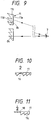
- the above construction can be used as a device for a virtual image indicator device, using a reflection plate 9, as shown in Fig. 5.
- a reflection plate 9 as shown in Fig. 5.
- the position of mounting of a drive portion 3 is different from that shown in Fig. 1, and therefore the manner of mounting of a pointer 4' on the drive portion 3 is different.
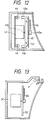
- a pointer 14 is provided close to a front face of a dial plate 11, and a light source 12 is mounted on a rear side of the dial plate 11 through a diffusion plate 15.
- a reflection plate 18 is mounted outwardly of the light source 12.
- a drive portion 13 is connected to a pointer shaft of the pointer 14, and when a signal is inputted to the drive portion 13, the drive portion 13 is operated to angularly move the pointer 14 to a position corresponding to this signal, so that the pointer indicates a corresponding character/scale marking 16.
- the dial plate 11 is made of a transparent member, and as shown in Figs. 7(a) and 7(b), its front face 11a is flat, but prisms 11c of a serrated cross-section are formed on its rear side, and are spaced at predetermined intervals t 1 in a concentric manner about its central portion 11b through which the pointer shaft of the pointer 14 is passed.
- the pointer 14, disposed close to the front face of the dial plate 11, also has prisms 14c of a serrated cross-section spaced at predetermined intervals t 1 over an area extending from the portion thereof (to which the pointer shaft is connected) to its distal end, as in the dial plate 11. As shown in Fig.
- the prism apices at the angle points of angles ⁇ p3 and ⁇ p4 of the opposed prisms 11c and 14c are directed in opposite directions, respectively, and a dark-color coating is formed on a bottom surface 11d of the prism 11c.
- the thickness t 2 of the dial plate 11 as well as the thickness t 3 of the pointer 14 can be reduced.
- the value of the prism apex angle ⁇ p3 of the dial plate 11 is so determined as to achieve this condition, the light of the light source 12 can not be viewed through the dial plate 11, when viewed from the driver's eye point 71, and only the dark color of the bottom surface 11d of the prism 11c of the dial plate 11 can be visually recognized.
- the apex angle ⁇ p4 of the prism 14c formed on the pointer 14 assuming that light is emitted from the driver's eye point 72, this light passes through the prism 14c, and is incident on the front face 11a of the dial plate 11, and further is incident on the prism 11c formed on the rear side of the dial plate 11.
- the value of the apex angle ⁇ p4 is so determined that the angle ⁇ 4 of incidence of the light on the prism 11c at this time is not more than a critical angle.
- the angle ⁇ 5 between the front face 11a of the dial plate 11 and the bottom surface 11d of the prism 11c at the central portion of the driver's eye point 7 is different from that at the end portion of the driver's eye point 73.
- the reason is that by adjusting the inclination of the bottom surface 11d, the permeating light from the light source 12 can be efficiently recognized by the driver, without being intercepted by the bottom surfaces 11d, over the area from the central portion to the end portion of the dial plate 11.
- those portions of the dial plate 11 having the characters/scale markings 16 are recessed in such a manner that the front face 11a and the rear side of the dial plate 11 are parallel to each other, as shown in Fig. 10.
- that portion having the characters/scale markings 16 is formed by a flat plate 18, and the characters 16 and etc., are transparent, and a coating is formed on the remainder.
- the vehicle indicator device of this embodiment also has effects similar to those of the first embodiment, and since the high-brightness indication can be made, this construction can be used as a device for a virtual image indicator device, using a reflection plate, as described above for Fig. 5. Further, if this construction is mounted on a dashboard of the vehicle, it can be suitably used utilizing the external light, even with the light source omitted.
- each of the dial plate and the pointer is constituted by the prism, and the prism apex angles of the opposed portions of the dial plate and the pointer are directed in opposite directions, respectively, and those portions of the dial plate having the characters/scale markings and etc., are recessed, and the light of the light source, passed through both of the dial plate and the pointer can reach the driver's eye point, and the light, passed only through the dial plate, can not reach the driver's eye point, except for those portions thereof having the characters/scale markings and etc.
- the light source can not be viewed through the dial plate from the driver's eye point, except for those portions having the characters/scale markings, and the light source can be viewed through that portion where the pointer and the dial plate overlap each other. Therefore, the characters/scale markings can be visually recognized in a brightened manner against the background of the dark color.
- the reduction of the light amount is less, and the high-brightness indication can be made, and the lowering of the visual recognition due to a sudden change in the external light can be dealt with.
Landscapes
- Engineering & Computer Science (AREA)
- Mechanical Engineering (AREA)
- Chemical & Material Sciences (AREA)
- Combustion & Propulsion (AREA)
- Transportation (AREA)
- Physics & Mathematics (AREA)
- General Physics & Mathematics (AREA)
- Optics & Photonics (AREA)
- Details Of Measuring Devices (AREA)
- Instrument Panels (AREA)
Claims (9)
- Anzeigevorrichtung mit einer Anzeigeplatte (1), einem Zeiger (4), welcher an einer Vorderseite der Anzeigeplatte (1) vorgesehen ist, und einer Lichtquelle (2), wobei jener Zeiger (4) relativ zu der Anzeigeplatte (1) vermittels einer Antriebseinrichtung (3) bewegbar ist, wobei eine Zeigerbeleuchtungseinrichtung mit einer ersten und einer zweiten Prismeneinrichtung vorgesehen ist, und wobei die erste Prismeneinrichtung an dem Zeiger (4) gebildet ist und die zweite Prismeneinrichtung an der Anzeigeplatte (1) ausgebildet ist, wobei die erste Prismeneinrichtung jener zweiten Prismeneinrichtung benachbart angeordnet ist und die Lichtquelle (2) hinter der ersten und der zweiten Prismeneinrichtung derart angeordnet ist, daß deren Licht sowohl die Anzeigeplatte (1) als auch der Zeiger (4) durchläuft und eine Austrittsseite an dem Zeiger (4) erreicht, dadurch gekennzeichnet, daß die Apizes der beiden Prismeneinrichtungen zueinander entgegengesetzt ausgerichtet sind.
- Anzeigevorrichtung nach Anspruch 1, dadurch gekennzeichnet, daß die Anzeigeplatte (1) einen Aussparungsabschnitt aufweist, welcher in solch einer Weise ausgebildet ist, daß das Licht durch diesen Aussparungsabschnitt zu einer Austrittsseite der Anzeigeplatte (1) hindurchtritt.
- Anzeigevorrichtung nach Anspruch 1 oder 2, dadurch gekennzeichnet, daß die Anzeigeplatte (1) mit jener zweiten Prismeneinrichtung derart versehen ist, daß die Anzeigeplatte (1) das einfallende Licht absorbiert.
- Anzeigevorrichtung nach wenigstens einem der Ansprüche 1 bis 3, dadurch gekennzeichnet, daß ein Prisma der zweiten Prismeneinrichtung einen dreieckigen Querschnitt aufweist.
- Anzeigevorrichtung nach wenigstens einem der Ansprüche 1 bis 4, dadurch gekennzeichnet, daß ein Prisma der ersten Prismeneinrichtung einen dreieckigen Querschnitt aufweist.
- Anzeigevorrichtung nach wenigstens einem der Ansprüche 1 bis 5, dadurch gekennzeichnet, daß ein dunkler Überzug auf einer der Oberflächen eines Prismas ausgebildet ist.
- Anzeigevorrichtung mit einer Anzeigeplatte (1), einem Zeiger (4), welcher auf einer Vorderseite der Anzeigeplatte (1) vorgesehen ist, und einer Lichtquelle (2), wobei der Zeiger (4) relativ zu der Anzeigeplatte (1) vermittels einer Antriebseinrichtung bewegbar ist, gekennzeichnet durch eine Vielzahl von Prismeneinrichtungen, welche entsprechend auf dem Zeiger (4) und der Anzeigeplatte (1) jeweils paarweise vorgesehen sind derart, daß jedes Prismenpaar ein erstes Prisma auf der Anzeigeplatte (1) und ein zweites Prisma auf dem Zeiger (4) umfaßt, wobei die ersten und zweiten Prismen eines bestimmten Paares der Prismeneinrichtung einander benachbart angeordnet sind, wobei deren Apizes in einander entgegengesetzte Richtungen weisen.
- Anzeigevorrichtung nach wenigstens einem der Ansprüche 1 bis 7, dadurch gekennzeichnet, daß die erste Prismeneinrichtung des Zeigers (4) Prismen aufweist, welche unter vorbestimmten Abständen derart angeordnet sind, daß diese einen gezackten Querschnitt definieren.
- Anzeigevorrichtung nach wenigstens einem der Ansprüche 1 bis 8, dadurch gekennzeichnet, daß die Lichtquelle auf der Rückseite der Anzeigeplatte (1) vorgesehen ist.
Applications Claiming Priority (2)
| Application Number | Priority Date | Filing Date | Title |
|---|---|---|---|
| JP3064653A JP2848499B2 (ja) | 1991-03-28 | 1991-03-28 | 車両用表示装置 |
| JP64653/91 | 1991-03-28 |
Publications (2)
| Publication Number | Publication Date |
|---|---|
| EP0505995A1 EP0505995A1 (de) | 1992-09-30 |
| EP0505995B1 true EP0505995B1 (de) | 1996-08-21 |
Family
ID=13264407
Family Applications (1)
| Application Number | Title | Priority Date | Filing Date |
|---|---|---|---|
| EP92105074A Expired - Lifetime EP0505995B1 (de) | 1991-03-28 | 1992-03-24 | Anzeigevorrichtung für Fahrzeuge |
Country Status (4)
| Country | Link |
|---|---|
| US (1) | US5261349A (de) |
| EP (1) | EP0505995B1 (de) |
| JP (1) | JP2848499B2 (de) |
| DE (1) | DE69212869T2 (de) |
Families Citing this family (12)
| Publication number | Priority date | Publication date | Assignee | Title |
|---|---|---|---|---|
| US5795113A (en) * | 1996-08-07 | 1998-08-18 | Black & Decker Inc. | Optical unit for image projection and tool incorporating same |
| JP2004184767A (ja) * | 2002-12-04 | 2004-07-02 | Honda Motor Co Ltd | 車両用表示装置およびその導光板 |
| DE10325793A1 (de) * | 2003-06-05 | 2004-12-30 | Borg Instruments Ag | Linearzeiger |
| JP4645407B2 (ja) * | 2005-06-21 | 2011-03-09 | 株式会社デンソー | 計器用表示板とその製造方法およびそれを備えた指針計器 |
| US20090295681A1 (en) * | 2008-05-27 | 2009-12-03 | Gm Global Technology Operations, Inc. | Virtual Image System for Windshields |
| US7961455B2 (en) * | 2009-06-05 | 2011-06-14 | Toyota Motor Engineering & Manufacturing North America, Inc. | Display device having guides linking buttons to display information |
| US9008874B2 (en) | 2011-01-26 | 2015-04-14 | Toyota Motor Engineering & Manufacturing North America, Inc. | System and method for managing power in a vehicle |
| US10099560B2 (en) | 2011-01-26 | 2018-10-16 | Toyota Motor Engineering & Manufacturing North America, Inc. | System and method for maintaining the speed of a vehicle |
| DE102013019565B4 (de) * | 2013-11-22 | 2019-07-04 | Audi Ag | Kombiinstrument |
| DE112014005403B4 (de) * | 2013-11-26 | 2023-02-02 | Yazaki Corporation | Skalenscheibe mit radialen Linien und Kraftfahrzeug-Anzeigegerät mit Skalenscheibe mit radialen Linien |
| DE102014004180B4 (de) * | 2014-03-22 | 2015-11-19 | Audi Ag | Anzeigevorrichtung für ein Kraftfahrzeug |
| JP5913714B1 (ja) * | 2015-10-19 | 2016-04-27 | 矢崎総業株式会社 | 車両表示装置用金属調装飾部品、及び、車両表示装置 |
Family Cites Families (17)
| Publication number | Priority date | Publication date | Assignee | Title |
|---|---|---|---|---|
| CH214644A (de) * | 1939-07-24 | 1941-05-15 | Licentia Gmbh | Messinstrument mit Skalen- und Zeigerbeleuchtungseinrichtung. |
| FR889069A (fr) * | 1941-04-10 | 1943-12-30 | Askania Werke Ag | Dispositif d'éclairement pour instruments de mesure ou d'indication, à index et graduation de cadran apparaissant en clair sur fond sombre |
| US2673288A (en) * | 1948-10-12 | 1954-03-23 | Westinghouse Brake & Signal | Reflector for the production of light beams |
| US2671163A (en) * | 1949-07-01 | 1954-03-02 | Measurements Corp | Illuminated dial scale |
| DE827715C (de) * | 1950-05-05 | 1952-01-14 | Eberhard Adam Dipl Ing | Beleuchtungseinrichtung fuer Messgeraete |
| US2761056A (en) * | 1953-02-13 | 1956-08-28 | Lazo John | Instrument illuminating means |
| US3246133A (en) * | 1964-01-20 | 1966-04-12 | Robert H Hensleigh | Illuminating system |
| US3349234A (en) * | 1965-06-01 | 1967-10-24 | Honeywell Inc | Illuminating apparatus |
| US3561145A (en) * | 1968-03-05 | 1971-02-09 | United States Radium Corp | Light distributing lens system |
| US3853088A (en) * | 1972-06-14 | 1974-12-10 | Bendix Corp | Arrangement for supporting a symbol in an illuminated instrument |
| US4004546A (en) * | 1975-05-02 | 1977-01-25 | Ametek, Inc. | Illuminated indicator gauge |
| JPS553704U (de) * | 1978-06-21 | 1980-01-11 | ||
| JP2823156B2 (ja) * | 1985-07-23 | 1998-11-11 | キヤノン株式会社 | ディスプレイ装置 |
| JPH0713572B2 (ja) * | 1987-01-23 | 1995-02-15 | 日産自動車株式会社 | メ−タ |
| US4874224A (en) * | 1988-05-24 | 1989-10-17 | United Technologies Automotive, Inc. | Vehicular display view control system |
| US4986631A (en) * | 1989-07-17 | 1991-01-22 | Yazaki Corporation | Automotive display system |
| JP3129989U (ja) | 2006-12-26 | 2007-03-08 | 株式会社伸和 | 組立式整理ケース |
-
1991
- 1991-03-28 JP JP3064653A patent/JP2848499B2/ja not_active Expired - Fee Related
-
1992
- 1992-03-05 US US07/846,080 patent/US5261349A/en not_active Expired - Lifetime
- 1992-03-24 EP EP92105074A patent/EP0505995B1/de not_active Expired - Lifetime
- 1992-03-24 DE DE69212869T patent/DE69212869T2/de not_active Expired - Lifetime
Also Published As
| Publication number | Publication date |
|---|---|
| EP0505995A1 (de) | 1992-09-30 |
| DE69212869D1 (de) | 1996-09-26 |
| US5261349A (en) | 1993-11-16 |
| JP2848499B2 (ja) | 1999-01-20 |
| JPH04300736A (ja) | 1992-10-23 |
| DE69212869T2 (de) | 1997-01-23 |
Similar Documents
| Publication | Publication Date | Title |
|---|---|---|
| EP0505995B1 (de) | Anzeigevorrichtung für Fahrzeuge | |
| US4310871A (en) | Illuminating device for instrument | |
| US4892387A (en) | Light controlling sheet | |
| US4872415A (en) | Meter for a vehicle | |
| US5044304A (en) | Illuminated indicator gauge | |
| US7152987B2 (en) | Instrument for vehicle | |
| US20050162843A1 (en) | Tip to tail to center pointer | |
| JP2004233466A (ja) | 車両用表示装置 | |
| JP3568575B2 (ja) | 表示装置 | |
| JP2004340915A (ja) | 車両用計器 | |
| KR20050028300A (ko) | 차량용 표시장치 | |
| US3792248A (en) | Means for controlling illumination of control or service elements on motor vehicle | |
| JPS6210784Y2 (de) | ||
| JP3613426B2 (ja) | 車両用計器装置の指針構造 | |
| JP2007121038A (ja) | 計器用文字盤 | |
| JPH0318987Y2 (de) | ||
| KR100601592B1 (ko) | 차량용 표시장치 | |
| JPS5850260Y2 (ja) | メ−タにおける指針照明装置 | |
| JP2566223Y2 (ja) | 発光指針 | |
| KR20000019150A (ko) | 자동차 계기판의 문자판 조명구조 | |
| JP4655876B2 (ja) | 車両用指針計器 | |
| JP3109715B2 (ja) | 計器指針 | |
| JPH052822Y2 (de) | ||
| JPH0334786Y2 (de) | ||
| JPS6128225Y2 (de) |
Legal Events
| Date | Code | Title | Description |
|---|---|---|---|
| PUAI | Public reference made under article 153(3) epc to a published international application that has entered the european phase |
Free format text: ORIGINAL CODE: 0009012 |
|
| AK | Designated contracting states |
Kind code of ref document: A1 Designated state(s): DE FR GB |
|
| 17P | Request for examination filed |
Effective date: 19930208 |
|
| 17Q | First examination report despatched |
Effective date: 19940524 |
|
| GRAH | Despatch of communication of intention to grant a patent |
Free format text: ORIGINAL CODE: EPIDOS IGRA |
|
| GRAH | Despatch of communication of intention to grant a patent |
Free format text: ORIGINAL CODE: EPIDOS IGRA |
|
| GRAA | (expected) grant |
Free format text: ORIGINAL CODE: 0009210 |
|
| AK | Designated contracting states |
Kind code of ref document: B1 Designated state(s): DE FR GB |
|
| REF | Corresponds to: |
Ref document number: 69212869 Country of ref document: DE Date of ref document: 19960926 |
|
| ET | Fr: translation filed |
Free format text: CORRECTIONS |
|
| PLBE | No opposition filed within time limit |
Free format text: ORIGINAL CODE: 0009261 |
|
| STAA | Information on the status of an ep patent application or granted ep patent |
Free format text: STATUS: NO OPPOSITION FILED WITHIN TIME LIMIT |
|
| 26N | No opposition filed | ||
| REG | Reference to a national code |
Ref country code: GB Ref legal event code: IF02 |
|
| PGFP | Annual fee paid to national office [announced via postgrant information from national office to epo] |
Ref country code: FR Payment date: 20100324 Year of fee payment: 19 |
|
| PGFP | Annual fee paid to national office [announced via postgrant information from national office to epo] |
Ref country code: GB Payment date: 20100322 Year of fee payment: 19 |
|
| PGFP | Annual fee paid to national office [announced via postgrant information from national office to epo] |
Ref country code: DE Payment date: 20110316 Year of fee payment: 20 |
|
| GBPC | Gb: european patent ceased through non-payment of renewal fee |
Effective date: 20110324 |
|
| REG | Reference to a national code |
Ref country code: FR Ref legal event code: ST Effective date: 20111130 |
|
| PG25 | Lapsed in a contracting state [announced via postgrant information from national office to epo] |
Ref country code: FR Free format text: LAPSE BECAUSE OF NON-PAYMENT OF DUE FEES Effective date: 20110331 |
|
| PG25 | Lapsed in a contracting state [announced via postgrant information from national office to epo] |
Ref country code: GB Free format text: LAPSE BECAUSE OF NON-PAYMENT OF DUE FEES Effective date: 20110324 |
|
| REG | Reference to a national code |
Ref country code: DE Ref legal event code: R071 Ref document number: 69212869 Country of ref document: DE |
|
| REG | Reference to a national code |
Ref country code: DE Ref legal event code: R071 Ref document number: 69212869 Country of ref document: DE |
|
| PG25 | Lapsed in a contracting state [announced via postgrant information from national office to epo] |
Ref country code: DE Free format text: LAPSE BECAUSE OF EXPIRATION OF PROTECTION Effective date: 20120326 |